Energy Consumption of Vacuum Freeze Dryer: Comparison
Please note this is a comparison between Version 1 by Yun Guo Guo and Version 2 by Conner Chen.

The vacuum freeze-drying process is characterized by sublimating the frozen object into a solid state in a vacuum environment, sublimating the water from the object, and finally drying it. At the same time, sublimating the water into the cold trap coil to re form ice. This characteristic determines that the freeze-drying machine needs to use the heat medium circulation system to heat the material to sublimate the water of the object, The ice condensed on the cold trap coil also needs a lot of heat to melt and discharge.

During the freeze-drying process of the freeze dryer, the cold trap needs to continuously capture the water vapor generated by sublimation to freeze the cold trap coil. The ice captured by the cold trap coil needs to be melted after each batch of freeze-drying, which in turn requires a large amount of high-temperature defrosting water or thawing steam. For the freeze dryer with heat medium circulation system, sublimation drying also needs to continuously absorb heat, The heat required for the whole process is provided by the electric heater of the heat medium circulation system. The preparation of defrosting water or defrosting steam and the electric heater that provides necessary heat for sublimation require a lot of energy consumption. The freeze dryer consumes too much energy, the freeze-drying cost is high and the energy waste is serious.

  • lyophilizer
  • waste heat

1. Utilization Status of Condensation Heat in the Refrigeration System of a Vacuum Freeze-Dryer

The vacuum freeze dryer must heat the frozen material in the sublimation drying stage to sublimate and escape the frozen ice crystals in the material [1][16]. At present, most heating systems adopt electric heating or steam heating. Among them, the electric heating mode is the preferred heating mode of the vacuum freeze-dryer because of its advantages of safety, cleaning, convenient control, and simple equipment. At the same time, the sublimation drying time accounts for more than 80% of the total time in the whole operation process of the lyophilizer [2][17]. Whether it is electric heating or steam heating, the cost is much lower.
While heating the materials in the freeze-drying box, it is necessary to use the refrigeration unit to cool the cold trap of the freeze-drying machine at a low temperature, so as to freeze the water vapor generated in the heating sublimation process, maintain the vacuum in the freeze-drying machine, and maintain the vacuum conditions for the continuous sublimation of ice crystals [3][4][18,19]. While the refrigeration unit cools the cold trap, it also needs to discharge the heat of the refrigeration unit to the outside through the condenser and absorber. Therefore, the waste heat discharged by the refrigeration unit can be considered as the heat source of the freeze-drying box.
The comprehensive utilization of heat discharged from the refrigeration system was put forward and put into practice as early as 20 years ago. However, due to the inconvenient adjustment of exhaust heating at that time, and most of the sublimation time, the exhaust heating of the compressor of the refrigeration system is greater than the heat required for sublimation. At this time, it is difficult to use the exhaust of the compressor to heat, resulting in poor economy of compressor exhaust heating [5][20]. To solve this problem, Lin Yongjin et al. proposed to add an electric three-way valve at the outlet of the compressor and adjust the opening of the electric three-way valve according to the outlet temperature of the refrigerant of the exhaust heater to adjust the amount of exhaust heating, but this method can reduce the efficiency of the compressor. It is easy to lead to the instability of the temperature of the refrigerant, and then a water source heat pump heating mode with cooling water as the low-temperature heat source is proposed [6][21]. However, this method will increase the number and complexity of lyophilizer equipment.

2. The Utility Model Relates to an Energy Saving System for a Lyophilization Machine Using Solar Energy Absorption Refrigeration

This paper presents an energy saving system of the lyophilizer using solar energy absorption refrigeration. This energy saving system has been granted a Chinese patent (national patent number: ZL201810620783.1), and the schematic diagram of the system is shown in Figure 1.
Figure 1. Energy saving system diagram of a lyophilizer using solar energy absorption refrigeration. 1—generator; 2—condenser; 3—evaporator; 4—absorber; 5—refrigerant throttle valve; 6—solution throttle valve; 7—solution pump; 8—solar collector; 9—solar energy heat collecting circulating pump; 10—refrigeration hot water tank; 11—water tank overflow port; 12—defrost storage tank; 13—defrost valve; 14—cold trap of lyophilizer; 15—cold trap coil; 16—cold trap discharge valve; 17—defrost water recovery valve; 18—defrost water recovery pump; 19—air conditioning heat exchanger; 20—air conditioning waste heat recovery pump; 21—waste heat using circulating pump.

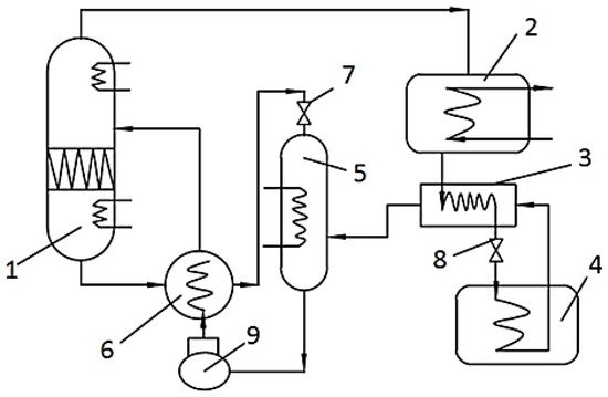
2.1. Composition of the System

The invention relates to an energy saving system of a lyophilizer using solar energy absorption refrigeration. The system consists of a total of three units, which are the solar energy collection unit, absorption refrigeration unit, and heat storage unit. Each unit is composed of its own components, and each unit contains only the components that play a major role in the operation of the system, and the rest of the components are not shown in the system. The specific composition of each unit is as follows: Absorption refrigeration unit is composed of generator 1, condenser 2, evaporator 3, and absorber 4. The solar heat collecting unit comprises a solar collector 8, a refrigeration hot water tank 10 connected with the solar collector, and an electric heater for heating the refrigeration hot water tank. The heat storage unit comprises a defrost storage tank 12 and an air conditioning waste heat recovery mechanism.
In the heat collection system, the solar collector, as the heat source of the system, forms a closed heat collection loop with the heat storage tank and circulating water pump, etc [7][22], and collects heat for the system throughout the year. Therefore, it is particularly important to improve the efficiency of the collector for saving energy consumption. The system adopts the vacuum tube collector, which is usually composed of side-by-side transparent coaxial glass tubes. The vacuum state is formed between the two glass tubes, which eliminates the convection heat loss and reduces the heat conduction loss. The vacuum tube has a large heat capacity, which can obtain heat in a short time. Additionally, the heat pipe has the characteristics of one-way heat transfer, so that hot water will not dissipate downward to the surrounding environment along the heat pipe at night. The vacuum insulation effect is better than that of a flat plate [8][23]. In addition, vacuum tubes have excellent frost resistance and can be widely used in many fields.

2.2. The Connection Mode of Each Component

The connection mode of each component is as follows: generator 1, condenser 2, evaporator 3, and absorber 4 are successively connected through the refrigerant pipeline, and refrigerant throttle valve 5 is arranged on the refrigerant pipeline between condenser 2 and evaporator 3. A solution circulation pipeline is arranged between the generator 1 and the absorber 4, and a solution throttle valve 6 is arranged on the solution circulation pipe between the generator 1 and absorber 4, and a solution pump 7 is arranged on the solution circulation pipe between absorber 4 and generator 1, along the direction of medium flow.
The defrost storage tank 12 is connected with solar collector 8 and the refrigeration hot water tank 10. The solar heat collection circulation circuit is provided with a solar heat collection circulation pump 9. The refrigeration and hot water tank are connected to generators 1 and 10 for heat exchange, defrosting tank 12 by air conditioning waste heat recovery, and the absorption refrigerating unit connected to the condenser and absorbers 2 and 4, used as a condenser, and absorbers 2 and 4, used to recycle waste heat, while air conditioning pumps 20 sets of recovery of waste heat in air conditioning waste heat recycling on the pipeline. The defrost water circulation pipeline is connected between the defrost storage tank 12 and the cold trap 14 of the lyophilizer, and the top of the defrost storage tank 12 is provided with a water tank overflow port 11. The air conditioning waste heat exchanger 19 is arranged inside the defrost storage tank 12, and the two are communicated with each other and are connected with the air conditioning waste heat recovery pump 20. The cold well 14 of the lyophilizer is provided with a cold trap coil 15 and a cold trap discharge valve 16. For the defrost water circulation pipeline in this example, along the direction of medium flow, the defrost water circulation pipeline between the defrost storage tank 12 and the cold trap 14 of the lyophilizer is provided with a waste heat utilization circulation pump 21 and defrost valve 13. Defrost water recovery valve 17 and defrost water recovery pump 18 are arranged on the defrost water circulation pipe between the cold trap 14 of the lyophilizer and the defrost water storage tank 12.
The system adopts ammonia absorption refrigerator, which uses H2O as an absorbent and NH3 as a refrigerant, uses the heat provided by solar energy as compensation and uses the characteristics of solution to cool. The ammonia absorption refrigerator can produce low temperature below 0 °C [9][24], and the refrigerant pair will not crystallize, making it is easier to realize air cooling. Its working principle is as follows: The collector converts the radiant energy of the sun into heat energy to heat the circulating water in the collector, and the circulating hot water is used as the heating heat source of the generator to heat and evaporate the ammonia in the solution into ammonia; ammonia enters the condenser and is cooled into liquid ammonia by the cooling water in the condenser pipe; the refrigerant liquid under the condensation pressure is depressurized through the throttling device and enters the evaporator to absorb heat and evaporate into ammonia for refrigeration; the diluted ammonia solution generated by the heated evaporation of the generator flows back to the absorber through the solution heat exchanger to absorb the ammonia generated by the evaporator, enters the solution heat exchanger through the solution pump, and enters the absorber again to complete the circulation. The system diagram is shown in Figure 2.
Figure 2. Ammonia absorption refrigeration system. 1—distillation tower; 2—condenser; 3—supercooler; 4—evaporator; 5—absorber; 6—solution heat exchanger; 7, 8—throttle valve; 9—ammonia pump.

2.3. System Operation Scheme

The specific operation scheme of the system is as follows:
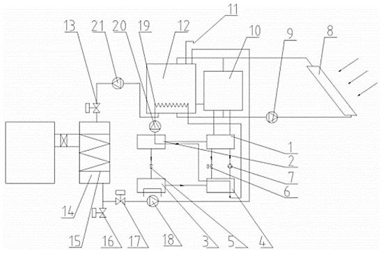
  • When the absorption refrigeration unit is working, the waste heat generated by condenser 2 and absorbent 4 is connected to the waste heat exchanger 19 of the air conditioning in the defrost storage tank 12 through the waste heat recovery pump 20, and the waste heat of the air conditioning is used as the heat source to heat the water in defrost storage tank 12. The hot water prepared in defrost storage tank 12 can promote the heat collection cycle of refrigeration hot water tank 10 and solar collector 8. There are two states according to whether the cold trap 14 of the lyophilizer needs defrosting:
    • If the lyophilizer is not running, the defrosting valve 13 is closed at this time. The heated water in the defrosting water storage tank 12 circulates between the defrosting water storage tank 12 and the solar collector 8 under the action of the solar heat collection circulating pump 9. At the same time, it exchanges heat with the hot water cooled by the generator 1 in the cooling hot water tank 10 to reduce the load of the solar collector 8.
    • When the lyophilizer is in operation, frost will form in the cold trap 14 of the lyophilizer, which needs to be defrosted. At this time, the defrost valve 13 is opened. At this time, the moisture of 12 in the defrost storage tank exits a branch, and under the action of the waste heat circulation pump 21, it enters the cold trap 14 of the lyophilizer through the defrost valve 13, and the high temperature defrost water removes the frosting on the coil 15 of the cold trap. At this point, the defrosting water recovery valve 17 opens, and the melted low-temperature defrosting water enters the defrosting storage tank 12 again under the action of the defrosting water recovery pump and is heated by the waste heat exchanger 19 of the air conditioning with the waste heat of the air conditioning, thus forming a defrosting water cycle. Because defrost storage tank 12 is connected with refrigeration hot water tank 10 and solar energy collector 8 by solar energy heat collection circulation pump 9, defrost water can play a good defrost effect under the heating of double heat sources. When the defrost is finished, defrost valve 13 and defrost water recovery valve 17 are closed. At this point, the water in the defrost storage tank 12 will circulate in the solar heat collection cycle circuit again, and the auxiliary heating cycle will be carried out on the refrigeration hot water tank 10.
  • When the absorption refrigeration unit stops working, the solar heat collection unit heats the defrosted water in the defrost storage tank 12, and the electric heating of the solar heat collection unit itself can also meet the heat required by the defrost storage tank 12. If it is necessary to defrost the cold trap 14 of the lyophilizer, the defrost water circulation pipeline is opened and the defrosted water is used to defrost.
Video Production Service