Your browser does not fully support modern features. Please upgrade for a smoother experience.
Please note this is a comparison between Version 2 by Catherine Yang and Version 1 by Joshuva Arockia Dhanraj.
In the realm of solar power generation, photovoltaic (PV) panels are used to convert solar radiation into energy. They are subjected to the constantly changing state of the environment, resulting in a wide range of defects.
- fault detection
- Photovoltaic Panels
1. Faults Occurring in PV Panels
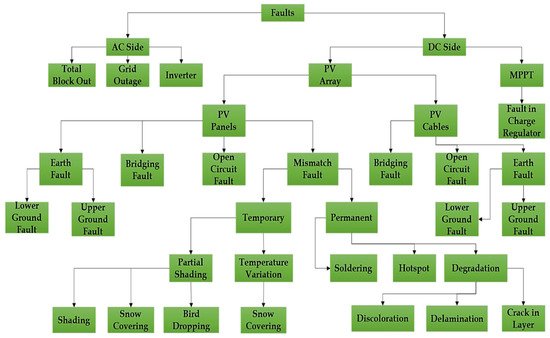
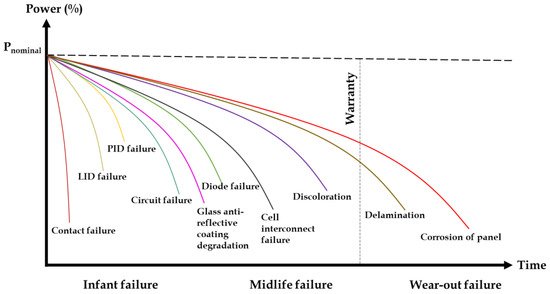
In addition to large-scale solar panels initiatives, a major chunk of studies analyze various faults caused by issues such as installation faults, poor maintenance by the consumer, system overload, hardware issues, connection faults, malfunctions, and other environmental influences such as dust, water droplets, bird droppings, and partial shadowing conditions. Figure 1 shows the classification of faults that occur in PV panel arrays and Figure 2 shows the possible faults that occur in the life cycle of a PV panel. Recent research into PV systems failure has resulted in the development of novel approaches for detecting and locating the different kinds of defects existing. These methods have assisted in the improvement of PV systems dependability and longevity. Figure 1 depicts the classification of several defect discovery procedures used to determine the kind and locality of faults in PV systems on both the DC and AC sides [13][1].

Figure 1.
Classification of faults that occur in PV array panel.

Figure 2. Possible faults that occur in the life cycle of PV panels.
If the defect is found on the PV system’s DC side, a microscopic study can be performed to determine the cause. Analytical approaches have been found to be quite beneficial for microscopic analysis. ATIR, SEM, and X-ray microtomography are some of the most important and latest microanalysis methods documented in the literature [14][2]. The decline in DC power output is the first sign that a PV system is malfunctioning. However, after examining the electrical properties of a PV system, it can be determined that a problem exists. The modules are visually inspected when the defect location has been determined [15][3]. Yellowing, cell fractures, corrosion in connectors links, electrical short circuit defects, bypass diode failure, back-layer polyethylene fractures, bubble formation and matrix cracking in the encapsulate, oxidation and discoloration in intersection wires, encapsulate discoloration, and other defects are visually inspected on the module. If a malfunction occurs on the PV system’s AC side, the system’s power flow will be zero. Concerning Figure 1, from the literature [16][4], the DC side of PV panels are more affected compared to the AC side and thus the major faults of the DC side of PV panels are discussed below such as partial shading fault, short circuit (SC) fault, open circuit (OC) fault, and faults in diode-blocking and bypass diode.
1.1. Partial Shading Fault
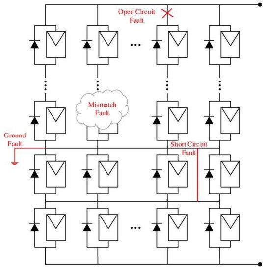
The chief source of power for solar panels is sunlight. Whenever the radiation of the sun is interrupted, the solar panels cannot be utilized efficiently. Most of the solar panels fail to receive sunlight due to passing clouds, snowfall, the panel being covered by water, dirt and bird droppings, and due to tree shadow, which finally results in power loss. Referring to Figure 3, in perilous situations, it is necessary to diagnose and indicate the problem to the operator [13][1].
1.2. Short Circuit (SC) Fault
The solar panel suffers not only when it is exposed to sunlight but also during rain and snowfall; the water droplets might by chance descend into the PV modules. In addition to the above-mentioned situations, aging is a main factor for the short circuit fault, particularly when the solar panel is used for a long period. Figure 3 shows the short circuit fault.
1.3. Open Circuit (OC) Fault
In solar panels, the manufacturer uses many connections between PV modules or solar cells. Due to the aging of low-quality electrical wires and more loads, some disconnection might occur in the circuit. In such situations, the solar power panel fails to produce electrical energy. This kind of fault is called an open circuit fault. An example of an open circuit fault is shown in Figure 3.
1.4. Faults in Diodes—Blocking and Bypass Diodes
The diode used in solar PV panels is used as a feed check valve. Most commonly, two types of diodes are used: one is blocking diode and the other one is bypass diode. Blocking diodes are used to allow the electrical current only in one direction and are connected in series to the solar cell. Bypass diodes are connected in parallel and are used to prevent the backflow of current from strongly exposed cells to a weaker solar cell. Hence, it is highly essential to diagnose faults in solar panel diodes [14][2]. The online/remote supervision approach helps improve the fault detection of a solar system. The faults mentioned above are to be monitored with the help of remote supervision methodology as it helps the consumer with further maintenance activity [15][3].
2. Online/Remote Supervision of PV Panel
Online monitoring systems comprise various sensors such as a temperature sensor, a voltage sensor, and a smart monitoring system with prescribed machine learning techniques adapted for system monitoring. The sensors measure the voltage and the temperature. Moreover, solar radiation is measured using reference solar cells [16][4]. In this type of monitoring system, communication is carried out via existing DC power lines, requiring no extra installation. This technology is called power line communication. The PV systems are arrayed to measure solar irradiance, voltage, and temperature. Santiago Silvestre et al. describe the monitoring of current, voltage, power, cosine, frequency, irradiance, partial shading, and module temperature. The parameters mentioned above are measured using Pt100 sensors and various sensors with calibrated solar cells closer to the geometric center. The invertor’s data acquisition system is used to record the data. Downloading data is handled by software that employs OPC HDA technology, and OPC uses fault detection algorithms for day-to-day review [17][5].
Specific sets of fault test data must be selected under different operating situations to maximize the fault detection in PV power generation. In certain temperature and irradiance conditions, a combination of PIC18F8720 microcontroller and Zigbee wireless sensor has been used to carry out the fault diagnosis [18][6]. One researcher used a wireless sensor for fault diagnosis in solar power panels by placing WSN nodes along with opposite sensors on the group of panels. After sensing a particular parameter, the diagnosing sensor is taken into consideration for continuing the simulation process. Furthermore, the fault diagnosis system must be equipped with telemonitoring panels for the successful implementation of a graphic user interface [19][7]. Another paper analyzed the characteristics of the terminals used in faulty PV strings and arrays. The paper primarily focused on how to decrease the current and voltage sensor by optimizing the sensor location and investigated the connections to analyze both healthy and faulty PV panels with MPPT tracking and solar array configuration [20][8].
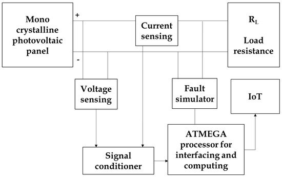
Based on the survey discussed above, it can be concluded that usually most of the people-using sensors can directly communicate through the power line and cables. However, nowadays in large-scale solar power plants, both combined management and security maintenance are essential for the timely detection of problems, ensuring efficiency in the functioning of the equipment. This work proposes a combined usage of an ATMEGA processor and IoT. These are all the techniques used for data processing thanks to which unwanted wiring, accessories, and unwanted expenditures could be controlled in solar panel fault diagnosis. Figure 4 shows the proposed experimental work for fault diagnosis in PV panels +.


Figure 4.
Proposed experimental work for fault diagnosis in PV panel.
Table 1 shows the factors/faults which affect the performance of PV panels in the home grid, small-scale (mini) grid, and large grid farms. These faults are the most prominent problems in PV panels around the world and a monitoring suggestion is provided concerning the grid.
Table 1.
Comparison of methodologies used for predominant defects in PV panel.
| Monitoring Factors | Methodology Used | Methodology Adopted in the Grid System | Monitoring Method |
|---|
| Shading | Multi-objective optimization [21][9] | Home/large grid | Online |
| Hungarian PV system [22][10] | Mini-grid/large grid | Online | |
| Sky illumination model [23][11] | Large grid | Online | |
| Soiling | Quantile regression neural network [24][12] | Home/large grid | Online |
| Machine learning approach [25][13] | Mini-grid/large grid | Online | |
| Infrared thermography [26][14] | Home/large grid | Offline | |
| Dust Accumulation | Deep residual neural network [27][15] | Mini-grid/large grid | Online |
| Acoustic wave method [28][16] | Mini-grid/large grid | Online | |
| Imaging technique [29][17] | Mini-grid/large grid | Offline | |
| Weather | Inverse distance weighting [30][18] | Home/mini-grid/large grid | Online |
| Data analytics [31][19] | Home/mini-grid/large grid | Online | |
| Theta-krill herd algorithm [32][20] | Home/mini-grid/large grid | Online | |
| Delamination | Electric discharge channel [33][21] | Mini-grid/large grid | Online |
| Thermal imaging [34][22] | Mini/large grid | Offline | |
| Aging test [35][23] | Mini/large grid | Offline | |
| Discoloration | I-V characteristic analysis [36][24] | Mini/large grid | Offline |
| Accelerated testing (AT) [37][25] | Mini-grid/large grid | Online | |
| Spectroscopic investigation [38][26] | Mini-grid/large grid | Offline |
References
- Ji, D.; Zhang, C.; Lv, M.; Ma, Y.; Guan, N. Photovoltaic array fault detection by automatic reconfiguration. Energies 2017, 10, 699.
- Duman, S.; Li, J.; Wu, L.; Yorukeren, N. Symbiotic organisms search algorithm-based security-constrained AC–DC OPF regarding uncertainty of wind, PV and PEV systems. Soft Comput. 2021, 25, 9389–9426.
- Ziar, H.; Manganiello, P.; Isabella, O.; Zeman, M. Photovoltatronics: Intelligent PV-based devices for energy and information applications. Energy Environ. Sci. 2021, 14, 106–126.
- He, P.; Li, Z.; Zheng, M.; Wen, F.; Ji, Y.; Wu, X. Damping Characteristics of Interconnected Power Systems with Wind-Photovoltaic-Thermal-Bundled Power Transmitted by AC/DC Systems. J. Energy Eng. 2021, 147, 4021029.
- Doshi, K.; Harish, V.S.K.V. Analysis of a wind-PV battery hybrid renewable energy system for a dc microgrid. Mat. Tod. Proc. 2021, 46, 5451–5457.
- Wasu, A.A.; Kariya, H.M.; Tote, S.S. Evaluating renewable energy using data mining techniques in developing India. Int. J. Sci. Eng. Res. 2013, 4, 232.
- De Keizer, A.C.; Vajen, K.; Jordan, U. Review of long-term fault detection approaches in solar thermal systems. Sol. Energy 2011, 85, 1430–1439.
- Cai, B.; Liu, Y.; Ma, Y.; Huang, L.; Liu, Z. A framework for the reliability evaluation of grid-connected photovoltaic systems in the presence of intermittent faults. Energy 2015, 93, 1308–1320.
- Taveres-Cachat, E.; Goia, F. Exploring the impact of problem formulation in numerical optimization: A case study of the design of PV integrated shading systems. Build. Environ. 2021, 188, 107422.
- Zsiborács, H.; Zentkó, L.; Pintér, G.; Vincze, A.; Baranyai, N.H. Assessing shading losses of photovoltaic power plants based on string data. Energy Rep. 2021, 7, 3400–3409.
- Zhang, K.; Yu, J.; Ren, Y. Research on the size optimization of photovoltaic panels and integrated application with Chinese solar greenhouses. Renew. Energy 2021, 182, 536–551.
- Zhang, W.; Liu, S.; Gandhi, O.; Rodríguez-Gallegos, C.D.; Quan, H.; Srinivasan, D. Deep-Learning-Based Probabilistic Estimation of Solar PV Soiling Loss. IEEE Trans. Sust. Energy 2021, 12, 2436–2444.
- Martin, J.; Jaskie, K.; Tofis, Y.; Spanias, A. PV Array Soiling Detection using Machine Learning. In Proceedings of the 12th International Conference on Information, Intelligence, Systems & Applications (IISA), Creete, Greece, 12–14 July 2021; pp. 1–4.
- Iftikhar, H.; Sarquis, E.; Branco, P.J. Why Can Simple Operation and Maintenance (O&M) Practices in Large-Scale Grid-Connected PV Power Plants Play a Key Role in Improving Its Energy Output? Energies 2021, 14, 3798.
- Fan, S.; Wang, Y.; Cao, S.; Zhao, B.; Sun, T.; Liu, P. A deep residual neural network identification method for uneven dust accumulation on photovoltaic (PV) panels. Energy 2022, 239, 122302.
- Zhao, W.; Lv, Y.; Wei, Z.; Yan, W.; Zhou, Q. Review on dust deposition and cleaning methods for solar PV modules. J. Renew. Sustain. Energy 2021, 13, 032701.
- Chanchangi, Y.N.; Ghosh, A.; Baig, H.; Sundaram, S.; Mallick, T.K. Soiling on PV performance influenced by weather parameters in Northern Nigeria. Renew. Energy 2021, 180, 874–892.
- Acharya, S.K.; Wi, Y.M.; Lee, J. Weather Data Mixing Models for Day-Ahead PV Forecasting in Small-Scale PV Plants. Energies 2021, 14, 2998.
- Farahmand, M.Z.; Nazari, M.E.; Shamlou, S.; Shafie-khah, M. The Simultaneous Impacts of Seasonal Weather and Solar Conditions on PV Panels Electrical Characteristics. Energies 2021, 14, 845.
- Aldosary, A.; Rawa, M.; Ali, Z.M.; Abusorrah, A.; Rezvani, A.; Suzuki, K. Applying a Theta-Krill Herd Algorithm to Energy Management of a Microgrid Considering Renewable Energies and Varying Weather Conditions. J. Energy Res. Technol. 2021, 143, 082108.
- Poulek, V.; Šafránková, J.; Černá, L.; Libra, M.; Beránek, V.; Finsterle, T.; Hrzina, P. PV panel and PV inverter damages caused by combination of edge delamination, water penetration, and high string voltage in moderate climate. IEEE J. Photovolt. 2021, 11, 561–565.
- Dobra, T.; Vollprecht, D.; Pomberger, R. Thermal delamination of end-of-life crystalline silicon photovoltaic modules. Waste Man. Res. 2021.
- Hasan, A.A.; Ahmed Alkahtani, A.; Shahahmadi, S.A.; Alam, N.E.; Islam, M.A.; Amin, N. Delamination-and Electromigration-Related Failures in Solar Panels—A Review. Sustainability 2021, 13, 6882.
- Huot, M.; Kumar, L.; Selvaraj, J.; Hasanuzzaman, M.; Rahim, N.A. Performance Investigation of Tempered Glass-Based Monocrystalline and Polycrystalline Solar Photovoltaic Panels. Int. J. Photoenergy 2021, 2021, 2335805.
- Kim, J.; Rabelo, M.; Padi, S.P.; Yousuf, H.; Cho, E.C.; Yi, J. A Review of the Degradation of Photovoltaic Modules for Life Expectancy. Energies 2021, 14, 4278.
- Hara, K.; Chiba, Y. Spectroscopic investigation of long-term outdoor-exposed crystalline silicon photovoltaic modules. J. Photochem. Photobiol. A Chem. 2021, 404, 112891.
More

