Your browser does not fully support modern features. Please upgrade for a smoother experience.
Please note this is a comparison between Version 2 by Bruce Ren and Version 3 by Lindsay Dong.
Due to the strong absorption and attenuation of electromagnetic waves by water, radio communications and global positioning systems are lacking in the deep-sea environment. Therefore, underwater long-distance communications, positioning, detection and other functions depend on acoustic technology. In order to realize the above functions, the acoustic system of the Fendouzhe human occupied vehicle (HOV) is composed of eight kinds of sonars and sensors, which is one of the core systems of manned submersible.
- Fendouzhe HOV
- acoustic system
- acoustic communication
- USBL
- MB-FLS
- integrated navigation system
1. Introduction
The ocean is the second largest space after land in the four strategic spaces for human development (land, sea, air and space). It is also a strategic development base for biological resources, energy and water resources. The sea area with a water depth ranging from 6000 to 11,000 m, called hadal trenches by scientists, is the deepest ocean area on the planet. What hadal trench science studies is the marine ecology, marine geology and marine life in the abyss. It is the latest research frontier of international earth science, especially marine science. As a powerful vehicle for human beings to explore the ocean and safeguard their rights and interests, deep-sea underwater vehicles (DUVs) will play an important and irreplaceable role. At present, DUVs are mainly divided into human-occupied vehicles (HOVs) and unmanned underwater vehicles (UUVs). Carrying scientists, engineering technicians and the related electronic devices and special equipment, a HOV, which is the essential delivery equipment for scientific research and investigations in the deep ocean, can reach various kinds of complicated deep-sea conditions quickly and precisely. Its operation range and good operation ability are better than those of UUVs. Therefore, HOVs are highly valued by developed countries and are known as “the important cornerstone of oceanographic research” [1][2][3][4][5]. The USA is a world leader in underwater vehicle technology and owns the ALVIN Human Occupied Vehicles, the Deep Challenger HOV, the Nereus HROV and a series of well-known submersibles. Japan, Russia, France and other countries also have some occupied and unoccupied submersibles. Chinese submersibles were developed relatively late. In recent years, with the success of the Jiaolong HOV (Figure 1a), a batch of submersibles with globally advanced levels, such as the Haima ROV, 4500 m AUV, the Shenhai Yongshi HOV(Figure 1b) and the Haiyan underwater glider, have sprung up [6]. In 2020, the third-generation Chinese HOV, named Fendouzhe (Figure 1c), was successfully tested in the Mariana Trench and could cover all sea areas.
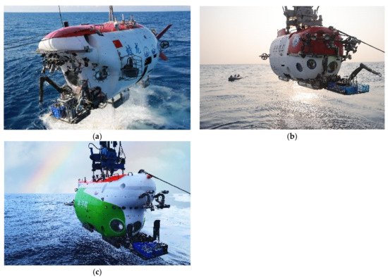
Figure 1. Chinese human occupied vehicles: (a) the Jiaolong HOV, (b) the Shenhai Yongshi HOV and (c) the Fendouzhe HOV.
Since electromagnetic waves are attenuated severely in water, underwater acoustics have now become the most effective transmission medium [7]. In clear sea water, the observation distance of visible light is generally little more than 10 m, and only short-range observations, video and photography can be carried out. Underwater long-distance communications, positioning, detection and other functions depend on acoustic technology. The acoustic system is one of the core systems of a HOV. Compared with unmanned underwater vehicles, human-occupied vehicles experience great risks and technical difficulties when working in the deep sea, which makes the acoustic system of HOV more complex, and it requires higher reliability.
2. Research on the Acoustic System
The Fendouzhe HOV efficiently carries various electronic devices, mechanical equipment and personnel to various deep-sea environments and operation sites quickly and accurately for exploration, scientific investigations and development. According to the operation requirements of the Fendouzhe HOV, its acoustic system is responsible for communications, positioning, obstacle detection, target searching, velocity measurement and other functions. It is composed of eight kinds of sonars and sensors, including underwater acoustic communication (UAC), an underwater acoustic telephone (UAT), an ultra-short baseline (USBL) positioning system, a doppler velocity log (DVL), an obstacle avoidance sonar (OAS), a multi-beam forward-looking imaging sonar (MB-FLS), an altimeter and a strapdown inertial navigation system (SINS). The functions and main technical specifications are shown in Table 1.
Table 1. Functions and main technical specifications of the acoustic system’s equipment.
| Equipment | Function | Main Technical Specifications |
|---|---|---|
| UAC | ||
| ) | ||
Roll/pitch accuracy: ≤0.01°;
Heave accuracy: ≤5 cm
2.1. Underwater Acoustic Communication System
For deep-sea HOVs, deep-sea investigation is a dangerous activity. Ensuring the safety of the scientists in the submersible is the primary problem to be considered in the design. The underwater acoustic communication system is responsible for communication between the HOV and the surface support ship. It is the only communication link between them. Timely communication with the supporting ship can greatly improve the ability of the scientists in the submersible to deal with emergencies. Therefore, the underwater acoustic communication system plays an irreplaceable role in guaranteeing the safety of the personnel.
The underwater acoustic communication system of the Fendouzhe HOV consists of underwater acoustic communication equipment at the end of the HOV and acoustic equipment at the end of supporting ship, as shown in Figure 2.
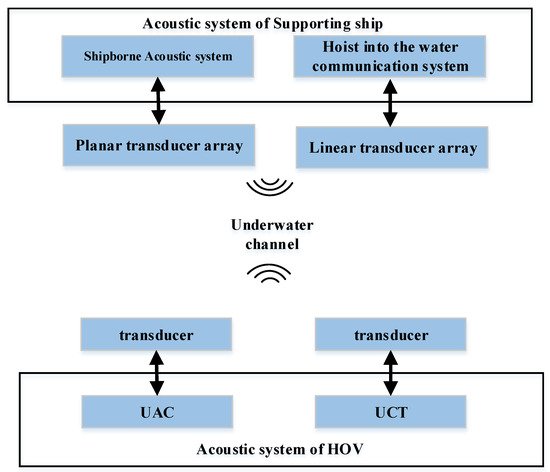
Figure 2. Composition of the underwater acoustic communication system.
2.1.1. Acoustic System of the HOV UAC
The underwater acoustic communication system of the Fendouzhe HOV was developed and perfected on the basis of the successful experience of the Jiaolong/Shenhai Yongshi HOVs. The maximum working water depth is 11 km, and the maximum operating distance is more than 12 km. It has four communication channels, including coherent modulation (MPSK), non-coherent modulation (MFSK), the spread spectrum (FH) and single sideband voice modulation (SSB). Its main function is to provide the HOV with data, text, commands, pictures and voice communication with the surface support ship. The communication system realizes the information exchange and ensures the working safety of the submersible. Through the data driven at the transmitter and the automatic identification technology at the receiver, it can automatically select the appropriate communication mode for a variety of data types without the intervention of the operator, effectively reducing the labor intensity and being more friendly to the operator. Its functional block diagram is shown in Figure 3.
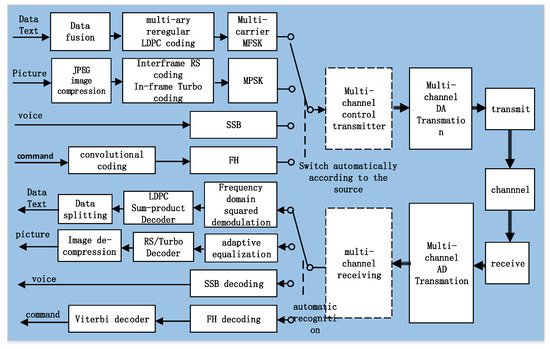
Figure 3. Schematic diagram of the underwater acoustic communication system.
After source coding, various data are organized and encapsulated into packets. After channel coding and MPSK/MFSK modulation, synchronization information is added to the packet to form the transmitted data frame. The transmitting data frame is converted into an analog signal via a DA, which is transmitted to the water the by transmitter.
When the acoustic wave propagates in the underwater acoustic channel, it is not only affected by the noise but also by the multi-path, time-varying and dispersion characteristics of the channel. These factors have a negative impact on the reception.
At the receiving end, the acoustic wave is received by the transducer and converted into a digital signal by an AD. It is then synchronized and demodulated by the digital signal processor (DSP) to extract the information. The different contents of the data packet are separated according to the protocol, the data are displayed or sent to the place where they are needed, the image is decompressed and displayed, and the voice is played as audio.
Based on the Jiaolong/Shenhai Yongshi HOVs, by improving the sound source level and using more advanced communication signal algorithms (see Table 2), the underwater communication system of the Fendouzhe HOV has increased the communication distance to 12 km. The decoding accuracy of the received data packets is guaranteed to be more than 80%.
Table 2. Improvements in the signal processing algorithms.
| Mode | Jiaolong [8] | Shenhai Yongshi [8] | Fendouzhe | Improvement | |||
|---|---|---|---|---|---|---|---|
| Communication (data, pictures, commands, voice) | Working frequency: 7.5–12.5 kHz; | Maximum transmission rate: 10 kbit/s;Maximum working distance: ≥12 km |
|||||
| UAT | |||||||
| MPSK | (1) Turbo +QPSK/8PSK (2) Adaptive equalization + turbo error correction |
||||||
| Voice communication | Working frequency: 8–12 kHz; | Maximum working distance: ≥12 km |
|||||
| USBL | Acoustic positioning | Working frequency: 8–16 kHz; Maximum working distance: ≥12 km; Positioning precision: <5‰R |
|||||
| DVL | Measure velocity, measure flow velocity | Center frequency: 600 kHz; Maximum working distance: ≥50 m; Measured velocity range: ±10 m/s |
|||||
| OAS | Measuring the distance of the HOV in seven directions | Center frequency: 400 kHz; Maximum working distance: ≥100 m |
|||||
| MB-FLS | Acoustic imaging | Center frequency: 225 kHz; Maximum working distance: ≥100 m |
|||||
| Altimeter | Measuring the height from the bottom | Center frequency: 115 kHz; Maximum working distance: ≥200 m |
|||||
| (1) Fountain code + turbo + QPSK/8PSK sparse turbo equalization | (2) Rectify burst error and support length change | (1) Fountain code + turbo + QPSK/8PSK sparse turbo equalization (2) Rectifying burst error and supporting length change |
Improving the error correction performance of the decoder and reducing the number of iterations of the equalizer | ||||
| MFSK | (1) (4,1,7) Convolutional code + Hadamard code + multi-carrier modulation (2) Hadamard decoding +Viterbi hard-decision decoding |
(1) Duality K-code + Hadamard + multi-carrier modulation (2) Hadamard decoding + Viterbi non-binary soft-decision decoding |
(1) Non-binary irregular repeat accumulation (2) Frequency shift keying (12,2) FSK |
Effectively reducing the peak to average power ratio and improving the emission source level and efficiency | |||
| FH | (1) (4,1,7) convolutional code + 2FSK + FH pattern (2) Synchronous detection based on chirp signals |
(4,1,7) Convolutional code + 2FSK + FH pattern | (1) (4,1,9) Convolutional code + 4FSK + FH pattern (2) Synchronous detection based on chirp signals |
(1) The frequency hopping pattern is optimized to suppress the symbol interference caused by channel time expansion(2) The amount of data sent is doubled | |||
| SSB | (1) SSB (2) Dedicated acquisition and playing equipment |
(1) SSB (2) Sources and storage of data are more flexible |
SSB | SINS | Provides HOV attitude, velocity and position information continuously | Heading accuracy: ≤0.02° sec(∅ |
2.1.2. Acoustic System of the HOV UAT
The underwater acoustic telephone can realize voice communications between the HOV and the supporting ship. It adopts the half-duplex working mode and has an emergency communication function in the case of an emergency. Completely independent from the underwater acoustic communication system, it is the backup equipment for the UAC.
The UAT starts up quickly and is easy to operate. Without the cooperation of computer software, it can communicate with the supporting ship only by operating the microphone. On the basis of the Jiaolong/Shenhai Yongshi HOVs, the UAT has been designed through miniaturization, and the transmitting power and conversion efficiency have been improved, so that the communication distance of the underwater acoustic telephone has been increased to 12 km.
2.1.3. Acoustic Communication Equipment of the Supporting Ship: The Hoist-to-Water Communication System
Similar to the Jiaolong/Shenhai Yongshi HOVs, the supporting ship’s acoustic system of the Fendouzhe HOV also adopts the method of hoisting the acoustic linear array (Figure 4) from the supporting ship and lowering it into the water to 200–300 m depth. The following benefits can be obtained: (1) the spatial diversity and combination technology have been realized to overcome the multi-path interference; (2) the receiving array is far away from the supporting ship to reduce the noise interference of the ship, (3) the receiving array is below the seasonal thermocline and has a good sound field. In many sea trials, there was no interaction with the HOV, which proved the safety of the scheme. The acoustic linear array decodes the underwater acoustic signal and transmits the information to the main control computer through the twisted pair in the suspension cable.
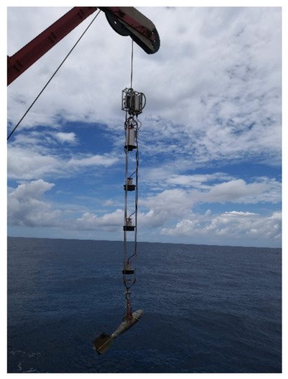
Figure 4. Linear array.
Since the deployment and recovery of an acoustic linear array takes a long time and works under the conditions of less than Class IV sea conditions, and the movement speed of the test supporting ship is required to be less than 2 kn after the linear array has been put into the water, which greatly limits the maneuverability of the supporting ship. These requirements limit the use of acoustic linear arrays.
2.1.4. Acoustic Communication Equipment of the Supporting Ship: The Shipborne Acoustic System
The shipborne acoustic system relies on a tightly integrated transducer array that is mounted on the bottom end of a strong, rigid transducer pole which is installed on the bottom of supporting ship. During operations, the lifting mechanism is lowered and the transducer array extends more than 2 m out from the bottom of the ship. It has the advantages of flexible operation, not being affected by sea conditions and not restricting the mobility of the mothership. It is also a complement to the hoist-to-water communication system, which improves the reliability of the acoustic communication systems of the mothership. However, the installation of a transducer array close to the mothership creates many noise problems and poses a great challenge to communication.
In the acoustic communication system of the Shenhai Yongshi HOV, the scheme of a shipborne acoustic system was first used. An array combining a vertical-cone directional transducer and a horizontal-toroid transducer was installed on the supporting ship, Tansuo-1, as shown in Figure 5. Through measurement, it was found that the noise power in the frequency band of the shipboard acoustic system was 100 times higher than that of the hoist-to-water system. In order to achieve high-speed communications at a low SNR, a series of advanced encoding and receiving algorithms are used. The most representative is the sparse adaptive equalization algorithm based on turbo code, which completes the joint processes of the advanced error correction code and the sparse equalizer [9].
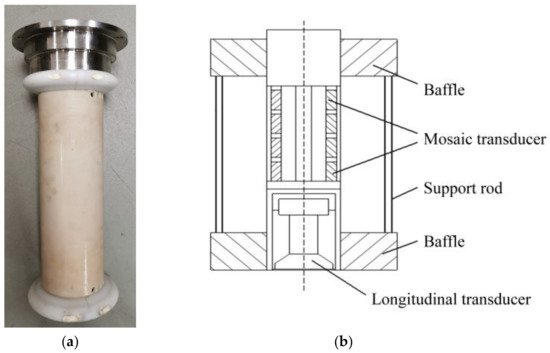
Figure 5. The shipborne transducer array of the Shenhai Yongshi HOV. (a) picture of array, (b) structure picture.
In order to achieve a longer communication distance, the shipborne transducer of the Fendouzhe HOV is designed with a plane array. The transducer array consists of three concentric circles with a total of 19 elements (see Figure 6). It can form a cone beam with a 3 dB opening angle of ±12.3° and obtain a directivity factor of about 17.6 dB. It can effectively improve the sound source level, ensure the communication distance between the supporting ship and the HOV, and significantly reduce the interference of the ship’s noise.
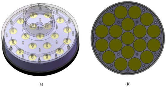
Figure 6. The shipborne transducer array of the Fendouzhe HOV. (a) perspective view, (b) schematic diagram of array element layout.
As the ship moves, turns and swings, and the HOV moves, the relative relationship between the supporting ship and the HOV changes across time, and the shipborne communication system cannot fully grasp the relative relationship. When receiving, 19 beams are generated by the beam-forming technology (Figure 7), which can cover the entire space. During signal processing, the optimal beam is selected for decoding. Even if the relative relationship is always changing during the receiving process, this method can always obtain the optimal signal quality. When transmitting, the opening angle of the beam and the coverage of the main lobe is adjusted adaptively, so that the HOV is always within the range of the main lobe of the communication beam.
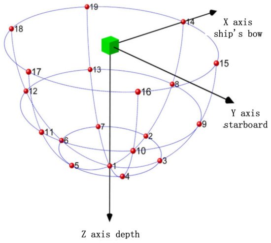
Figure 7. Beam pattern.
2.2. Ultra-Short Baseline Positioning System
There is no global navigation system underwater due to the strong absorption of electromagnetic waves. For the safety of underwater exploration, information on the submarine location is essential. The ultra-short baseline positioning system, with the help of the long-distance propagation characteristics of sound waves in water, has become an indispensable means of positioning for deep-sea operations.
The ultra-short baseline positioning system of the Fendouzhe HOV consists of an ultra-short baseline positioning sonar at the end of the submersible and an ultra-short baseline positioning array at the end of the supporting ship. The ultra-short baseline system obtains the distance and azimuth of the HOV by measuring the phase difference and time difference between the acoustic signals sent by the positioning sonar, so as to get the coordinates of the submersible relative to the array, and then obtains the absolute geodetic coordinates of the submersible through conversion for a compass, GPS and other external auxiliary equipment.
2.2.1. Ultra-Short Baseline Positioning Sonar at the End of the Submersible
The ultra-short baseline positioning sonar at the end of the submersible uses a directional transducer, which is installed above the rear of the HOV. The positioning sonar can work in two modes: synchronous mode and response mode. In synchronous mode, the positioning sonar and the positioning array are triggered by high-precision synchronous pulses. After the synchronization trigger, the positioning sonar transmits the positioning signal; the positioning array starts timing, stops timing after receiving the positioning signal or starts timing again after receiving the next synchronization pulse. The positioning array calculates the distance by measuring the time difference between the trigger time of the synchronous pulse and the received positioning signal of the positioning sonar. According to the maximum submergence depth and sound velocity of the submersible, the positioning signal period of the positioning sonar is 10 s. In response mode, the positioning array sends an inquiry signal to the positioning sonar, and the positioning sonar replies to the inquiry signal after receiving it. The distance is calculated by calculating the time difference between sending the inquiry signal and receiving the reply signal.
The response mode needs to measure the round-trip time from the ship to the submersible to calculate the distance. In the case of large submersible depths, compared with the synchronous mode, the cycle is longer and the data update rate is lower. However, when the synchronization clock is abnormal, the response mode is an important supplement to the synchronization mode to prevent loss of the position information. Under normal circumstances, the ultra-short baseline positioning sonar of the Fendouzhe HOV works in synchronous mode.
2.2.2. Ultra-Short Baseline Positioning Array at the End of the Supporting Ship
The ultra-short baseline positioning array is installed in the shaft of the supporting ship, and the lifting mechanism is lowered during operation. The transducer array extends more than 2 m from the bottom of the ship to avoid the noise interference of the ship as much as possible.
The positioning array has adopted a plane array structure, and the plane array has adopted the regular triangle grid arrangement mode. The advantage of this mode is that when the array element spacing has been determined, the number of array elements used for the same array size will be the least. The array (Figure 8) consists of 31 elements, of which the transmitting element is located in the center; the other 30 elements are receiving elements. The array element distribution diagram is shown in the following figure.
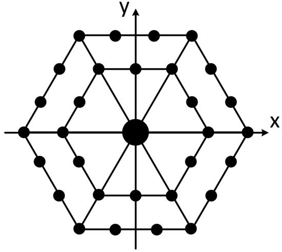
Figure 8. Positioning array element distribution.
In terms of the positioning algorithm, the array receives the positioning signal in the time domain, forms a virtual four-element ultra-short baseline through split beam formation technology, and then measures the target azimuth according to the ultra-short baseline positioning principle. The specific process is shown in Figure 9.
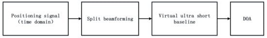
Figure 9. Ultra-short baseline algorithm.
According to the principle of split beam formation, the positioning array is divided into four subarrays (as shown in Figure 10). A “virtual element” is equivalent in the sound center of each subarray, and the four virtual elements form a group of the virtual ultra-short baseline, as shown in Figure 11.
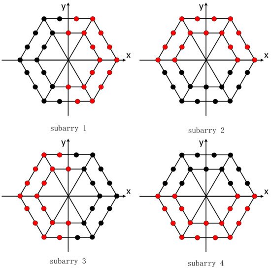
Figure 10. Virtual subarray.
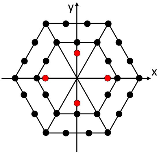
Figure 11. Virtual ultra-short baseline (red is the virtual original).
Through the beam former corresponding to four subarrays, the signal received by the 30 receiving elements outputs four time-domain waveforms as the received signal of the virtual ultra-short baseline, and then uses the basic principle of the traditional four element ultra-short baseline to resolve the signal incident direction, which can effectively suppress noise and improve the signal-to-noise ratio, thus improving the operating range and positioning accuracy of the ultra-short baseline.
2.3. Doppler Velocity Log
The Doppler velocity log (DVL), based on the theory of underwater acoustic doppler effect and vector synthesis, is one of the most widely used and successful pieces of marine navigation equipment. The DVL can simultaneously measure the velocity of the submersible, and the flow and direction of several layers at different depths below. The flow field data and the velocity of the submersible relative to the seabed are necessary parameters for the navigation control and dynamic hovering of the HOV. At the same time, the deep-sea flow field data have important scientific research value.
Compared with hydraulic and electromagnetic logs, the DVL measures the absolute velocity relative to the bottom of the sea, and the measurement accuracy is relatively high. Compared with satellite-based global positioning systems, the DVL does not need external auxiliary equipment to achieve autonomous navigation, which has unique advantages for submersibles and is a key piece of acoustic equipment for submersible.
The transducer array of the DVL adopts a four-beam Janus configuration to form four symmetrically distributed conic beams with a narrow opening angle (Figure 12). The angle between each beam and the horizontal plane is 60°, and the angle between the horizontal projection of two adjacent beams is 90°.
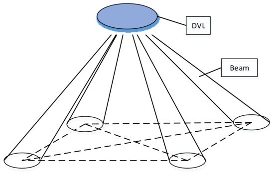
Figure 12. Four-beam Janus configuration diagram.
The DVL is installed under the rear of the submersible, away from the propeller and other noisy positions as much as possible to ensure the accuracy of the velocity and flow measurements. Unlike the DVL of the Jiaolong/Shenhai Yongshi HOVs with a 300 kHz center frequency, the DVL of the Fendouzhe HOV has a 600 kHz center frequency. It has a smaller volume, a lighter weight, greater pressure resistance and stronger performance.
2.4. Obstacle Avoidance Sonar
The obstacle avoidance sonar (OAS) is a kind of ranging sonar. Its working principle is to transmit a pulse signal in a certain direction. When the pulse meets an obstacle, an echo is generated and the time delay between the echo and the transmitting moment is measured to calculate the distance between the collision avoidance sonar and the obstacle.
The Fendouzhe HOV is equipped with seven obstacle avoidance sonars, which measure the distance of obstacles in seven directions: front up, straight in front, front down, straight down, rear down, left and right, so as to avoid obstacles, ensure the safety of the submersible and provide support for the submersible to work in complex areas such as seamounts, ridges, trenches and hydrothermal fields.
2.5. Multi-Beam Forward-Looking Sonar
The multi-beam forward-looking sonar (MB-FLS) is installed on the prow of the HOV, which is different from the single-point ranging of the OAS. It can measure obstacles in an area in front of the submersible and draw a two-dimensional topographic map. It is regarded as the eyes of the submersible and plays an indispensable role in the navigation process.
The Jiaolong/Shenhai Yongshi HOVs use single-beam mechanical scanning forward-looking sonar. However, this kind of sonar only forms a detection beam, and each measurement beam can only aim in one direction, so only the scanning space covered by one beam at a time can be observed in the process of transmitting and receiving. If it is necessary to detect the front area of the submersible, it is necessary to rotate the beam mechanically to make it gradually search and cover the whole area. Higher image resolution means a smaller step angle, which leads to a longer scanning time, so the resolution and data rate are limited.
The Fendouzhe HOV uses a multi-beam forward-looking sonar, which avoids mechanical rotation and can obtain the obstacle situation of the whole area in one measurement cycle. It has the characteristics of fast data update, high resolution and good imaging quality. The multi beam forward-looking imaging sonar has 120 beams, which can cover sectors of more than 90°, and the operating distance is more than 100 m.
2.6. Altimeter
The working principle of an altimeter is similar to that of an OAS. It is also a ranging sonar, which is installed at the bottom of the HOV to measure the distance between the submersible and the seabed. Compared with the OAS, the altimeter has lower frequency, a larger volume and a wider measurement range. In the process of submergence, it can help the diver to predict the time of landing in advance, and make the actions of jettisoning loads, adjusting buoyancy and slowly landing earlier, so as to improve the operational safety of the submersible.
References
- Nanba, N.; Morihana, H.; Nakamura, E. Development of deep submergence research vehicle “SHINKAI 6500”. Tech. Rev. Mitsubish Heavy Ind. Ltd. 1990, 27, 157–168.
- Momma, H. Deep ocean technology at JAMSTEC. Mar. Technol. Soc. J. 2000, 33, 49–64.
- Sagalevitch, A. Experience of the use of manned submersibles in P. P. Shirshov Institute of Oceanology of the Russian Academy of Sciences. In Proceedings of the 1998 International Symposium on Underwater Technology, Tokyo, Japan, 17 April 1998; pp. 403–407.
- Kohnen, W. Manned research submersibles: State of technology 2004/2005. Mar. Technol. Soc. J. 2005, 39, 122–127.
- Liu, F.; Cui, W.; Li, X. China’s first deep manned submersible, JIAOLONG. Sci. China Earth Sci. 2010, 53, 1407–1410.
- Hu, Z.; Wang, L.; Ye, C.; He, Z. Research of acoustic survey devices applied on deepsea vehicles. In Proceedings of the 2016 IEEE/OES China Ocean Acoustics (COA), Harbin, China, 9–11 January 2016; pp. 1–5.
- Yoerger, D.R.; Jakuba, M.; Bradley, A.M. Techniques for deep sea near bottom survey using an autonomous underwater vehicle. Int. J. Robot. Res. 2007, 26, 41–54.
- Wu, Y.; Zhu, M.; Zhang, L.; Li, X.; Yang, B. Underwater acoustic communication system for 4500m manned submersible: Modulation methods and design consideration. Tech. Acoust. 2015, 34, 244–247. (in Chinese).
- Wu, Y.B.; Zhu, M.; Liang, T.; Wang, W.; Yang, B.; Zhang, L.Y.; Li, X.G.; Liu, Y.Y. Shipborne Underwater Acoustic Communication System and Sea Trials with Submersible Shenhai Yongshi. China Ocean. Eng. 2018, 32, 746–754.
More