A thermoelectric effect is a physical phenomenon consisting of the direct conversion of heat into electrical energy (Seebeck effect) or inversely from electrical current into heat (Peltier effect) without moving mechanical parts. In this review, state-of-the-art thermoelectric generators, applications and recent progress are reported.
- thermoelectric generator
- figure of merit
- thermoelectric materials
- nanostructuring
1. Introduction
It is essential for future generations to reduce the quantity of global energy consumed, and this can only be achieved through technological development and use of diversified renewable energy sources i.e. solar, wind, hydropower, in addition to the energy sources currently used. Among these different energy sources, thermoelectricity is currently emerging as a common and promising alternative energy source for the future. Their use is becoming of more interest, as they offer the advantages of recycling waste energy. This means transforming the heat from industry, or road transport into electricity, thus increasing system efficiency and decreasing operating costs and environmental pollution.
Since the discovery of thermoelectricity (TE) in 1821 by Seebeck [1], researchers have been trying to understand and control this phenomenon. Peltier did exactly this in 1834 by discovering the opposite effect [2] and Lord Calvin in 1851 formulated the laws that link these two phenomena [3]. In the following century, in 1909, Edmund Altenkirch [4] correctly calculated, for the first time, the energy efficiency of a thermoelectric generator now known as figure of merit (ZT)
Thermoelectric modules2. Thermoelectric modules
A typical TEG module consists of between ten and a hundred thermoelectric elements of type n and type p, electrically connected in series and thermally in parallel, and interposed between two ceramic layers, as shown in Figure 1. The p-n pairs are joined by conductive tabs connected to the elements via a low melting point solder (PbSn or BiSn). When a temperature gradient occurs between its two junctions, the TEG converts thermal energy into electrical energy according to the principle of the Seebeck effect. This flat bulk architecture is the most widely used and marketed.
The critical challenge in the development of TEGs is the degradation of original properties brought on by thermal fatigue, which is in turn caused by thermal expansion and thermal shock [5]. This degradation can be brutal or progressive and result in a decrease in service life and efficiency. In fact, during normal operation of TE devices, the shunts are periodically heated and cooled and undergo thermal expansion. The TE materials connected to these shunts can experience different effects in expansion from temperature sources, which cause increased stress at the interface between them. These stresses are generally the main cause of mechanism failure and consequently the principal reason why TE materials are not sintered and integrated into shunts [6].
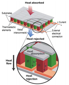
Figure 1. Diagram of a typical thermoelectric device [7]
3. Applications of thermoelectric generatorsTo generate electricity from a TE module, it is necessary to have a temperature difference between its hot and cold surfaces. In other words, it is necessary that the heat recovered from the hot source scatters into the semiconductor elements p and n of the module and then to the cold source which is usually the environment. TEG applications can be classified into three categories depending on the nature of the hot source: (i) radioisotope heat source, (ii) natural heat source, and (iii) waste heat source.
3.1. Radioisotope heat sourcApplications of thermoelectric ge
A radioisotope thermoelectric generator (RTG) is a nuclear electric generator of simple design. It is neither a process of fusion nor nuclear fission, which would require significant constraints on the system, but the natural decay of a radioactive atom, usually plutonium 238 in the form of plutonium dioxide 238PuO2. As they disintegrate, radioactive atoms release heat, some of which is directly converted into electricity [8].
The first RTG was developed by Mound Laboratories in 1954 [9]. The heat source consisted of a 1 cm diameter sphere containing 57 Ci (1.8 Wt) of 210Po inside a nickel-coated steel capsule, all in a Lucite container. With silver soldered chromel-constantan Thermocouples the "thermal battery" produced 1.8 mWe [10]. Three areas, namely the Space domain, power supply devices in remote areas, and the medical domain, have benefited from RTGs, although the last two areas have not flourished because of the risks involved in using radioisotopes.
3.1.1. Space domain
The first RTG launched into space by United States of America was the SNAP 3B in 1961, powered by 96 grams of plutonium metal 238, aboard the Navy Transit 4A spacecraft [11]. In 2010, USA launched 41 RTGs on 26 space systems [12]. Among them were Galileo (launched in 1989 at Jupiter), Ulysses (launched in 1990 as a solar orbital), Cassini (launched in 1997 at Saturn), New Horizons (launched in 2006 to fly over Pluto 2015); and the Curiosity robot from the Mars Science Laboratory (installed on Mars in 2012). Systems for nuclear auxiliary power units (SNAPs) were used for probes that travelled far from the Sun, making solar panels impassable [13].
The RTGs used in the US space program initially included SiGe TE materials installed in the GPHS-RTG, later succeeded by the lead telluride alloys or TAGS used in MMRTG (multi-mission RTG) shown in Figure 2. This MMRTG was developed in the program called enhanced MMRTG or eMMRTG [14] with the use of new skutterudite thermoelectric materials to achieve higher efficiency and low degradation rates that are important for long-term missions to the outer planets [15].
Figure 2. Cutting view of an MMRTG [16]
3.1.2. Power supply devices in remote areas
One of the first terrestrial use of RTGs was made in 1966 by the U.S. Navy for powering environmental instrumentation at Fairway Rock, a small uninhabited island in Alaska. RTGs were used at this site until 1995 [17]. These systems were developed for the power supply of equipment requiring a stable and reliable power source, over several years and without maintenance. Examples of these would be power supplies for systems located in isolated or inaccessible environments like lighthouses and navigation beacons, and weather stations. Similarly, between 1960 and 1980, the Soviet Union built many unmanned lighthouses and navigation beacons equipped with about 1,000 RTGs (Figure 3) [18]. All Russian RTGs have long exhausted their 10-year lifespan and require extreme dismantling measures due to the potentially dangerous source of radioactivity, and the risk of being used in terrorist acts [19]. Obviously, all research and development in this field has been stopped because of the risks already mentioned [20].
Figure 3. RTG used to supply power to lighthouses and navigation beacons [19]
3.1.3. Medical domain
In 1966, small plutonium cells (very small RTGs fed with Pu238) were used in implanted pacemakers to ensure a very long battery life, as shown in Figure 4 [21]. In 2004, about 90 of them were still in use. Many companies have manufactured nuclear-powered pacemakers: ARCO (Perma-grain), Medtronic (Laurens-Alcatel), Gulf General Atomic, Cordis (Telektronic, Accuffix), American Optical, Technologie Biocontrol (Coratomic) and Medical Devices, Inc (MDI) [22]. After the development of lithium batteries, the market for nuclear batteries dried up [23].
Figure 4. Left pacemaker and right RTG battery [21].
3.2. Natuneral heat sourceors
3.2.1. Natural gas and biomass
Pouillet, in 1840, used the Seebeck effect in making a thermoelectric cell with a welded pair of bismuth and copper. The two solderings were immersed in two vessels, one containing melting ice and the other hot water [24]. This apparatus supplying a constant source of dynamic electricity was used by the author to investigate the general laws of currents [25].
At the same time several prototypes of thermoelectric batteries were built and even commercialized, with different sizes and materials for different purposes [26]. For instance, the Oersted and Fourier battery designed for their investigations [27], the Ruhmkorff Thermopile (1860) powered by gas and cooled with water [28], and the gigantic Clamond battery (1879), which was the first thermoelectric battery powered with coal or wood that could have been used in industry, with a height of 2.50 m and 1 m in diameter. Its maximum power was 192 Watts, at 54 Volts and 3.5 Amperes [29]. It is worthy of note that the most remarkable achievement was Melloni's Thermo-Multiplier built in 1830, which was an instrument for making very small amounts of sensitive heat. The battery consisted of about ten Bismuth-antimony pairs that were associated with a Nobili galvanometer. This instrument, was so sensitive that the galvanometer needle deflected by the effect of the natural heat of a person placed 10 m from the battery [30].
Nowadays thermopiles or TEG thermoelectric generators are designed to supply energy to autonomous sensors, installed in remote locations subject to severe environmental conditions i.e. very low temperature, and difficult access, where conventional renewable energy sources, such as solar and wind energy, are not regularly available. Heat is usually supplied by a flameless catalytic burner [31]. A few manufactures of thermoelectric generators powered by natural gas are installed in more than 55 countries. For instance, Gentherm manufactures TEGs with powers ranging from 15 to 550 W. These generators are mainly used on offshore platforms, along pipelines, at altitudes or near gas wells (Figure 5) [32]. Another example is Farwest Corrosion Control, a company that manufactures and installs TEGs for cathodic protection against pipe corrosion and has installed more than 15,000 generators in 51 countries [33].
Figure 5. Gentherm Gas TEG [32]
Several products designed for public use were marketed. One such was the thermoelectric candle radio (1990) which uses the heat from the candles to power the radio via a FeSi2 TE module [34]. These applications have become obsolete with the emergence of other more practical technologies, but despite that, there are still some specific applications, such as the CampStove shown in figure 6. This equipment, designed for camping in general, burns wood to produce 2 W of 0.4 A and 5 V power using a thermoelectric generator in which the connection of the electrical devices is made via a USB port [35].
Figure 6. Picture of a CampStove [35]
3.2.2. Human body
As the heat of the human body is natural and stable, it could be used to supplerate electricity some electricity in very specific applications, such as medical ones [36] [37]. The human body releases around 100 W of heat at rest and 525 W during physical effort [38].
Several investigations have been conducted into wearable therromoelectric generators (WTEGs) since 2001 [39] with the aim of substituting lithium-ion batteries [40] as a power source for portable devices, given that the global market for portable technologies is growing rapidly and is expected to exceed $34 billion by 2020 and $78 billion by 2021 [41]. WTEGs are classified according to their rigid or flexible (extensible or not) [42] architectures in 2D or 3D configurations [43], or in their TE component materials which are inorganic, organic or hybrid [44].
Leonov and Vullers [37] published an ina TE module, iteresting review on WTEGs, focusing on rigid and flexible type thermoelectric generators. They concluded that the wearable thermoelectric generator style was mature and that the major concern was to improve the efficiency of the generator as well as to make it thinner and more flexible. These authors conducted extensive research on rigid substrate TEGs. They developed different WTEG products that used body heat, such as the wireless electrocardiography system integrated into an office shirt. This product was powered by 17 small TE modules integrated into the front side of a shirt as shown in figure 7. They converted the body's natural heat flow into electrical energy of 0.8 to 3 mW depending on the physical activity of the person [45].
Figuris necessary to have a temperature differe 7. WTEG integrated into a shirt [45]
One of the leading companies in this field is IMEC (Belgium), which has been working on thermoelectric generation by people since the 2000s, with a view to power electronic health care systems. IMEC and the Holst Centre have developed several wireless sensors such as the Body-powered EEG Acquisition System that produces 2-2.5mW of power and is worn as a headband. shown in Figure 8(a) [46], and a wireless pulse oximeter (2006) powered entirely by a TEG style watch using commercial Bi2Te3 thermopiles, shown in Figure 8(b), an between its hot and in which the generator develops around 89µW of power [47].
Figure 8. (a) TEG old supplies power to an EEG system mounted on an expandable headband [46]; (b) Wireless pulse oximeter [47]
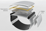
The first thermoelectric wristwatch powered by converting body heat into electrical power was marketed by Seiko and Citizen and dates back to 1999 [48] [49]. The Seiko watch (Figure 9(a)) produced 22 µW of electrical power and an open-circuit voltage of 300 mV with efficiency about 0.1% [50]. Another example is the Dyson TE bracelet (2012) shown in Figure 9 (b), which, using body heat, charged a battery integrated into it to charge a mobile phone or any other mobile device.
Figure 9. (a) Seiko Thermic, wrices. In other wordstwatch [50]; (b) Dyson bracelet [51]
Because of the drawbacks of rigid modules, i.e. high thermal resistance between skin and TEG, flexible modules are more suitable for power generation from body heat, as they can be adapted to the shape of the body, thus increasing the useful surface area for heat capture and reducing thermal contact resistance [52]. Francioso et al. [36] developed a flexible and wearable micro thermoelectric generator composed of 100 array thin film thermocouples of Sb2Te3 is necessary thand Bi2Te3, designed to power very low consumption electronics ambient assisted living (AAL) applications. The best result obtained was 430 mV in open circuit, and an electrical output power up to 32 nW at 40 °C. KIM et al. [53] manufactured a flexible fabric-shaped TEG with 3D printing technology composed of 20 thermocouples and a thickness of 0.5 mm as shown in Figure 10(a). The TEG, when applied to a human body, generated an electrical power of 25 mV at an ambient temperature of 5 °C. A new approach was presented by Suarez et al. [54] using standard bulk legs interconnected to a stretchable low-resistivity eutectic alloy of gallium and indium (EGaIn), all in a flexible elastomer package as shown in figure 10(b). The authors reported a figure of merit (ZT) of 0.35, which they claimed to be better than that of any other similar device reported in the open literature. Zadan et al. [55] introduced a soft and stretchable thermoelectric generator (TEG) with the ability to expand, to explore the integration of this TEGs into wearable technologies. All investigations conducted so far have suggested that this option can only be viable at moderate temperatures, i.e. indoors in particular, and this limits its application together with the high cost of TE modules [56].
Figure 10. (a) Flexible TEG fabrithe heat recovered from the hot source scatters into the semiconducated using dispenser printing technology [57]; (b). Flexible device and test configuration: (A) flexible device tested, (B) circuit voltage open at room temperature [54]
Soleimaor elemeni et al. [58] have published a review on recent developments in inorganic, organic, and hybrid wearable TEGs. The authors concluded that inorganic TE materials remain favorable due to their high ZT (~1), but unfavorable due to their rarity, toxicity and impractical rigidity. Organic TE materials have high flexibility and non-toxic elements, but their weaknesses are low stability in air and complexity in the synthesis process. They reported that hybrid TE materials are the solution to the rigidity of inorganic TE materials and the low efficiency of organic TE materials. These hybrid TE materials are suitable for portable TEGs. Jiang et al. [59] presented a review focused on recent developments of TE materials concerning film- and fiber-based materials for flexible wearable applications. They concluded that these applications will eventually become a reality with the development of preparation technology for film or fiber legs, human thermoregulatory models for designing wearable devices, and integration with other wearable renewable energy conversion devices.
3.2.3. Sun source
A solar thermoelectric generator (STEG) is a system designed to recover heat from solar radiation and convert it into electricity s p and n of the module and then to the cold sousing a thermoelectric generator (TEG). It is becoming a technological alternative and competing with the dominant solar photovoltaic systems despite its low conversion efficiency compared to PV technology [60]. STEGs are classified according to the type of optical sensors used, namely an optical concentration system or not. Optical concentration sensors are usually cylindrical lenses, Fresnel lenses, parabolic mirrors, flat mirrors or parabolic concentrators. Non-concentrated solutions are rather limited to flat plate collectors evacuated or not evacuated, and vacuum tubes [61]. Karthick et al. [62], in a recent review, reported that the use of optical concentrators combined with heat pipe tubes improves the efficiency of solar thermoelectric generators (STEG)ce which is usually the environment.
The first investigation into thermoelectric solar energy dates back to the end of the 19th century, with Weston's patent in 1888 [63][64] which combined a thermopile (TEG) with a mirror or lens to focus solar radiation on hot junctions and a storage battery. The first experimental data on a STEG device were published by Coblentz in 1922 [65] with an efficiency of less than 0.01%. More progress was reported in 1954 on a STEG device by Telkes [66] who demonstrated an efficiency of 0.63% and 3.35% at 1 × and 50 × sun respectively of the optical concentrators in a flat-plate solar energy collector. ZnSb-type alloys in combination with a negative Bi-alloy were used. The most significant investigations on solar thermoelectric generators (STEGs) are summarized in the following. He et al. [67] carried out a theoretical and experimental study on the integration of thermoelectric modules in solar vacuum tube heaters (SHP-TE) as illustrated in Figure 11. Their experimental data showed an electrical efficiency of 1%, which is slightly lower than a system with an organic Rankine cycle but according to the authors the SHP-TE system is simple and has no moving components and its units are easy to replace. On the same principle another creative investigation was done with the use of a parabolic solar concentrator [68][69].
Figure 11. Schematic diagram applications can be classified into three categories depending on the nature of an integrated SHP-TE system [67]
Kraemer et al. [70] used nanostructured thermoelectric materials to develop the solar flat panel thermoelectric generators shown in Figure 12. These TEs achieved a maximum efficiency of 4.6% under an irradiation of 1 kW.m -2. The efficiency was 7 to 8 times higher than the best value previously reported for a flat panel display.
Amatya and Ram [71] combined a commercial Bi2Te3 module with a parabolic concentrator (solar concentration of 66 x suns). A system efficiency of 3% was measured and an output power of 1.8 W was achieved. Rehman et al. [72] proposed a novel collector design for a solar concentrated thermoelectric generator. The system had an electrical efficiency of 1.45% and a maximum optical efficiency of 93.61%. Li et al. [73] evaluated a prototype consisting of a solar concentration thermoelectric generator (CTG) with Fresnel lens (Figure 13). Their results showed that the highest possible CTG efficiency could reach 9.8%, 13.5% and 14.1%, respectively, for Bi2Te3, skutterudite and LAST (silver antimony lead telluride) alloys.
Figure 12. Illustration of a STEG cell consisting of a pair of thermoelectric elements type p and n [70]
Figure 13. Concentrating Solar Thermoelectric Generatorshot source: (a) An experimental prototype of the Concentrating Solar Thermoelectric Generator System; (b) Details of the CTG unit [74]
Photovoltaic and) thermoelectric systems are the only processes that directly convert solar energy into electrical energy [75]. Some investigations were conducted on hybrid photovoltaic-thermoelectric systems [76] and concentrated photovoltaic (CPV)-thermoelectric systems [77]. Another hybrid system consists of the direct coupling of a solar water heater with a thermoelectric module, in order to improve the overall performance of the system producing heat and electricity simultaneously [78]. However, their combination is complex because of their opposing characteristics, as effective integration of the two systems is essential [79]. Sripadmanabhan Indira et al. [80] investigated different configurations of the hybrid system integrating photovoltaic concentrators (CPV) and thermoelectric generators (TEG) and outlined recommendations for future research. The authors reported that the integrated CPV-TEG based solar thermal systems have higher electrical and thermal performances than those of non-concentrated PV-TEG systems. Li et al. [81] compared a hybrid Photovoltaic-thermoelectric (PV-TE) system employing a micro-channel heat pipe array together with the PV electricity generation. The results showed that the electrical efficiencies of the hybrid PV-TE system were about 14% higher than those of the PV system.
Mizoshiri et al. [82] badioisotope heat source, (ii) natural heat souilt a hybrid module composed of a thin-film thermoelectric module and a photovoltaic module. This hybrid module filtered light through an infrared filter (hot mirror) allowing only the light that contributed to photovoltaic conversion to pass through. At the same time, the reflected light was focused on the warm side of the thermoelectric module using a lens. The total no-load voltage of the hybrid thermo-photovoltaic generator showed an increase of 1.3% when compared with using the photovoltaic module alone. As regards TPV/TE hybrid systems, thermophotovoltaic cells (TPV) are capable of converting infrared radiation into electricity. They consist of a heat source, an emitter, a filter and photovoltaic (PV) cells [83]. Unlike photovoltaic solar panels, TPV cells are illuminated by radiant combustion sources. Given that the radiant power density of these sources can be much higher than that of the sun, the electrical power density of TPV cells is much higher than that of solar cells with an efficiency of 24.5% [84]. As of yet, few studies have been conducted into integrated TPV/TE systems. Qiu and Hayden. [85] reported that the efficiency of an integrated system with TPV GaSb cells and TEG was superior to that of individual TPV and TEce, and (iii) waste heat source. For this reason, the TPV/TE hybrid system is an interesting alternative system and further research is required in the future [86]. However, the major concern with hybrid systems is to achieve optimal hybridization, which means ensuring that the sum of the maximum powers produced separately by each PV and TE equals the power produced by the hybrid system [87].
3.3. Waste heat source
A huge amount of low-grade waste heat is released into the environment without any attempt at heat recovery. Over the last three decades much effort has been made to improve the efficiency of thermoelectric technology in heat recovery applications [88]. This is promoted by the fact that TE technology could be easily adapted to the physical parameters such as temperature, pressure, and heat transfer fluid of a given heat recovery application. Waste heat recovery using thermoelectric technology can be divided into two main groups as follows.
3.3.1. Waste heat recovery from industry and homes
Dai et al. [89] reported that in United States 33% of industrial manufacturing energy is released directly into the atmosphere or into cooling systems as waste heat, and this amount of heat could be used to produce 0.9 TWh to 2.8 TWh of electricity per year if thermoelectric materials with average ZT values ranging from 1 to 2 were available. Hence, there is a need for technical and economic studies to develop feasibility for large-scale applications that, in the medium and long term, would make it a competitive source of clean energy [90]. Zou et al. [91] demonstrated that municipal wastewater can be used to produce electricity using a thermoelectric generator (TEG). Their theoretical study performed for the Christiansburg Wastewater Treatment Plant, estimated energy generation of 1094 to 70,986 kWh per year with a saving of USD 163 to USD 6076. In another investigation that used an air-cooling heat recovery device with 120 mm square pipes, the wastewater recovery efficiency was 1.28% and the amortization period for the equipment extended to 8 years [92].
Araiz et al. [93] carried out a techno-economic study into the thermoelectric recovery of hot gases from a stone wool manufacturing plant. They reported a maximum net power production of 45 kW and a Levelized Cost of Electricity at about 0.15 EUR/kWh, which demonstrated the feasibility of the system. Mirhosseini et al. [94] performed a similar investigation using an arc-shaped absorber designed for thermoelectric heat recovery of waste heat from a rotary cement kiln. The economic evaluation showed that the dominant parameter in the system cost is the heat sink.
It is worth noting that heat recovery depends strongly on the ambient temperature. In hot regions, investigations were mainly focused on the recovery of heat released in air conditioning systems [95]. However, investigations on heat recovery were more diversified in cold regions. Killander and Bass [96] developed and tested a prototype of a thermoelectric generator designed to supply small amounts of electricity using heat from existing wood stoves in homes in the cold and isolated regions of northern Sweden. The cost of connection to the grid in this region ranged from USD 5,000 to USD 120,000 per house. The device provided sufficient energy for electric lighting and watching television during the long winter nights. In the Netherlands, Gasunie Research, an energy network operator, developed in 1999-2000, built and tested 20 autonomous (self-powered) boilers that used the heater flame produced to co-generate enough electricity to operate its electrical components using six HZ-20 thermoelectric modules [97]. They concluded that these thermoelectric generators supplied 60 W of electricity, which was enough to run their electrical components. Other tests were carried out in the United States of America and England [98] on residential scale hydronic central heating units that were modified with the addition of a thermoelectric production stage to demonstrate autonomous operation in a realistic environment. The thermoelectric stage is a set of 18 thermoelectric modules made of bismuth telluride alloy, which generates an electrical power of 109 W sufficient to supply the blower, the gas control and the water pump of the hydronic central heating. According to Sornek et al. [99], the commercial success of such an installation has to be focused on: (i) introduction of necessary modifications to the heating devices, (ii) the development of a dedicated structure of the TEG.
In the case of operating conditions in which ambient temperature is not as important as the arrangement of the system off-grid, Bass and Farley [100] tested three thermoelectric generators designed to provide electrical energy in a natural gas field. These generators converted the waste heat produced by the equipment used in the gas field into a thermal energy source for the generators. Electricity was used for cathodic protection, telemetry power supply and lighting. Also, the US military used thermoelectric technology to reduce the logistics of field feeding by integrating thermoelectric devices into the Assault Kitchen that was used to heat food rations out on the field. These devices had no need for an external electrical generator to power the Assault Kitchen. In addition, they produced an excess of electricity that could be used for lighting, battery charging, radio power, communication equipment, etc. [101].
3.3.2. Radioisotope Waste heat recovery from transport systourcems
3.3.2.1. Automobiles
The road transport in Europe represents about 20% of the total carbon dioxide emissions, 75% of which come from private cars, and similar rates are observed in America and Asia [102]. European regulations aim to achieve a CO2 emissions target of 95 g/km by 2021 and 68 g/km by 2025 for passenger cars and light commercial vehicles [103]. It is worth taking into account that two thirds of a vehicle's combustion energy is lost as waste heat, 40% of which is in the form of hot exhaust gas [104],[105]. If about 6% of exhaust heat could be converted to electrical energy, it would be possible to reduce fuel consumption by about 10% [106].
To this end, the major American, Asian and European automobile companies, in collaboration with research institutes and universities, are trying to develop various types of TEGs to improve the fuel economy of their vehicle models, to preserve and gain an additional share in the future automobile market, which will undoubtedly be more restrictive. Agudelo et al. [107] tested a diesel passenger car in a climatic chamber to determine the potential for energy recovery from exhaust gases. They concluded that the potential fuel savings ranged from 8% to 19% and the silencer showed the highest energy losses, so the installation of a TEG needed to be located prior to it. Moreover, there are mainly three possible locations for the TEG [102], namely: (i) The TEG is placed at the end of the exhaust system; (ii) TEG is located between the catalytic converter and the silencer, the best option; (iii) The TEG is located upstream of the catalytic converter and silent. If the weight of the installed TEG and the additional pressure drops in the exhaust system are not optimized, the vehicle will consume more fuel than it needs to save, and consequently the system becomes totally inefficient [108]. The different thermoelectric generators manufactured for automobiles (ATEG) can be compared depending on the shape, material or suitable heat transfer system.
In the late 1980s, Birkholt [109], in collaboration with Porsche, proposed a thermoelectric generator with a rectangular cross-section, which was able to produce up to 58 W under peak conditions with FeSi2 elements. At the end of the 1990s, Nissan Research Center from Japan [110] developed a TE generator with a rectangular cross-section of 72 modules. Each one of these modules contained 8 pairs of Si-Ge elements to be applied to gasoline powered vehicles. The electrical power supplied by the generator was 35.6 W. Later they tested a thermoelectric generator composed of 16 Bi2Te3 modules operating at low temperature; the electrical power generated by the generator was 193 W [111]. In 1992, Hi-Z Technology started the development of a 1 kW thermoelectric generator for diesel truck engines with funding from the U.S. Department of Energy and the California Energy Commission [112]. Amerigon (now Gentherm) developed thermoelectric generators for passenger vehicles between 2004 and 2011 in 5 phases. The project was sponsored by the US Department of Energy (DOE) and counted on the participation of BMW and Ford in Phase 3 and Faurecia in Phase 5. [113]. Phases 1 and 2 dealt with the tests of a low temperature liquid/liquid TEG that developed 500 W and was built with Bi2Te3 materials implanted in a flat plate TEG design [113] [114]. In phase 3, a two stage flat plate-shaped gas/liquid TEG at a high temperature (above 600 °C) consisting of TE elements segmented in two stages, and based on a half-Heusler alloy (Zr, Hf), was installed near the hot gas inlet and Bi2Te3 elements near the outlet. The measured output power resulted in about 100 W [113] [115]. During phases 4 and 5, a new cylindrical design was selected due to the limitations encountered with the flat plate design, and power output reached over 200 W in phase 4. In the final phase power output improvement was achieved on a BMW X6 (Figure 14), and a Lincoln MKT (Ford) with more than 600 W of power produced in vehicle tests and more than 700 W in bench tests [113] [116][117]. This success conducted Gentherm, BMW and Tenneco in 2011 to launch a new program of seven years using a new thermoelectric cartridge device. The electricity generated by the TEG could save fuel consumption by 2% which was far from the program's aims. General Motors developed a prototype by using Bi-Te and Skutterudite modules which was installed on a Chevrolet suburban [118]. The skutterudites used at high temperatures were their final choice. An average power developed by the TEG was expected to be 350 W for city driving cycles and 600 W on motorways [119]. In 2013, Fiat and Chrysler announced the manufacture of the first light commercial vehicle equipped with a TEG [120] with a fuel economy of 4%. The TEG used cross-flow architecture, with segmented TE elements of TAGS, Bi2Te3-PTe and Skutterudites. Another relevant development was called RENOTER [121], an association between Renault and Volvo involving 8 partners and was partially financed by the French government. This project was carried out with the aim of installing thermoelectric generators (the TEGs) in their car range.
Figure 14. TEG integration into the exhaust line of the BMW X6 prototype vehicle [122]
Bou Nader [123] proposed an innovative thermodynamic configuration and investigated the fuel-saving potential of hybrid electric vehicles using a thermoelectric generator system as an energy converter instead of the conventional internal combustion engine. Simulation results revealed a 33% higher fuel consumption with the chosen thermoelectric generator configuration compared to the conventional internal combustion engine. This investigation highlighted the importance of increasing the thermoelectric generator module figure of Merit in order to achieve system efficiency comparable to the internal combustion engine. This energy converter has a potential for implementation in future powertrains with zero carbon alternative fuels. Recently, Shen et al. [122] presented the current status, challenges and future prospects of automotive exhaust thermoelectric generators. The authors cited eleven challenges to overcome before the possibility of commercial applications. These are mainly the low efficiency of the TEG, insufficient heat extraction capacity and non-uniform temperature distribution on the exhaust side, and space limitation.
3.3.2.2. Motorcycles
Motorcycles are the most commonly used means of transport in some countries such as Indonesia. Septiadi et al. [124] investigated the usefulness of installing a thermoelectric generator on the exhaust of a motorcycle. Their results showed that the output voltage reached was 15.7 V and 7.7 V for TEGs of 4 modules and 2 modules, respectively. In 2013, ATSUMITEC, in cooperation with the Nagoya Institute of Technology, applied the Heusler module to the underpower generator of a motorcycle [125], by integrating the thermoelectric device with a fuel cell as illustrated in Figure 15. The fuel cell produced energy from trace quantities of spent fuel in the exhaust gases. The temperature difference between heat from the exhaust gases and heat generated by the chemical reaction in the fuel cell was used to generate power by means of the thermoeleradioisotope thermoelectric device. The total output power of fuel cell plus the thermoelectric power was 400 W [126]. Schlichting et al. [127] tested the feasibility of installing a TEG on a motorcycle, with the aim of replacing the alternator with a TEG unit. They used 570 modules to match the alternator output. They concluded that the potential of replacing the alternator with TEG units was quite low.
Figure 15. TEG installed in the exhaust gases of a motorcycle [125]
3.3.2.3. Aircraft
Modern aircraft are increasingly equipped with sensors and transmitters for better control and monitoring and greater safety. The supply of power to these sensors via power lines would result in additional heavy wiring, causing additional fuel consumption. The use of thermoelectric generators to power such instruments is one of the most promising approaches. The implementation of autonomous wireless sensor networks, would lead to a reduction in aircraft weight and complexity, thus reducing fuel consumption.
Boeing Research & Technology estimated that a 0.5% reduction in fuel consumption would be translated into a $12.075 million reduction in monthly operating costs for U.S. commercial aircrafts and approximately 0.03% reduction in carbon emissions for U.S. passenger aircrafts, taking into account that aircraft contribution to global carbon emissions is approximately 2% [128]. A recent study carried out in the framework of the German Aeronautical Research Program generator (LuFo-5) on the performance of a thermoelectric generator, integrated between the hot part of a propeller and the bypass flow of the cooler demonstrated that the efficiency of the TEG ranged from 3% to 7% with a power of 1 kW/m2 to 9 kW/m2 depending on its location in the various hot parts of the propeller [129]. Lyras et al. [130] designed a TEG to be installed between the inside and outside walls of the aircraft, since the fuselage is exposed to extremely low temperatures (~ -50 ºC) [131], while the inside of the aircraft has a controlled temperature (~ +20 ºC) for passenger comfort. Some sensors such as the stress sensor [132], which controls the state of health of the hull, must be installed on different parts of the aircraft. Therefore, it would be very useful to be able to use a TEG attached directly to the fuselage and combined with a phase-change material (PCM) heat storage unit. This would create a temperature gradient during takeoff and landing, which could generate electricity to power a Node of autonomous low-power wireless sensors [133][134]. The system was successfully integrated and functionally tested, qualifying it for use in a flight test facility [132].
Helicopters have also been considered through a study on the feasibility of recovering helicopter exhaust gases using thermoelectric modules. The results of this study showed that the electrical energy produced under real operating conditions was significant but currently insufficient, particularly if we take into account the weight/power ratio [135].
3.3.2.4. Ships
1. IntroductionIt is essential for future generations to reduce the quantity of global energy consumed, and this can only be achieved through technological development and use of diversified renewable energy sources i.e. solar, wind, hydropower, in addition to the energy sources currently used. Among these different energy sources, thermoelectricity is currently emerging as a common and promising alternative energy source for the future. Their use is becoming of more interest, as they offer the advantages of recycling waste energy. This means transforming the heat from industry, or road transport into electricity, thus increasing system efficiency and decreasing operating costs and environmental pollution.
Since the discovery of thermoelectricity (TE) in 1821 by Seebeck [1], researchers have been trying to understand and control this phenomenon. Peltier did exactly this in 1834 by discovering the opposite effect [2] and Lord Calvin in 1851 formulated the laws that link these two phenomena [3]. In the following century, in 1909, Edmund Altenkirch [4] correctly calculated, for the first time, the energy efficiency of a thermoelectric generator now known as figure of merit (ZT)
2. Thermoelectric modulesA typical TEG module consists of between ten and a hundred thermoelectric elements of type n and type p, electrically connected in series and thermally in parallel, and interposed between two ceramic layers, as shown in Figure 1. The p-n pairs are joined by conductive tabs connected to the elements via a low melting point solder (PbSn or BiSn). When a temperature gradient occurs between its two junctions, the TEG converts thermal energy into electrical energy according to the principle of the Seebeck effect. This flat bulk architecture is the most widely used and marketed.
The critical challenge in the development of TEGs is the degradation of original properties brought on by thermal fatigue, which is in turn caused by thermal expansion and thermal shock [5]. This degradation can be brutal or progressive and result in a decrease in service life and efficiency. In fact, during normal operation of TE devices, the shunts are periodically heated and cooled and undergo thermal expansion. The TE materials connected to these shunts can experience different effects in expansion from temperature sources, which cause increased stress at the interface between them. These stresses are generally the main cause of mechanism failure and consequently the principal reason why TE materials are not sintered and integrated into shunts [6].
Figure 1. Diagram of a typical thermoelectric device [7]
3. Applications of thermoelectric generatorsTo generate electricity from a TE module, it is necessary to have a temperature difference between its hot and cold surfaces. In other words, it is necessary that the heat recovered from the hot source scatters into the semiconductor elements p and n of the module and then to the cold source which is usually the environment. TEG applications can be classified into three categories depending on the nature of the hot source: (i) radioisotope heat source, (ii) natural heat source, and (iii) waste heat source.
3.1. Radioisotope heat source
A radioisotope thermoelectric generator (RTG) is a nuclear electric generator of simple design. It is neither a process of fusion nor nuclear fission, which would require significant constraints on the system, but the natural decay of a radioactive atom, usually plutonium 238 in the form of plutonium dioxide 238PuO2. As they disintegrate, radioactive atoms release heat, some of which is directly converted into electricity [8].
The first RTG was developed by Mound Laboratories in 1954 [9]. The heat source consisted of a 1 cm diameter sphere containing 57 Ci (1.8 Wt) of 210Po inside a nickel-coated steel capsule, all in a Lucite container. With silver soldered chromel-constantan Thermocouples the "thermal battery" produced 1.8 mWe [10]. Three areas, namely the Space domain, power supply devices in remote areas, and the medical domain, have benefited from RTGs, although the last two areas have not flourished because of the risks involved in using radioisotopes.
3.1.1. Space domain
3.1.1. Space domain
The first RTG launched into space by United States of America was the SNAP 3B in 1961, powered by 96 grams of plutonium metal 238, aboard the Navy Transit 4A spacecraft [11]. In 2010, USA launched 41 RTGs on 26 space systems [12]. Among them were Galileo (launched in 1989 at Jupiter), Ulysses (launched in 1990 as a solar orbital), Cassini (launched in 1997 at Saturn), New Horizons (launched in 2006 to fly over Pluto 2015); and the Curiosity robot from the Mars Science Laboratory (installed on Mars in 2012). Systems for nuclear auxiliary power units (SNAPs) were used for probes that travelled far from the Sun, making solar panels impassable [13].
The RTGs used in the US space program initially included SiGe TE materials installed in the GPHS-RTG, later succeeded by the lead telluride alloys or TAGS used in MMRTG (multi-mission RTG) shown in Figure 2. This MMRTG was developed in the program called enhanced MMRTG or eMMRTG [14] with the use of new skutterudite thermoelectric materials to achieve higher efficiency and low degradation rates that are important for long-term missions to the outer planets [15].
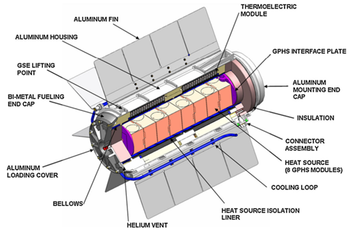
Figure 2. Cutting view of an MMRTG [16]
Figure 2. Cutting view of an MMRTG [16]
3.1.2. Power supply devices in remote areas
One of the first terrestrial use of RTGs was made in 1966 by the U.S. Navy for powering environmental instrumentation at Fairway Rock, a small uninhabited island in Alaska. RTGs were used at this site until 1995 [17]. These systems were developed for the power supply of equipment requiring a stable and reliable power source, over several years and without maintenance. Examples of these would be power supplies for systems located in isolated or inaccessible environments like lighthouses and navigation beacons, and weather stations. Similarly, between 1960 and 1980, the Soviet Union built many unmanned lighthouses and navigation beacons equipped with about 1,000 RTGs (Figure 3) [18]. All Russian RTGs have long exhausted their 10-year lifespan and require extreme dismantling measures due to the potentially dangerous source of radioactivity, and the risk of being used in terrorist acts [19]. Obviously, all research and development in this field has been stopped because of the risks already mentioned [20].
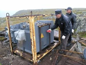
Figure 3. RTG used to supply power to lighthouses and navigation beacons [19]
Figure 3. RTG used to supply power to lighthouses and navigation beacons [19]
3.1.3. Medical domain
In 1966, small plutonium cells (very small RTGs fed with Pu238) were used in implanted pacemakers to ensure a very long battery life, as shown in Figure 4 [21]. In 2004, about 90 of them were still in use. Many companies have manufactured nuclear-powered pacemakers: ARCO (Perma-grain), Medtronic (Laurens-Alcatel), Gulf General Atomic, Cordis (Telektronic, Accuffix), American Optical, Technologie Biocontrol (Coratomic) and Medical Devices, Inc (MDI) [22]. After the development of lithium batteries, the market for nuclear batteries dried up [23].

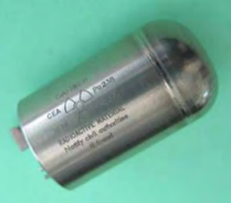
Figure 4. Left pacemaker and right RTG battery [21].
Figure 4. Left pacemaker and right RTG battery [21].
3.2. Natural heat source
3.2.1. Natural gas and biomass
Pouillet, in 1840, used the Seebeck effect in making a thermoelectric cell with a welded pair of bismuth and copper. The two solderings were immersed in two vessels, one containing melting ice and the other hot water [24]. This apparatus supplying a constant source of dynamic electricity was used by the author to investigate the general laws of currents [25].
At the same time several prototypes of thermoelectric batteries were built and even commercialized, with different sizes and materials for different purposes [26]. For instance, the Oersted and Fourier battery designed for their investigations [27], the Ruhmkorff Thermopile (1860) powered by gas and cooled with water [28], and the gigantic Clamond battery (1879), which was the first thermoelectric battery powered with coal or wood that could have been used in industry, with a height of 2.50 m and 1 m in diameter. Its maximum power was 192 Watts, at 54 Volts and 3.5 Amperes [29]. It is worthy of note that the most remarkable achievement was Melloni's Thermo-Multiplier built in 1830, which was an instrument for making very small amounts of sensitive heat. The battery consisted of about ten Bismuth-antimony pairs that were associated with a Nobili galvanometer. This instrument, was so sensitive that the galvanometer needle deflected by the effect of the natural heat of a person placed 10 m from the battery [30].
Nowadays thermopiles or TEG thermoelectric generators are designed to supply energy to autonomous sensors, installed in remote locations subject to severe environmental conditions i.e. very low temperature, and difficult access, where conventional renewable energy sources, such as solar and wind energy, are not regularly available. Heat is usually supplied by a flameless catalytic burner [31]. A few manufactures of thermoelectric generators powered by natural gas are installed in more than 55 countries. For instance, Gentherm manufactures TEGs with powers ranging from 15 to 550 W. These generators are mainly used on offshore platforms, along pipelines, at altitudes or near gas wells (Figure 5) [32]. Another example is Farwest Corrosion Control, a company that manufactures and installs TEGs for cathodic protection against pipe corrosion and has installed more than 15,000 generators in 51 countries [33].
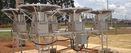
Figure 5. Gentherm Gas TEG [32]
Figure 5. Gentherm Gas TEG [32]
Several products designed for public use were marketed. One such was the thermoelectric candle radio (1990) which uses the heat from the candles to power the radio via a FeSi2 TE module [34]. These applications have become obsolete with the emergence of other more practical technologies, but despite that, there are still some specific applications, such as the CampStove shown in figure 6. This equipment, designed for camping in general, burns wood to produce 2 W of 0.4 A and 5 V power using a thermoelectric generator in which the connection of the electrical devices is made via a USB port [35].

Figure 6. Picture of a CampStove [35]
Figure 6. Picture of a CampStove [35]
3.2.2. Human body
As the heat of the human body is natural and stable, it could be used to supply some electricity in very specific applications, such as medical ones [36] [37]. The human body releases around 100 W of heat at rest and 525 W during physical effort [38].
Several investigations have been conducted into wearable thermoelectric generators (WTEGs) since 2001 [39] with the aim of substituting lithium-ion batteries [40] as a power source for portable devices, given that the global market for portable technologies is growing rapidly and is expected to exceed $34 billion by 2020 and $78 billion by 2021 [41]. WTEGs are classified according to their rigid or flexible (extensible or not) [42] architectures in 2D or 3D configurations [43], or in their TE component materials which are inorganic, organic or hybrid [44].
Leonov and Vullers [37] published an interesting review on WTEGs, focusing on rigid and flexible type thermoelectric generators. They concluded that the wearable thermoelectric generator style was mature and that the major concern was to improve the efficiency of the generator as well as to make it thinner and more flexible. These authors conducted extensive research on rigid substrate TEGs. They developed different WTEG products that used body heat, such as the wireless electrocardiography system integrated into an office shirt. This product was powered by 17 small TE modules integrated into the front side of a shirt as shown in figure 7. They converted the body's natural heat flow into electrical energy of 0.8 to 3 mW depending on the physical activity of the person [45].
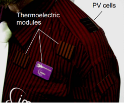
Figure 7. WTEG integrated into a shirt [45]
Figure 7. WTEG integrated into a shirt [45]
One of the leading companies in this field is IMEC (Belgium), which has been working on thermoelectric generation by people since the 2000s, with a view to power electronic health care systems. IMEC and the Holst Centre have developed several wireless sensors such as the Body-powered EEG Acquisition System that produces 2-2.5mW of power and is worn as a headband. shown in Figure 8(a) [46], and a wireless pulse oximeter (2006) powered entirely by a TEG style watch using commercial Bi
One of the leading companies in this field is IMEC (Belgium), which has been working on thermoelectric generation by people since the 2000s, with a view to power electronic health care systems. IMEC and the Holst Centre have developed several wireless sensors such as the Body-powered EEG Acquisition System that produces 2-2.5mW of power and is worn as a headband. shown in Figure 8(a) [46], and a wireless pulse oximeter (2006) powered entirely by a TEG style watch using commercial Bi
2
Te
3
thermopiles, shown in Figure 8(b), and in which the generator develops around 89µW of power [47].
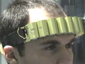

Figure 8. (a) TEG supplies power to an EEG system mounted on an expandable headband [46]; (b) Wireless pulse oximeter [47]
Figure 8. (a) TEG supplies power to an EEG system mounted on an expandable headband [46]; (b) Wireless pulse oximeter [47]
The first thermoelectric wristwatch powered by converting body heat into electrical power was marketed by Seiko and Citizen and dates back to 1999 [48] [49]. The Seiko watch (Figure 9(a)) produced 22 µW of electrical power and an open-circuit voltage of 300 mV with efficiency about 0.1% [50]. Another example is the Dyson TE bracelet (2012) shown in Figure 9 (b), which, using body heat, charged a battery integrated into it to charge a mobile phone or any other mobile device.
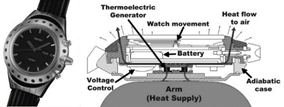

The first thermoelectric wristwatch powered by converting body heat into electrical power was marketed by Seiko and Citizen and dates back to 1999 [48] [49]. The Seiko watch (Figure 9(a)) produced 22 µW of electrical power and an open-circuit voltage of 300 mV with efficiency about 0.1% [50]. Another example is the Dyson TE bracelet (2012) shown in Figure 9 (b), which, using body heat, charged a battery integrated into it to charge a mobile phone or any other mobile device.
Figure 9. (a) Seiko Thermic, wristwatch [50]; (b) Dyson bracelet [51]
Figure 9. (a) Seiko Thermic, wristwatch [50]; (b) Dyson bracelet [51]
Because of the drawbacks of rigid modules, i.e. high thermal resistance between skin and TEG, flexible modules are more suitable for power generation from body heat, as they can be adapted to the shape of the body, thus increasing the useful surface area for heat capture and reducing thermal contact resistance [52]. Francioso et al. [36] developed a flexible and wearable micro thermoelectric generator composed of 100 array thin film thermocouples of Sb
Because of the drawbacks of rigid modules, i.e. high thermal resistance between skin and TEG, flexible modules are more suitable for power generation from body heat, as they can be adapted to the shape of the body, thus increasing the useful surface area for heat capture and reducing thermal contact resistance [52]. Francioso et al. [36] developed a flexible and wearable micro thermoelectric generator composed of 100 array thin film thermocouples of Sb
2
Te
3
and Bi
2
Te
3, designed to power very low consumption electronics ambient assisted living (AAL) applications. The best result obtained was 430 mV in open circuit, and an electrical output power up to 32 nW at 40 °C. KIM et al. [53] manufactured a flexible fabric-shaped TEG with 3D printing technology composed of 20 thermocouples and a thickness of 0.5 mm as shown in Figure 10(a). The TEG, when applied to a human body, generated an electrical power of 25 mV at an ambient temperature of 5 °C. A new approach was presented by Suarez et al. [54] using standard bulk legs interconnected to a stretchable low-resistivity eutectic alloy of gallium and indium (EGaIn), all in a flexible elastomer package as shown in figure 10(b). The authors reported a figure of merit (ZT) of 0.35, which they claimed to be better than that of any other similar device reported in the open literature. Zadan et al. [55] introduced a soft and stretchable thermoelectric generator (TEG) with the ability to expand, to explore the integration of this TEGs into wearable technologies. All investigations conducted so far have suggested that this option can only be viable at moderate temperatures, i.e. indoors in particular, and this limits its application together with the high cost of TE modules [56].
, designed to power very low consumption electronics ambient assisted living (AAL) applications. The best result obtained was 430 mV in open circuit, and an electrical output power up to 32 nW at 40 °C. KIM et al. [53] manufactured a flexible fabric-shaped TEG with 3D printing technology composed of 20 thermocouples and a thickness of 0.5 mm as shown in Figure 10(a). The TEG, when applied to a human body, generated an electrical power of 25 mV at an ambient temperature of 5 °C. A new approach was presented by Suarez et al. [54] using standard bulk legs interconnected to a stretchable low-resistivity eutectic alloy of gallium and indium (EGaIn), all in a flexible elastomer package as shown in figure 10(b). The authors reported a figure of merit (ZT) of 0.35, which they claimed to be better than that of any other similar device reported in the open literature. Zadan et al. [55] introduced a soft and stretchable thermoelectric generator (TEG) with the ability to expand, to explore the integration of this TEGs into wearable technologies. All investigations conducted so far have suggested that this option can only be viable at moderate temperatures, i.e. indoors in particular, and this limits its application together with the high cost of TE modules [56].
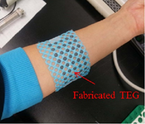
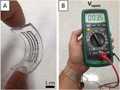
Figure 10. (a) Flexible TEG fabricated using dispenser printing technology [57]; (b). Flexible device and test configuration: (A) flexible device tested, (B) circuit voltage open at room temperature [54]
Figure 10. (a) Flexible TEG fabricated using dispenser printing technology [57]; (b). Flexible device and test configuration: (A) flexible device tested, (B) circuit voltage open at room temperature [54]
Soleimani et al. [58] have published a review on recent developments in inorganic, organic, and hybrid wearable TEGs. The authors concluded that inorganic TE materials remain favorable due to their high ZT (~1), but unfavorable due to their rarity, toxicity and impractical rigidity. Organic TE materials have high flexibility and non-toxic elements, but their weaknesses are low stability in air and complexity in the synthesis process. They reported that hybrid TE materials are the solution to the rigidity of inorganic TE materials and the low efficiency of organic TE materials. These hybrid TE materials are suitable for portable TEGs. Jiang et al. [59] presented a review focused on recent developments of TE materials concerning film- and fiber-based materials for flexible wearable applications. They concluded that these applications will eventually become a reality with the development of preparation technology for film or fiber legs, human thermoregulatory models for designing wearable devices, and integration with other wearable renewable energy conversion devices.
3.2.3. Sun source
A solar thermoelectric generator (STEG) is a system designed to recover heat from solar radiation and convert it into electricity using a thermoelectric generator (TEG). It is becoming a technological alternative and competing with the dominant solar photovoltaic systems despite its low conversion efficiency compared to PV technology [60]. STEGs are classified according to the type of optical sensors used, namely an optical concentration system or not. Optical concentration sensors are usually cylindrical lenses, Fresnel lenses, parabolic mirrors, flat mirrors or parabolic concentrators. Non-concentrated solutions are rather limited to flat plate collectors evacuated or not evacuated, and vacuum tubes [61]. Karthick et al. [62], in a recent review, reported that the use of optical concentrators combined with heat pipe tubes improves the efficiency of solar thermoelectric generators (STEG).
The first investigation into thermoelectric solar energy dates back to the end of the 19th century, with Weston's patent in 1888 [63][64] which combined a thermopile (TEG) with a mirror or lens to focus solar radiation on hot junctions and a storage battery. The first experimental data on a STEG device were published by Coblentz in 1922 [65] with an efficiency of less than 0.01%. More progress was reported in 1954 on a STEG device by Telkes [66] who demonstrated an efficiency of 0.63% and 3.35% at 1 × and 50 × sun respectively of the optical concentrators in a flat-plate solar energy collector. ZnSb-type alloys in combination with a negative Bi-alloy were used. The most significant investigations on solar thermoelectric generators (STEGs) are summarized in the following. He et al. [67] carried out a theoretical and experimental study on the integration of thermoelectric modules in solar vacuum tube heaters (SHP-TE) as illustrated in Figure 11. Their experimental data showed an electrical efficiency of 1%, which is slightly lower than a system with an organic Rankine cycle but according to the authors the SHP-TE system is simple and has no moving components and its units are easy to replace. On the same principle another creative investigation was done with the use of a parabolic solar concentrator [68][69].
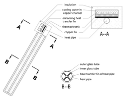
Figure 11. Schematic diagram of an integrated SHP-TE system [67]
Figure 11. Schematic diagram of an integrated SHP-TE system [67]
Kraemer et al. [70] used nanostructured thermoelectric materials to develop the solar flat panel thermoelectric generators shown in Figure 12. These TEs achieved a maximum efficiency of 4.6% under an irradiation of 1 kW.m -2. The efficiency was 7 to 8 times higher than the best value previously reported for a flat panel display.
Amatya and Ram [71] combined a commercial Bi2Te3 module with a parabolic concentrator (solar concentration of 66 x suns). A system efficiency of 3% was measured and an output power of 1.8 W was achieved. Rehman et al. [72] proposed a novel collector design for a solar concentrated thermoelectric generator. The system had an electrical efficiency of 1.45% and a maximum optical efficiency of 93.61%. Li et al. [73] evaluated a prototype consisting of a solar concentration thermoelectric generator (CTG) with Fresnel lens (Figure 13). Their results showed that the highest possible CTG efficiency could reach 9.8%, 13.5% and 14.1%, respectively, for Bi2Te3, skutterudite and LAST (silver antimony lead telluride) alloys.
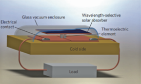
Figure 12. Illustration of a STEG cell consisting of a pair of thermoelectric elements type p and n [70]
Figure 12. Illustration of a STEG cell consisting of a pair of thermoelectric elements type p and n [70]
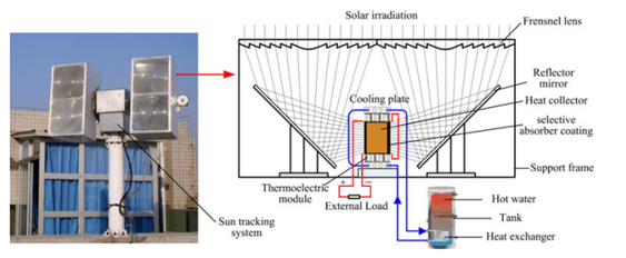
Figure 13. Concentrating Solar Thermoelectric Generators: (a) An experimental prototype of the Concentrating Solar Thermoelectric Generator System; (b) Details of the CTG unit [74]
Figure 13. Concentrating Solar Thermoelectric Generators: (a) An experimental prototype of the Concentrating Solar Thermoelectric Generator System; (b) Details of the CTG unit [74]
Photovoltaic and thermoelectric systems are the only processes that directly convert solar energy into electrical energy [75]. Some investigations were conducted on hybrid photovoltaic-thermoelectric systems [76] and concentrated photovoltaic (CPV)-thermoelectric systems [77]. Another hybrid system consists of the direct coupling of a solar water heater with a thermoelectric module, in order to improve the overall performance of the system producing heat and electricity simultaneously [78]. However, their combination is complex because of their opposing characteristics, as effective integration of the two systems is essential [79]. Sripadmanabhan Indira et al. [80] investigated different configurations of the hybrid system integrating photovoltaic concentrators (CPV) and thermoelectric generators (TEG) and outlined recommendations for future research. The authors reported that the integrated CPV-TEG based solar thermal systems have higher electrical and thermal performances than those of non-concentrated PV-TEG systems. Li et al. [81] compared a hybrid Photovoltaic-thermoelectric (PV-TE) system employing a micro-channel heat pipe array together with the PV electricity generation. The results showed that the electrical efficiencies of the hybrid PV-TE system were about 14% higher than those of the PV system.
Mizoshiri et al. [82] built a hybrid module composed of a thin-film thermoelectric module and a photovoltaic module. This hybrid module filtered light through an infrared filter (hot mirror) allowing only the light that contributed to photovoltaic conversion to pass through. At the same time, the reflected light was focused on the warm side of the thermoelectric module using a lens. The total no-load voltage of the hybrid thermo-photovoltaic generator showed an increase of 1.3% when compared with using the photovoltaic module alone. As regards TPV/TE hybrid systems, thermophotovoltaic cells (TPV) are capable of converting infrared radiation into electricity. They consist of a heat source, an emitter, a filter and photovoltaic (PV) cells [83]. Unlike photovoltaic solar panels, TPV cells are illuminated by radiant combustion sources. Given that the radiant power density of these sources can be much higher than that of the sun, the electrical power density of TPV cells is much higher than that of solar cells with an efficiency of 24.5% [84]. As of yet, few studies have been conducted into integrated TPV/TE systems. Qiu and Hayden. [85] reported that the efficiency of an integrated system with TPV GaSb cells and TEG was superior to that of individual TPV and TE. For this reason, the TPV/TE hybrid system is an interesting alternative system and further research is required in the future [86]. However, the major concern with hybrid systems is to achieve optimal hybridization, which means ensuring that the sum of the maximum powers produced separately by each PV and TE equals the power produced by the hybrid system [87].
3.3. Waste heat source
A huge amount of low-grade waste heat is released into the environment without any attempt at heat recovery. Over the last three decades much effort has been made to improve the efficiency of thermoelectric technology in heat recovery applications [88]. This is promoted by the fact that TE technology could be easily adapted to the physical parameters such as temperature, pressure, and heat transfer fluid of a given heat recovery application. Waste heat recovery using thermoelectric technology can be divided into two main groups as follows.
3.3.1. Waste heat recovery from industry and homes
Dai et al. [89] reported that in United States 33% of industrial manufacturing energy is released directly into the atmosphere or into cooling systems as waste heat, and this amount of heat could be used to produce 0.9 TWh to 2.8 TWh of electricity per year if thermoelectric materials with average ZT values ranging from 1 to 2 were available. Hence, there is a need for technical and economic studies to develop feasibility for large-scale applications that, in the medium and long term, would make it a competitive source of clean energy [90]. Zou et al. [91] demonstrated that municipal wastewater can be used to produce electricity using a thermoelectric generator (TEG). Their theoretical study performed for the Christiansburg Wastewater Treatment Plant, estimated energy generation of 1094 to 70,986 kWh per year with a saving of USD 163 to USD 6076. In another investigation that used an air-cooling heat recovery device with 120 mm square pipes, the wastewater recovery efficiency was 1.28% and the amortization period for the equipment extended to 8 years [92].
Araiz et al. [93] carried out a techno-economic study into the thermoelectric recovery of hot gases from a stone wool manufacturing plant. They reported a maximum net power production of 45 kW and a Levelized Cost of Electricity at about 0.15 EUR/kWh, which demonstrated the feasibility of the system. Mirhosseini et al. [94] performed a similar investigation using an arc-shaped absorber designed for thermoelectric heat recovery of waste heat from a rotary cement kiln. The economic evaluation showed that the dominant parameter in the system cost is the heat sink.
It is worth noting that heat recovery depends strongly on the ambient temperature. In hot regions, investigations were mainly focused on the recovery of heat released in air conditioning systems [95]. However, investigations on heat recovery were more diversified in cold regions. Killander and Bass [96] developed and tested a prototype of a thermoelectric generator designed to supply small amounts of electricity using heat from existing wood stoves in homes in the cold and isolated regions of northern Sweden. The cost of connection to the grid in this region ranged from USD 5,000 to USD 120,000 per house. The device provided sufficient energy for electric lighting and watching television during the long winter nights. In the Netherlands, Gasunie Research, an energy network operator, developed in 1999-2000, built and tested 20 autonomous (self-powered) boilers that used the heater flame produced to co-generate enough electricity to operate its electrical components using six HZ-20 thermoelectric modules [97]. They concluded that these thermoelectric generators supplied 60 W of electricity, which was enough to run their electrical components. Other tests were carried out in the United States of America and England [98] on residential scale hydronic central heating units that were modified with the addition of a thermoelectric production stage to demonstrate autonomous operation in a realistic environment. The thermoelectric stage is a set of 18 thermoelectric modules made of bismuth telluride alloy, which generates an electrical power of 109 W sufficient to supply the blower, the gas control and the water pump of the hydronic central heating. According to Sornek et al. [99], the commercial success of such an installation has to be focused on: (i) introduction of necessary modifications to the heating devices, (ii) the development of a dedicated structure of the TEG.
In the case of operating conditions in which ambient temperature is not as important as the arrangement of the system off-grid, Bass and Farley [100] tested three thermoelectric generators designed to provide electrical energy in a natural gas field. These generators converted the waste heat produced by the equipment used in the gas field into a thermal energy source for the generators. Electricity was used for cathodic protection, telemetry power supply and lighting. Also, the US military used thermoelectric technology to reduce the logistics of field feeding by integrating thermoelectric devices into the Assault Kitchen that was used to heat food rations out on the field. These devices had no need for an external electrical generator to power the Assault Kitchen. In addition, they produced an excess of electricity that could be used for lighting, battery charging, radio power, communication equipment, etc. [101].
3.3.2. Waste heat recovery from transport systems
3.3.2.1. Automobiles
The road transport in Europe represents about 20% of the total carbon dioxide emissions, 75% of which come from private cars, and similar rates are observed in America and Asia [102]. European regulations aim to achieve a CO2 emissions target of 95 g/km by 2021 and 68 g/km by 2025 for passenger cars and light commercial vehicles [103]. It is worth taking into account that two thirds of a vehicle's combustion energy is lost as waste heat, 40% of which is in the form of hot exhaust gas [104],[105]. If about 6% of exhaust heat could be converted to electrical energy, it would be possible to reduce fuel consumption by about 10% [106].
To this end, the major American, Asian and European automobile companies, in collaboration with research institutes and universities, are trying to develop various types of TEGs to improve the fuel economy of their vehicle models, to preserve and gain an additional share in the future automobile market, which will undoubtedly be more restrictive. Agudelo et al. [107] tested a diesel passenger car in a climatic chamber to determine the potential for energy recovery from exhaust gases. They concluded that the potential fuel savings ranged from 8% to 19% and the silencer showed the highest energy losses, so the installation of a TEG needed to be located prior to it. Moreover, there are mainly three possible locations for the TEG [102], namely: (i) The TEG is placed at the end of the exhaust system; (ii) TEG is located between the catalytic converter and the silencer, the best option; (iii) The TEG is located upstream of the catalytic converter and silent. If the weight of the installed TEG and the additional pressure drops in the exhaust system are not optimized, the vehicle will consume more fuel than it needs to save, and consequently the system becomes totally inefficient [108]. The different thermoelectric generators manufactured for automobiles (ATEG) can be compared depending on the shape, material or suitable heat transfer system.
In the late 1980s, Birkholt [109], in collaboration with Porsche, proposed a thermoelectric generator with a rectangular cross-section, which was able to produce up to 58 W under peak conditions with FeSi2 elements. At the end of the 1990s, Nissan Research Center from Japan [110] developed a TE generator with a rectangular cross-section of 72 modules. Each one of these modules contained 8 pairs of Si-Ge elements to be applied to gasoline powered vehicles. The electrical power supplied by the generator was 35.6 W. Later they tested a thermoelectric generator composed of 16 Bi2Te3 modules operating at low temperature; the electrical power generated by the generator was 193 W [111]. In 1992, Hi-Z Technology started the development of a 1 kW thermoelectric generator for diesel truck engines with funding from the U.S. Department of Energy and the California Energy Commission [112]. Amerigon (now Gentherm) developed thermoelectric generators for passenger vehicles between 2004 and 2011 in 5 phases. The project was sponsored by the US Department of Energy (DOE) and counted on the participation of BMW and Ford in Phase 3 and Faurecia in Phase 5. [113]. Phases 1 and 2 dealt with the tests of a low temperature liquid/liquid TEG that developed 500 W and was built with Bi2Te3 materials implanted in a flat plate TEG design [113] [114]. In phase 3, a two stage flat plate-shaped gas/liquid TEG at a high temperature (above 600 °C) consisting of TE elements segmented in two stages, and based on a half-Heusler alloy (Zr, Hf), was installed near the hot gas inlet and Bi2Te3 elements near the outlet. The measured output power resulted in about 100 W [113] [115]. During phases 4 and 5, a new cylindrical design was selected due to the limitations encountered with the flat plate design, and power output reached over 200 W in phase 4. In the final phase power output improvement was achieved on a BMW X6 (Figure 14), and a Lincoln MKT (Ford) with more than 600 W of power produced in vehicle tests and more than 700 W in bench tests [113] [116][117]. This success conducted Gentherm, BMW and Tenneco in 2011 to launch a new program of seven years using a new thermoelectric cartridge device. The electricity generated by the TEG could save fuel consumption by 2% which was far from the program's aims. General Motors developed a prototype by using Bi-Te and Skutterudite modules which was installed on a Chevrolet suburban [118]. The skutterudites used at high temperatures were their final choice. An average power developed by the TEG was expected to be 350 W for city driving cycles and 600 W on motorways [119]. In 2013, Fiat and Chrysler announced the manufacture of the first light commercial vehicle equipped with a TEG [120] with a fuel economy of 4%. The TEG used cross-flow architecture, with segmented TE elements of TAGS, Bi2Te3-PTe and Skutterudites. Another relevant development was called RENOTER [121], an association between Renault and Volvo involving 8 partners and was partially financed by the French government. This project was carried out with the aim of installing thermoelectric generators (the TEGs) in their car range.
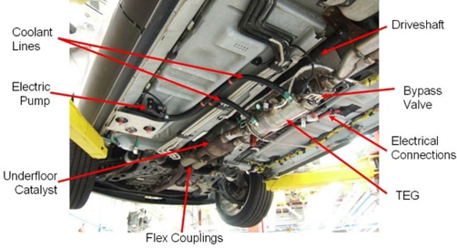
Figure 14. TEG integration into the exhaust line of the BMW X6 prototype vehicle [122]
Figure 14. TEG integration into the exhaust line of the BMW X6 prototype vehicle [122]
Bou Nader [123] proposed an innovative thermodynamic configuration and investigated the fuel-saving potential of hybrid electric vehicles using a thermoelectric generator system as an energy converter instead of the conventional internal combustion engine. Simulation results revealed a 33% higher fuel consumption with the chosen thermoelectric generator configuration compared to the conventional internal combustion engine. This investigation highlighted the importance of increasing the thermoelectric generator module figure of Merit in order to achieve system efficiency comparable to the internal combustion engine. This energy converter has a potential for implementation in future powertrains with zero carbon alternative fuels. Recently, Shen et al. [122] presented the current status, challenges and future prospects of automotive exhaust thermoelectric generators. The authors cited eleven challenges to overcome before the possibility of commercial applications. These are mainly the low efficiency of the TEG, insufficient heat extraction capacity and non-uniform temperature distribution on the exhaust side, and space limitation.
3.3.2.2. Motorcycles
Motorcycles are the most commonly used means of transport in some countries such as Indonesia. Septiadi et al. [124] investigated the usefulness of installing a thermoelectric generator on the exhaust of a motorcycle. Their results showed that the output voltage reached was 15.7 V and 7.7 V for TEGs of 4 modules and 2 modules, respectively. In 2013, ATSUMITEC, in cooperation with the Nagoya Institute of Technology, applied the Heusler module to the underpower generator of a motorcycle [125], by integrating the thermoelectric device with a fuel cell as illustrated in Figure 15. The fuel cell produced energy from trace quantities of spent fuel in the exhaust gases. The temperature difference between heat from the exhaust gases and heat generated by the chemical reaction in the fuel cell was used to generate power by means of the thermoelectric device. The total output power of fuel cell plus the thermoelectric power was 400 W [126]. Schlichting et al. [127] tested the feasibility of installing a TEG on a motorcycle, with the aim of replacing the alternator with a TEG unit. They used 570 modules to match the alternator output. They concluded that the potential of replacing the alternator with TEG units was quite low.
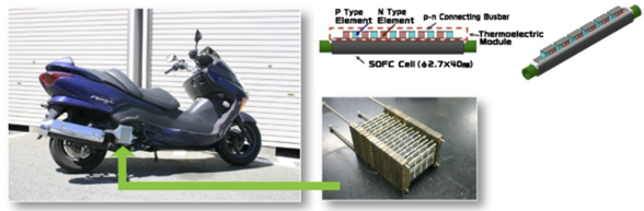
Figure 15. TEG installed in the exhaust gases of a motorcycle [125]
Figure 15. TEG installed in the exhaust gases of a motorcycle [125]
3.3.2.3. Aircraft
Modern aircraft are increasingly equipped with sensors and transmitters for better control and monitoring and greater safety. The supply of power to these sensors via power lines would result in additional heavy wiring, causing additional fuel consumption. The use of thermoelectric generators to power such instruments is one of the most promising approaches. The implementation of autonomous wireless sensor networks, would lead to a reduction in aircraft weight and complexity, thus reducing fuel consumption.
Boeing Research & Technology estimated that a 0.5% reduction in fuel consumption would be translated into a $12.075 million reduction in monthly operating costs for U.S. commercial aircrafts and approximately 0.03% reduction in carbon emissions for U.S. passenger aircrafts, taking into account that aircraft contribution to global carbon emissions is approximately 2% [128]. A recent study carried out in the framework of the German Aeronautical Research Program (LuFo-5) on the performance of a thermoelectric generator, integrated between the hot part of a propeller and the bypass flow of the cooler demonstrated that the efficiency of the TEG ranged from 3% to 7% with a power of 1 kW/m2 to 9 kW/m2 depending on its location in the various hot parts of the propeller [129]. Lyras et al. [130] designed a TEG to be installed between the inside and outside walls of the aircraft, since the fuselage is exposed to extremely low temperatures (~ -50 ºC) [131], while the inside of the aircraft has a controlled temperature (~ +20 ºC) for passenger comfort. Some sensors such as the stress sensor [132], which controls the state of health of the hull, must be installed on different parts of the aircraft. Therefore, it would be very useful to be able to use a TEG attached directly to the fuselage and combined with a phase-change material (PCM) heat storage unit. This would create a temperature gradient during takeoff and landing, which could generate electricity to power a Node of autonomous low-power wireless sensors [133][134]. The system was successfully integrated and functionally tested, qualifying it for use in a flight test facility [132].
Helicopters have also been considered through a study on the feasibility of recovering helicopter exhaust gases using thermoelectric modules. The results of this study showed that the electrical energy produced under real operating conditions was significant but currently insufficient, particularly if we take into account the weight/power ratio [135].
3.3.2.4. Ships
There is scarce research reported on thermoelectric recovery of lost heat from ships in the open literature. Maritime shipping alone represents about 2.8% of greenhouse gases in the world [136]. Moreover, the integration of thermoelectric power generation in ships is more advantageous than in other transportation systems because cooling water is fully available. The integration of thermoelectricity in this sector is almost inexistent because of the absence of strict international regulations, imposing permissible pollution rates for ships, unlike the automotive sector. The European Union is currently planning measures to reduce emissions from international maritime transport, so the introduction of new and stricter rules should increase the rate of research.
A project called ECOMARINE, co-financed by the European Union (European Social Fund) and Greek national funds, was carried out to implement a thermoelectric energy recovery unit with the aim of maximizing electricity production by waste heat recovery, and simultaneously improving the quality of electrical energy. In this context, Loupis et al. [137] developed a tubular TEG with a diameter of 500 mm, which ensured a very low pressure drop of the exhaust gas flows during their passage through the RTG. The authors reported a conversion efficiency of 6.4%, a waste heat recovery of 1.2%, and an electricity supply of 20.3 kW.