The charging infrastructure has a key role in the implementation of battery electric buses (BEBs) in cities. BEBs only use off-board chargers, whereas the PEC to convert the three-phase AC power from the grid into DC power to charge the battery is located outside the BEB. These chargers allow higher charging power levels because they are not restricted in size and weight. Furthermore, since the driving range of a BEB is limited, a specific charging concept and interface is required to keep the BEB running during the day. This entry gives an overview of the existing charging interfaces and concepts and charger and PEC topologies to provide a reliable and efficient charging behavior.
1. Charging Interfaces
The on-board battery of BEBs needs to be charged regularly. Therefore, a BEB is equipped with a charging interface that can be connected to the appropriate charging infrastructure to charge the battery with power from the grid. Different charging interfaces exist, as depicted in Figure 13.
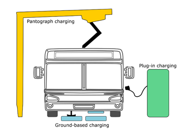
Figure 1. Overview of charging methods for BEBs.
-
Pantograph charging: A common way to charge BEBs is by using a pantograph that makes contact between the bus and the charging infrastructure in an automated way. Currently, there are two ways to perform this contact. The pantograph can be mounted on top of the roof of the BEB and is lifted when charging is required, or the pantograph is mounted on the charging infrastructure and moves downwards. The latter is preferable because it requires less pantographs for a given bus route and adds less weight to the BEB. Furthermore, the pantograph is not exposed to vibrations from the bus [21].
-
Plug-in charging: BEBs also can get charged by plugging in a connector from the charging infrastructure. Currently, the connector still needs to be plugged in manually, which makes this type of charging interface less attractive for larger BEB fleets. However, this process will also become automated through robotization in the near future [22].
-
Ground-based charging: In some cases, BEBs are getting charged through a ground-based charging system. This can be realized in two ways. Like pantograph charging, a current collector can be dropped down from the bus to contact a conductive device embedded in the road surface [23]. Another way is to transfer the charging power wirelessly by applying an electromagnetic field between a transmitting coil on the road surface and a receiving coil positioned on the BEB. The main advantage of wireless charging is that it can enable BEBs to charge while in motion [24][25].
2. Charging Concepts
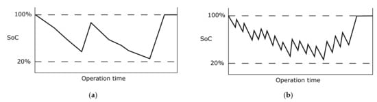
The three most promising charging concepts are depot charging, opportunity charging and dynamic wireless charging. Each of them serves different needs, depending on the characteristics and requirements of the bus network in cities, and each has its advantages and disadvantages. With depot charging, as the name suggests, the BEBs are only charged inside the depot. This mostly happens overnight (which is why this is often referred to as overnight charging), but because of the limited range of BEBs compared with their diesel counterpart, charging might also happen once during the daytime. This is illustrated in Figure 2a, which shows an example of the bus battery SoC throughout the day. On the other hand, opportunity charging refers to charging on-route, at end terminals or at regular bus stops. As such, the BEB is regularly charged during the day, without having to get fully charged each time, as highlighted by the evolution of the SoC throughout the day in Figure 2b. Dynamic wireless charging is in fact a special case of on-route charging, where the BEB gets charged while it is driving on specific road sections that are equipped with inductive charging pads. The daily SoC evolution dynamic wireless charging resembles opportunity charging (see Figure 2b).
Figure 2. Typical SoC profile of a (a) depot charging BEB and (b) opportunity and dynamic wireless charging BEB.
Typically, BEBs using depot charging have a large battery pack to ensure that they can be operated during a considerable portion of the day without having to return to the depot. The downside is that a larger battery increases the weight of the bus and requires more space, meaning that there is less space for passengers. Therefore, bus routes with a very high vehicle demand during peak hours need to employ depot charging outside of peak hours and use their large battery size to cover the entirety of the peak-hour duration
[1][26]. The charging power is often not higher than 150 kW (slow charging for BEBs) since there is enough time to charge the BEBs fully. For opportunity charging, it is the other way around, the size and weight of the battery can be reduced, which is why this type of charging is preferred for articulated (18 m) buses. The charging power can go up to 600 kW to sufficiently charge the BEBs in 5–10 min. As a result, opportunity charging at end terminals is often preferred by bus operators because at regular bus stops there is often no time to charge. In such a case, the charging power should be increased even more, which will result in very expensive chargers. For dynamic wireless charging, the size of the battery can be reduced even more, depending on how many inductive pads are installed under the road surface
[2][27]. The charging power can also be reduced if the dedicated road sections are long enough. Still, this charging concept is very expensive to build, since the roads need to be completely reconstructed.
Currently, depot charging has the highest market share, although several studies
[3][4][28,29] show that opportunity charging has lower lifecycle costs. However, with the decreasing battery cost, depot charging could reach a similar, or even lower, lifecycle cost. Another reason why bus operators might prefer this depot charging is that the charging infrastructure can be installed on their own property and can be centralized in one place. Furthermore, all types of BEBs can be charged here, no matter what their charging interface, although there is an increased interest in pantograph charging because of its potential to be automated. For opportunity charging, only pantograph or ground-based charging can be used. Either way, it is expected in the future that a mixture of both charging concepts will prevail because of the high diversity of bus routes in cities around the world. Dynamic wireless charging, on the other hand, is currently not yet implemented for BEBs and will presumably only be applied for bus-only lanes in the future.
Table 1 gives an overview of the different commercially available chargers for BEBs.
Table 1. Specifications of commercially available chargers for BEBs.
Manufacturer
Model |
Rated Power (kW) |
Charging Concept
Interface |
Output Voltage
(V) |
Efficiency
(%) |
ABB
HVC PU [5][6][30,31] |
100/…/600 |
Opportunity and depot charging
Pantograph and plug-in |
150–850 |
94–96% |
ABB
Terra 94/124/184 [5][30] |
90/120/180 |
Depot charging
Plug-in |
150–920 |
>95% |
Ekoenergetyka
charger [7][32] |
200/600 |
Opportunity charging
Pantograph |
150–950 |
>95% |
Ekoenergetyka
Plug Charger [7][32] |
20/…/150 |
Depot charging
Plug-in |
150–950 |
>95% |
Heliox
Opportunity Charger [8][33] |
450/600 |
Opportunity charging
Pantograph |
460–800 |
96% |
Heliox
Flex [9][34] |
180/360 |
Depot charging
Pantograph and Plug-in |
200–1000 |
95.5% |
IPT
Charge Bus [10][35] |
100/200/300 |
Opportunity and depot charging
Wireless ground-based |
400–750 |
>92% |
Jema
ECI series [11][36] |
50/…/200 |
Depot charging
Pantograph and Plug-in |
480–800 |
96% |
Jema
Opportunity chargers [12][37] |
350/500/600 |
Opportunity charging
Pantograph |
400–850 |
96% |
Kempower
C800 series [13][38] |
40/…/480 |
Depot charging
Plug-in |
200–920 |
>95% |
Siemens
Sicharge UC Charging center [14][39] |
100/150/300 |
Opportunity and depot charging
Pantograph and plug-in |
10–1000 |
>96% |
Siemens
Sicharge UC High power charger [14][39] |
450/600 |
Opportunity charging
Pantograph |
10–1000 |
>96% |
XCharge
C6 [15][40] |
60/…/160 |
Depot charging
Plug-in |
<1000 |
97% |
3. Charging Infrastructure Topology
3. Charging Infrastructure Topology
An off-board charger generally consists of a transformer, a harmonic filter and a PEC with a control and communication unit. The transformer provides galvanic isolation between the BEB and the grid. The filter is used to eliminate unwanted harmonic currents. The PEC converts the three-phase AC power from the grid into DC power used for charging the battery of the BEB. The control unit operates the switches of the PEC to adjust the voltage and current level to what the BEB can accept. The communication between the BEB and the charger is done based on the standard ISO 15118.
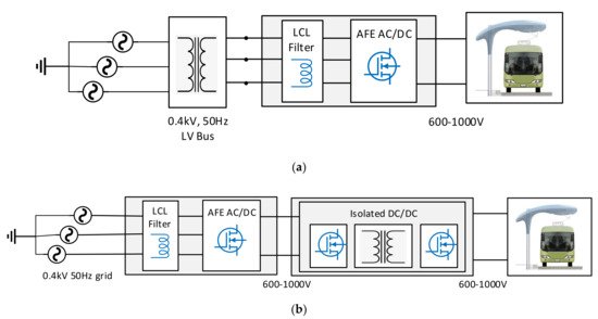
To ensure a safe operation of the charger, since it is characterized by high voltages and currents, galvanic isolation between the electrical grid and the BEB is required. This can be realized by two transformer topologies, as shown in Figure 3: a low frequency transformer (LFT) or a high-frequency transformer (HFT).
Figure 3. Topologies for BEB charging infrastructure with (a) LFT- and (b) HFT-based isolated DC/DC converter.
Figure 3a depicts a BEB charging station with an LFT between the electrical grid and the actual charger. Hence, the LFT is used to supply three-phase power to the charger. This bulky line frequency transformer increases the size and weight of the charger and complicates the installation. In addition, prominent conductors and bulky protection devices are required to deal with the high power. To overcome these issues, the operating frequency can be increased, which is realized through an isolated DC/DC converter, as depicted in
Figure 3b
[16][41]. The first stage consists of an AC/DC rectifier with a high voltage DC link. The second stage contains the HFT in the form of a solid-state transformer (SST) or power electronic transformer. In some cases, the HFT can also be part of the first power converter stage to create a low voltage DC link between the first and the second stage. A design with three stages with both a high-level and a low voltage DC link, and the HFT in between can also be considered
[17][42].
Currently, the available charging infrastructure on the market uses LFTs, because they are more reliable than STTs. Furthermore, they are more efficient, less costly, and compatible with the protection that is used in the grid today. Nevertheless, STTs remain a promising alternative because apart from their size and weight reduction, they also enable full control of the voltage and the current, and hence allow power quality improvement
[18][19][43,44]. Therefore, the design of STTs has been frequently addressed in the scientific literature. An overview of the state-of-the-art is provided in
[20][21][45,46].
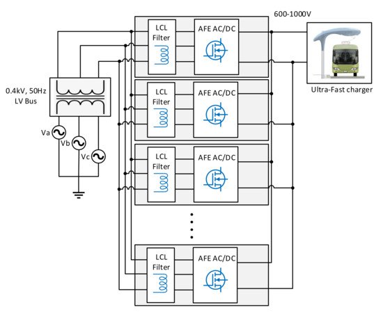
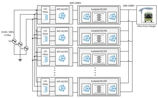
Because of the high power that is required for charging BEBs, especially for opportunity charging, often multiple identical PECs that are connected in parallel to a DC bus are integrated in the charging infrastructure, as illustrated in
Figure 4 in the case of a LFT, and
Figure 5 in case of an HFT. Such a modular approach increases the efficiency, the reliability and the flexibility of the system
[22][47]. In this way, BEBs that accept a different charging power level can use the same charging infrastructure by up- or downscaling the power level through the operation of a different number of PECs. Furthermore, the presence of the DC bus allows the integration of energy storage systems (ESS) and renewable energy resources (RES)
[23][48]. In depots, the modular approach can also be extended by integrating all the PECs in one charging cabinet from where multiple charging points are controlled. The charging points can then be installed at a certain distance from the charging cabinet, thus increasing the flexibility in terms of the configuration.
Figure 4. BEB charging infrastructure with LFT and modular PECs.
Figure 5. BEB charging infrastructure with HFT and modular PECs.
4. Power Electronic Converter Topology
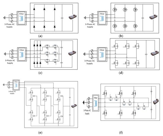
The most essential components of a PEC are the switches. At charging stations, the switches of the PEC convert AC power into DC power, allowing BEBs to connect and charge their batteries. The AC/DC conversion stage can be realized through an active front-end (AFE) converter. Several topologies exist to establish a three-phase AFE AC/DC PEC. It can include a diode bridge rectifier, a thyristor bridge rectifier, a Vienna rectifier, an active two-level buck/boost rectifier, or an active three-level rectifier as shown in
Figure 6 [16][24][25][41,49,50]. The simplest and most cost-effective approach for the AC/DC conversion is a diode rectifier. However, the fixed output voltage depends heavily on the three-phase supply voltage and it induces an unfavorable total harmonic distortion (THD). Implementing a Vienna rectifier can enhance the THD of the line current, but it has a limited reactive power control. These topologies, however, only allow a unidirectional power flow and can therefore not be used for vehicle-to-grid (V2G) applications. For a bidirectional power flow, a two- or three-level rectifier should be used. The two-level rectifier is widely used because it has a simple structure, it is easy to control through PWM and it generates low-harmonic currents. A three-level converter delivers even better performance in terms of system harmonics, but it also has an increased number of switches, resulting in an increased cost, size, and weight. Among all the described three-phase AC/DC conversion topologies, the two-level AFE boost rectifier,
as shown i
n Figure 8d, is the best option for a charger of BEBs, since from the design point of view, it is necessary to attain a high efficiency, a high-power factor, a cost-effective system with a reduced size and weight, a distortion-free operation with a limited grid impact and a high reliability.
Figure 6. Three-phase AFE converter topologies; (a) Diode bridge rectifier, (b) thyristor bridge rectifier, (c) Vienna rectifier, (d) Two-level active front end rectifier, (e) Three-level NPC type converter, (f) Three-level T-type AFE converter.
Nowadays, the switches inside the PECs used in the charging infrastructure for BEBs are mainly based on silicon (Si) IGBT semiconductor technology. However, recent advancements in the switching technology have contributed to the development of wide bandgap (WBG) semiconductor materials such as Silicon Carbide (SiC) and Gallium Nitride (GaN). These new WBG semiconductors enable the development of PECs that are more compact and efficient, and that can operate at higher voltages, higher frequencies and higher temperatures, compared with Si-based semiconductors
[26][51]. For high-power applications, such as BEB chargers, SiC-based switches will mainly be used because of their lower conduction voltage drop and their higher thermal conductivity, which leads to a significant reduction in the power losses
[27][52].