Your browser does not fully support modern features. Please upgrade for a smoother experience.
Please note this is a comparison between Version 1 by Dae Woo Kim and Version 2 by Camila Xu.
The organic solvent nanofiltration (OSN) technique has attracted significant attention in separation processes in the chemical and pharmaceutical industries because it can serve as an integrated system, has high energy efficiency at mild operating conditions. Nanoporous graphene has been used for OSN membrane fabrication and ultrafast solvent permeance with precise molecular separation has been demonstrated.
- graphene
- nanopore
- organic solvent nanofiltration
1. Introduction
The organic solvent nanofiltration (OSN) technique has attracted significant attention in separation processes in the chemical and pharmaceutical industries because it can serve as an integrated system, has high energy efficiency, and exhibits minimal degradation at mild operating conditions [1][2][1,2]. In contrast to gas and water separation membranes, OSN membranes must be stable in harsh organic solvents with precise selectivity for small molecules in the nm or Å scales. Thus, graphitic materials such as graphene, graphene oxide (GO), reduced graphene oxide (rGO), and graphene oxide nanoribbons (GONRs) have been used for membrane fabrication because of their excellent chemical stability and mechanical properties, owing to the strong sp2 hybridization of carbon atoms [3][4][5][6][3,4,5,6]. The one-atom-thick, two-dimensional (2D) shape of graphene with a high aspect ratio enables the deposition of an ultrathin selective layer on a porous support, resulting in a high solvent flux. Large-scale fabrication of graphene membranes can be done using continuous coating methods, such as slot-die coating and bar-coating [7][8][9][10][7,8,9,10]. In addition, molecular separation can be achieved by either a narrow interlayer spacing or nanopores on the basal plane.
Because of the aforementioned reasons, conceptual research on using graphene-based membranes for water treatment has been widely conducted, and a similar approach has been applied to OSN processes [11][12][13][11,12,13]. However, graphene layers are intrinsic barriers that also prevent the permeation of hydrogen and helium; therefore, the low permeation of organic solvents has been reported without any structural modification [14][15][14,15]. Thus, numerous approaches have been attempted to enhance the OSN performance by modifying the graphene structure. The application areas of the OSN process have been thoroughly discussed in previous studies; therefore, this review focuses on the current techniques used for tailoring the pore structure of the graphene layer and its effect on the OSN performance. Future perspectives of NG and current challenges faced are also discussed.
Recently, several graphene-based membranes that are used for water treatment or gas separation have been reported [16][17][18][19][20][16,17,18,19,20]. While single-layer nanoporous graphene (NG) membranes have been reported for their significantly thin selective layers, GO-based membranes have been reported, owing to their easy fabrication and precise molecular separation by narrow interlayer spacing. Compared to the research on water treatment membranes, the research on graphene-based OSN membranes is at an early stage. When only graphene is used for membrane fabrication, three approaches can be classified depending on their membrane structure: single-layer NG, multilayer graphene laminates, and multilayer NG laminates (Figure 1).
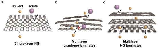
Figure 1. ThreeThree categories of graphene-based membrane used for OSN: categories of graphene-based membrane used for OSN: (a) single-layer NG, (b) multilayer graphene laminates, and (c) multilayer NG laminates.
2. Methods for Introducing Nanopores in Graphene
Intrinsically, pristine single-layer graphene is a barrier that prevents the permeation of small molecules, including helium (He), hydrogen (H2), and water. This is ascribed to the high electron density of its aromatic rings in the basal plane [14][15][21][14,15,21]. In addition, when GO is reduced to rGO, the effective interlayer spacing of rGO is negligible, and, thus, the small gas molecules do not penetrate the barrier [22]. The interlayer spacing of GO can be tuned by changing the type of organic solvent and the degree of swelling (Figure 1b); however, the molecules of the organic solvent are larger than those of water, and, thus, the permeation resistance to organic solvents can be much higher than to water. Therefore, a low or barrier-like organic solvent permeance was reported using a GO-based membrane, which can be beneficial for the dehydration of organic solvents [23][24][23,24].
Nanopore generation is a direct and effective method for enhancing the solvent permeance of graphene-based membranes. For single-layer graphene prepared by chemical vapor deposition (CVD) (Figure 1a), various top-down methods, such as focused ion beam, focused electron beam, ultraviolet-induced oxidative etching, ion bombardment followed by chemical etching, and oxygen plasma etching, have been used [25][26][27][28][29][25,26,27,28,29]. After transferring the CVD-grown graphene layer to a porous support, nanopores can be introduced by physical or chemical etching. For example, accelerated gallium ions generate defects on the plane, and further strong etching enlarges the pores (Figure 2a). As shown in Figure 2b,c, the formation of randomly distributed nanopores on the graphene layer can be confirmed by scanning transmission electron microscopy (STEM). By varying the exposure time in the chamber, the pore size and density of the nanopores can be tuned, as confirmed by the increased intensities of the D and D’ peaks in the Raman spectra (Figure 2d,e). Because single-layer or few-layer graphene is used as the selective layer, the membrane thickness can be significantly decreased to the atomic scale. However, as such processes are performed under high-vacuum conditions and post-treated in a chamber, most studies are limited to a small-scale fabrication, while Yang et al. demonstrated its fabrication up to cm-scale [30].
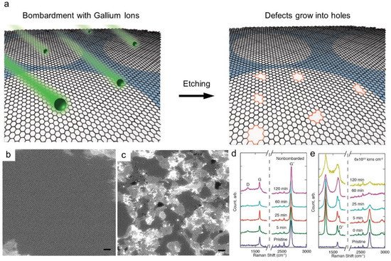
Figure 2. MembraneMembrane made of CVD-grown single layer graphene made of CVD-grown single layer graphene (a) Nanopore generation by ion bombardment followed by chemical oxidation. (b,c) TEM image of single layer graphene (b) and after (c) ion bombardment. Scale bars are 1 nm. (d,e) Raman spectra depending on chemical etching time and ion bombardment [25]. Copyright 2014 American Chemistry Society.
As an alternative method, the nanopores can be generated in GO on a large scale by post-treatment of GO powder; some examples of post-treatments are MnO2 etching, KOH activation, H2O2 treatment, and rapid thermal treatment [31][32][33][34][35][31,32,33,34,35]. Intrinsic defects and holes are present in the original GO, formed during the synthesis of GO, but the size and density of the pores are negligible and not controlled. Because such post-treatments generate nanopores by the decomposition of oxygen-functional groups or defective sp2 carbon on the GO plane, dense sp3 carbon is formed near the pores, and oxygen-functional groups are also partially present. The defective structure is critical to tune the interlayer spacing to enable the permeation of large organic solvents through the nanochannel. Moreover, because NG is soluble in water and organic solvents, it is beneficial to fabricate laminated membranes by solution processes such as vacuum filtration, spin coating, bar coating, spray coating, and slot-die coating (Figure 1c). As observed by transmission electron microscopy (TEM), the size of most nanopores generated by post-treatment was in the range of several nm, while the sizes of the sub-nm-sized micropores can be determined by gas adsorption. The pore size distribution of NG after post-treatment is typically broad; thus, the development of a more precise pore control method is required for the fabrication of highly selective membranes. On the other hand, the bottom-up synthesis of NG has also been attempted by surface-assisted aryl-aryl coupling reactions. However, membranes cannot be fabricated using synthesized graphene because the sheet is insufficient for deposition on a porous support. Thus, the achieved quality of exfoliation of graphene is unsatisfactory [36].
3. OSN Performance of NG-Based Membranes
The latest 2D material-based membranes and their OSN performance, including solvent permeation, solute rejection, and molecular weight cutoff (MWCO), are summarized in Table 1. The material types are categorized into transition metal carbides and nitrides (MXenes), transition metal dichalcogenides (TMDs), covalent organic frameworks (COFs), metal organic frameworks (MOFs), layered double hydroxides (LDHs), boron nitride, and NG-based membranes. All these membranes included a common thin-film composite-type membrane in which a selective graphene layer was fabricated on a porous support. Because the graphene layer is typically thin, on the nm scale, an additional freestanding porous support is essFiguretial for ensuring the mechanical stability of the membranes. Although the size and density of the porous support can affect the OSN performance, we focused on the material type of the selective layer, considering the optimized performance under each condition. As the viscosity of the solvent is inversely proportional to the permeance, the filtered solvents are also listed in the table. The details of the NG-based membrane are discussed below.
Table 1.
Summary of the organic solvent nanofiltration performance of 2D material-based membranes.
| Type | Material | Permeance | (a) | Rejection | (b) | MWCO | (c) | Fabrication Method | Filtered Solvent | REF | |||
|---|---|---|---|---|---|---|---|---|---|---|---|---|---|
| MXene | Ti | 3 | C | 2 | Tx | 982.7 | AY79 (100%) | 992 | Vacuum filtration | Isopropanol | [37] | ||
| PAN/PEI-Ti | 3 | C | 2 | T | x | -NH | 2 | 3 | PEG800 (96%) | 200 | Drop casting | Isopropanol | [38] |
| Ti | 3 | C | 2 | T | x | /CNTs-CTAB | 60.8 | CR (>95%) | 697 | Vacuum filtration | Ethanol | [39] | |
| TMD | S-MoS | 2 | 636 | MnB (99%) MB (100%) | 320 | Vacuum filtration | Isopropanol | [40] | |||||
| D-MoS | 2 | 109 | MnB (98%) BF (100%) | 320 | Vacuum filtration | Isopropanol | [40] | ||||||
| WS | 2 | -NMP-15 | 44.4 | EB (99%) RBB (91.5%) | 627 | Pressure-assisted filtration | Ethanol | [41] | |||||
| (3PEI/5PSS-2.5MoS | 2 | ) | 1.5 | 3.4 | MnB (93.4%) | 320 | Layer by layer | Ethanol | [42] | ||||
| COF | TAPA-TFP | 127.3 | BBR (94.8%) | 826 | Interfacial reaction | Ethanol | [43] | ||||||
| GO/COF | 50.8 | MnB (99%) CR (99.8%) | 320 | Vacuum filtration | Ethanol | [44] | |||||||
| SWCNT/COF | 60.5 | BBG (93%) | 854 | In-situ growth | Acetone | [45] | |||||||
| MOF | Zn-TCPP (Fe) | 140 | BBG (90%) | 854 | Vacuum filtration | Isopropanol | [46] | ||||||
| LDH | Mg-AlLDH | 651 | AF (99.6%) MO (98.3%) | 327 | Vacuum filtration | Acetone | [47] | ||||||
| NiS | 2 | /Ni-AlLDH | 2464 | MO (99.9%) | 327 | Vacuum filtration | Acetone | [48] | |||||
| BN | FBN-2 | 330 † | CR (>99%) | 697 | Vacuum filtration | Ethanol | [49] | ||||||
| FBN-8 | 240 † | MnB (93%) | 320 | Vacuum filtration | Methanol | [49] | |||||||
| Single-layer NG | Defect-sealed NG | 170.7 | RB (97.3%) | 826 | CVD | Methanol | [50] | ||||||
| 50.9 | RB (95.9%) | 826 | CVD | Ethanol | [50] | ||||||||
| Multilayer graphene | TPP/GO/HPEI | 8.5 | AB (95%) | 1299 | Pressure-assisted filtration | Ethanol | [51] | ||||||
| PA/cGO/cross-linked PI | 4.9 | EY (100%) RhB (99.3%) | 479 | Immersion | Ethanol | [52] | |||||||
| CW-GO | 58.1 | EB (96%) | 248 | Vacuum filtration | Methanol | [53] | |||||||
| GO-Si2 | 290 | RB (91.9%) CR (95.8%) | 697 | Vacuum filtration | Methanol | [54] | |||||||
| GO-0.5BA-T | 4 | AF (95.8%) | 586 | Vacuum filtration | Methanol | [55] | |||||||
| rGO-TMPyP | 0.6 | -44 | 5.3 | EB (>99.9%) AF (92.2%) | 586 | Vacuum filtration | Methanol | [56] | |||||
| GO/EDA | 0.5 | VB (95.3%) | 837 | Pressure-assisted filtration | Isopropanol | [57] | |||||||
| Shear-aligned GO | 130 | RhB (91%) | 974 | Gravure printing | Isopropanol | [58] | |||||||
| Micro & nanosized GO | 109.5 | MnB (98%) FB (91%) | 338 | Vacuumfiltration | Isopropanol | [59] | |||||||
| PI/GO | 107.8 | OII (96.3%) RB (99.9%) | 350 | Pressure-assisted filtration | Acetonitrile | [60] | |||||||
| Multilayer NG | TNCS | 1839 | NBB (99%) | 600 | Vacuum filtration | Isopropanol | [32] | ||||||
| NG-200 | 241 | EB (99.9%) CR (98.9%) | 616 | Vacuum filtration | Isopropanol | [61] |
AY79, Acid yellow 79; CR, Congo red; PEG, polyethylene glycol; MnB, methylene blue; MB, methyl blue; BF, basic fuchsin; EB, Evans blue; RBB, Remazol brilliant blue R; BBR, Brilliant blue R; BBG, Brilliant blue G; AF, Acid fuchsin; MO, Methyl orange; AB, Alcian blue 8GX; EY, eosin yellow; RhB, Rhodamine B; VB, Vitamin B12; FB, Fuchsin basic; OII, Orange II; NBB, naphtol blue black. PAN, polyacrylonitrile; PEI, polyethyleneimine; CTAB, Cetrimonium bromide; PSS, poly(sodium 4-styrenesulfonate; TAPA, tris(4-aminophenyl)amine; TFP, 2,4,6-triformylphloroglucinol; TCPP, tetra(4-carboxyphenyl)porphyrin; FBN, functionalized boron nitride; HPEI, hyperbranched polyethyleneimine; PI, polyimide; TNCS, turbostratic nanoporous carbon sheet. (a) Pure organic solvent permeance (L m
AY79, Acid yellow 79; CR, Congo red; PEG, polyethylene glycol; MnB, methylene blue; MB, methyl blue; BF, basic fuchsin; EB, Evans blue; RBB, Remazol brilliant blue R; BBR, Brilliant blue R; BBG, Brilliant blue G; AF, Acid fuchsin; MO, Methyl orange; AB, Alcian blue 8GX; EY, eosin yellow; RhB, Rhodamine B; VB, Vitamin B12; FB, Fuchsin basic; OII, Orange II; NBB, naphtol blue black. PAN, polyacrylonitrile; PEI, polyethyleneimine; CTAB, Cetrimonium bromide; PSS, poly(sodium 4-styrenesulfonate; TAPA, tris(4-aminophenyl)amine; TFP, 2,4,6-triformylphloroglucinol; TCPP, tetra(4-carboxyphenyl)porphyrin; FBN, functionalized boron nitride; HPEI, hyperbranched polyethyleneimine; PI, polyimide; TNCS, turbostratic nanoporous carbon sheet. (a) Pure organic solvent permeance (L m
−2
h
−1
bar
−1). (b) Representative organic molecules used for the filtration test. (c) MWCO: Molecular weight at 90% rejection. † Dye permeance.
). (b) Representative organic molecules used for the filtration test. (c) MWCO: Molecular weight at 90% rejection. † Dye permeance.