Reconfigurable and tunable radio frequency (RF) and microwave (MW) components have become exciting topics for many researchers and design engineers in recent years. Reconfigurable microstrip filter–antenna combinations have been studied in the literature to handle multifunctional tasks for wireless communication systems. Using such devices can reduce the need for many RF components and minimize the cost of the whole wireless system, since the changes in the performance of these applications are achieved using electronic tuning techniques. However, with the rapid development of current fourth-generation (4G) and fifth-generation (5G) applications, compact and reconfigurable structures with a wide tuning range are in high demand. Also, meeting these requirements comes with some challenges, namely the increased design complexity and system size. Accordingly, this paper aims to discuss these challenges and review the recent developments in the design techniques used for reconfigurable filters and antennas, as well as their integration. Various designs for different applications are studied and investigated in terms of their geometrical structures and operational performance. This paper begins with an introduction to microstrip filters, antennas, and filtering antennas (filtennas). Then, performance comparisons between the key and essential structures for these aspects are presented and discussed. Furthermore, a comparison between several RF reconfiguration techniques, current challenges, and future developments is presented and discussed in this review. Among several reconfigurable structures, the most efficient designs with the best attractive features are addressed and highlighted in this paper to improve the performance of RF and MW front end systems.
- reconfigurable
- tunable
- radio frequency
- filter
- antenna
- filter–antenna
- filtenna
- fourth generation (4G)
- fifth-generation (5G)
1. Introduction
The increasing demand for compact, simple, and efficient transceivers continues to impact the development of microwave (MW) and radio frequency (RF) applications [1][2][3][4][5]. Some of the essential elements in such devices are the planar antennas and filters [6][7][8][9], which significantly affect the whole performance of the wireless communication systems. Generally, RF interference is a big issue in the current and future wireless systems, such as the green RF front ends and wideband applications [10][11]. Microstrip bandpass filters (BPFs) are commonly used in several applications, mainly in RF and MW wireless communications, due to their effective role in suppressing interference and noise signals [12][13][14]. Recently, the office of communications (Ofcom) has identified a low bandwidth at 700 MHz, mid bandwidth (3.4–3.8 GHz), and an upper millimeter-wave bandwidth (24.25–27.5 GHz) for possible use with fifth-generation (5G) systems [15]. However, microstrip BPFs are utilized to attenuate the harmonic signals in fourth-generation (4G) and 5G applications [16][17][18][19][20]. For microstrip BPFs, the number of poles and zeros, input and output external quality factors, coupling coefficients, and the configuration of the resonators are important parameters that define the filter performance [21]. Most microstrip filter miniaturization approaches aim to analyze, control, or optimize these parameters [
22]. Additionally, several design techniques have been introduced in the literature, such as stepped-impedance resonator (SIR), combline, open-ring, coupled-line, and stub impedance filters [22][23][24][25][26][27].
On the other hand, reconfigurability can also be utilized using RF electronic components, such as varactors and PIN diodes, which allow for the current distribution on the patches to be modified and then for the reflection coefficient and radiation patter characteristics to be adapted. Micro-electro-mechanical switches (MEMS) can also be considered, however these involve additional costs and extra circuits. In recent years, several reconfigurable microstrip BPFs have been introduced [28][29][30][31][32][33][34][35][36]. However, with the rapid development of current 4G and 5G applications, compact, efficient, and reconfigurable planar filters with a wide tuning range will be urgently needed [37].
In addition to reconfigurable microstrip filters, frequency-reconfigurable microstrip antennas have been investigated and developed for many years to provide important features to enhance the innovation and development of RF systems [38][39][40][41]. Another important factor to be considered by antenna designers and researchers these days, especially when designing antennas for mobile devices, is the geometrical size and design complexity of the RF elements. Therefore, antenna miniaturization techniques are continuously under review and study by many researchers and engineers. However, there are always new developments and updates in the literature related to these aspects. Due to the high demand for very small structures, the construction of more compact components is required, while the gain and radiation pattern properties should be maintained at the same time and for the same configuration [38]. Compact frequency-reconfigurable microstrip antennas have been introduced for several applications, such as mobile communication devices. Furthermore, these antennas are also needed for other applications, such as global systems for mobile communication (GSM), digital communication systems (DCS), personal communication systems (PCS), universal mobile telecommunication systems (UMTS), Bluetooth, wireless local area networks (LAN), and long-term evolution (LTE) [42][43][44][45][46][47][48][49][50][51][52].
In recent years, the microstrip filter–antenna integration designs have become some of the most desired structures because of their low profile, compact size, light weight, and ease of fabrication [53][54][55][56][57][58][59][60][61][62][63][64][65][66][67][68][69][70][71]. Microstrip filtering antennas are also beneficial because they can be printed directly onto the dielectric substrate materials [53]. Filtering antenna designs have many applications, mostly in modern wireless communication systems, where filtering and efficient radiation pattern responses can be obtained simultaneously [55]. Furthermore, reconfigurable microstrip filtering antennas have attracted increasing interest nowadays as they can deliver more efficient and multiple functionalities [72][73][74][75][76][77][78][79][80][81][82][83][84][85][86]. These designs do not implement microstrip antennas and filters separately, rather the filter is loaded onto the radiating patch instead, resulting in more compact structures and improving the entire performance of the RF and MW systems.
2. Microstrip Filter–Antenna (Filtenna) Integration
Recently many microstrip filter–antenna designs using different types of substrate materials have been proposed [53][54][55][56][57][58][59][60][61][62][63][64][65][66][67][68][69][70][71]. In [56], a co-design of a filter–antenna using a multilayered substrate is introduced for future wireless applications. The design consists of three-pole open-loop ring transmission lines and a T-shaped microstrip antenna. The multilayer technology is utilized to achieve a compact size structure. A Rogers RT5880 substrate with a relative dielectric constant of 2.1 and a thickness of 0.5 mm is used in this structure. The filter–antenna design operates at 2.6 GHz, with a fractional bandwidth of around 2.8% and a measured gain of 2.1 dB. While the main advantage of this structure is the compact size, it has a complex structure due to the use of a multilayer substrate configuration. The design presented in [57] also used the same design procedures and achieved similar performance, having a circular polarization characteristic. However, the filter–antenna design can involve different design techniques based on substrate-integrated waveguide (SIW) technology.
Recently many microstrip filter–antenna designs using different types of substrate materials have been proposed [53,54,55,56,57,58,59,60,61,62,63,64,65,66,67,68,69,70,71]. In [56], a co-design of a filter–antenna using a multilayered substrate is introduced for future wireless applications. The design consists of three-pole open-loop ring transmission lines and a T-shaped microstrip antenna. The multilayer technology is utilized to achieve a compact size structure. A Rogers RT5880 substrate with a relative dielectric constant of 2.1 and a thickness of 0.5 mm is used in this structure. The filter–antenna design operates at 2.6 GHz, with a fractional bandwidth of around 2.8% and a measured gain of 2.1 dB. While the main advantage of this structure is the compact size, it has a complex structure due to the use of a multilayer substrate configuration. The design presented in [57] also used the same design procedures and achieved similar performance, having a circular polarization characteristic. However, the filter–antenna design can involve different design techniques based on substrate-integrated waveguide (SIW) technology.In [58], a dipole microstrip filter–antenna with quasi-elliptic gain performance using parasitic resonators is presented. The parasitic elements were designed based on the stepped-impedance resonators and utilized to generate two transmission zeros in the in-band transmission, as well as two radiation nulls in the out-of-band bandwidth. The design was fabricated using an F4B-2 substrate with a dielectric constant of 2.4 and a thickness of 1.1 mm. The design also has an air layer located between the radiator and the ground layers, with a height of 9 mm. The deigned filter–antenna works at 1.85 GHz and has a fractional bandwidth of 4.2%. The design offers not only good radiation in the passband region but it also efficiently attenuates the noise signals in the stopband spectrum. Moreover, a wideband balun filter–antenna design with a high roll-off skirt factor is presented in [61]. The design is composed of a fourth-order quasi-Yagi radiator cascaded with a multilayer balun microstrip filter. The balun filter is formed by five stepped impedance resonators, which improves the rejection ratio of the passband. The designed filter–antenna operates at 2.5 GHz with a fractional bandwidth of 22.9% and generates two transmission zeros at both edges of the passband. The design has achieved 5.4 dBi realized gain, with a high roll-off rejection level. Although the design has shown some advantages, such as the wide bandwidth and high suppression level, it also requires the use of multilayer substrate technology.
In [58], a dipole microstrip filter–antenna with quasi-elliptic gain performance using parasitic resonators is presented. The parasitic elements were designed based on the stepped-impedance resonators and utilized to generate two transmission zeros in the in-band transmission, as well as two radiation nulls in the out-of-band bandwidth. The design was fabricated using an F4B-2 substrate with a dielectric constant of 2.4 and a thickness of 1.1 mm. The design also has an air layer located between the radiator and the ground layers, with a height of 9 mm. The deigned filter–antenna works at 1.85 GHz and has a fractional bandwidth of 4.2%. The design offers not only good radiation in the passband region but it also efficiently attenuates the noise signals in the stopband spectrum. Moreover, a wideband balun filter–antenna design with a high roll-off skirt factor is presented in [61]. The design is composed of a fourth-order quasi-Yagi radiator cascaded with a multilayer balun microstrip filter. The balun filter is formed by five stepped impedance resonators, which improves the rejection ratio of the passband. The designed filter–antenna operates at 2.5 GHz with a fractional bandwidth of 22.9% and generates two transmission zeros at both edges of the passband. The design has achieved 5.4 dBi realized gain, with a high roll-off rejection level. Although the design has shown some advantages, such as the wide bandwidth and high suppression level, it also requires the use of multilayer substrate technology.Recently, a very compact wideband microstrip filter antenna design with high gain and high selectivity was proposed in [71]. The design consists of a rectangular microstrip, four parasitic lines, two strip lines, and three shorting vias. The design is printed on an 80 × 80 mm
Recently, a very compact wideband microstrip filter antenna design with high gain and high selectivity was proposed in [71]. The design consists of a rectangular microstrip, four parasitic lines, two strip lines, and three shorting vias. The design is printed on an 80 × 80 mm2
F-4B substrate with a dielectric constant of 2.6, loss tangent of 0.003, and a height of 4 mm. The center frequency of the design is 2.4 GHz, with an impedance bandwidth range of 2.19 GHz to 2.68 GHz (fractional bandwidth of 20.1%). The filter antenna has a realized gain of 9.5 dBi and flat radiation efficiency of more than 90%.Figure 1 shows the simulated and measured results with a prototype of the fabricated filtering antenna.
0 shows the simulated and measured results with a prototype of the fabricated filtering antenna.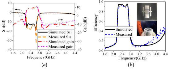
Figure 10. The filtering antenna design reproduced from [71]. 2020, IEEE: (
a
b
However, design complexity and system size are other challenges facing designers of filtering antenna structures. As explained in the literature, many design approaches have been carried out to offer a simple structure and compact size, which can be easily integrated with other RF front end systems. The multilayer structures presented in [
However, design complexity and system size are other challenges facing designers of filtering antenna structures. As explained in the literature, many design approaches have been carried out to offer a simple structure and compact size, which can be easily integrated with other RF front end systems. The multilayer structures presented in [,,,] have not managed these requirements. Moreover, substrate integrated waveguide (SIW) technology and the balun configuration were other notable attempts, as presented in [] and [], respectively. To summarize these approaches,Table 1 shows the performance comparison between the surveyed microstrip filter–antenna designs from the literature, which have similar performance. It should be noted that the filter–antenna design proposed in [
3 shows the performance comparison between the surveyed microstrip filter–antenna designs from the literature, which have similar performance. It should be noted that the filter–antenna design proposed in [] has a compact size with a simple structure and offers higher gain, higher selectivity, a wider fractional bandwidth, and good reflection coefficient characteristics. In summary, without a need for extra filtering circuits, the design presented in [] offers a new solution for current and future filtering antenna designs.Table 13.
[72][73][74][75][76][77][78][79][80][81][82][83][84][85][86]. In [79], a multiband tunable filter cascaded with a monopole antenna for cognitive radio communications is presented. The reconfigurable design covers four useful applications, including 1.9 GHz (GSM), 2.5 GHz (Bluetooth), 3.6 GHz (WiMAX), and 5.3 GHz (WLAN). Additionally, the deigned multiband filter–antenna provides a gain range from 1.2 dBi to 3.5 dBi in the four operating bands, with small variations of about 0.5 dBi between the adjacent bands, delivering a radiation efficiency above 60%.
Additionally, many reconfigurable microstrip filter–antenna structures have been presented and discussed [72,73,74,75,76,77,78,79,80,81,82,83,84,85,86]. In [79], a multiband tunable filter cascaded with a monopole antenna for cognitive radio communications is presented. The reconfigurable design covers four useful applications, including 1.9 GHz (GSM), 2.5 GHz (Bluetooth), 3.6 GHz (WiMAX), and 5.3 GHz (WLAN). Additionally, the deigned multiband filter–antenna provides a gain range from 1.2 dBi to 3.5 dBi in the four operating bands, with small variations of about 0.5 dBi between the adjacent bands, delivering a radiation efficiency above 60%.Table 2 compares some of the similar reconfigurable filtering antenna designs in the literature with the design presented in [79]. However, it is shown that the reconfigurable filtering antenna presented in [79] has a smaller size and wide tuning range, covering four discrete configurations for four important wireless applications.
4 compares some of the similar reconfigurable filtering antenna designs in the literature with the design presented in [79]. However, it is shown that the reconfigurable filtering antenna presented in [79] has a smaller size and wide tuning range, covering four discrete configurations for four important wireless applications.Table 24.
| Ref. | Year | Topology | Switches Number/Type | Size (mm) | Frequency Range (GHz) | Gain (dBi) | Advantages/Challenges/ Limitations |
||||||||||||
|---|---|---|---|---|---|---|---|---|---|---|---|---|---|---|---|---|---|---|---|
| [72] | 2012 | Hexagonal slot | 1/Varactor | 30 × 59 | 6.2–6.5 | 5.7–6.7 | Band-limited control | ||||||||||||
| [81] | 2015 | Ring slot | 0.7 × 0.3 × 0.1 | 1 PIN Diodes + 2 varactors | 3.7–4.7 | 3 | No | Wideband, tunable bandpass | [73] | 2016 | E-shaped patch | 2/PIN diodes | 36 × 14 | 2.1, 2.4 | - | Dual-band only | |||
| [82] | 2017 | Coupled lines | 0.4 × 0.2 × 0.01 | 2 PIN diodes | 3–4.5 | [74] | 2014 | Slot resonator | 2/PIN diodes | 103 × 120 | 1.6–6 | 2.3 | Large size | ||||||
| [59] | 2019 | Patch slot | 3.6 | 15 | 0.92 × 0.86 | > 14 | 10 | Metasurface | |||||||||||
| 3.6 | No | Wideband, tunable bandpass | [75] | 2017 | Open-loop resonator | 5/PIN diodes | 40 × 45 | 2.2–11 | 2.1–2.3 | Needs more diodes | [61] | 2016 | Quasi-Yagi | 2.5 | 22.8 | 1.7 × 1.3 | > 20 | 5 | balun |
| [77] | 2019 | 4 Distinct resonators | 4/PIN diodes | 30 × 60 | 1.8–5.2 | 1.1–3.4 | Compact, discrete tuning | [62] | 2014 | Ring slot | 2.5 | 15 | 0.76 × 0.76 | > 15 | 2 | Multilayer | |||
| [63] | 2011 | Quasi-elliptic | 5 | 2 | 0.90 × 0.90 | > 15 | 4 | None | |||||||||||
| [64] | 2017 | Open-loop | 2.45 | 6.4 | 0.72 × 0.70 | > 15 | 6 | None | |||||||||||
| [66] | 2011 | Coupled lines | 2.5 | 16.3 | 0.70 × 0.70 | > 20 | 2.4 | None | |||||||||||
| [67] | 2015 | Ring slot | 2.5 | 8 | 0.75 × 0.75 | > 14 | 4.5 | None | |||||||||||
| [71] | 2020 | Coupled lines | 2.4 | 20.1 | 0.60 × 0.60 | > 16 | 9.5 | None |
FBW: Fractional bandwidth; RL: Return loss; SIW: substrate integrated waveguide.
Additionally, many reconfigurable microstrip filter–antenna structures have been presented and discussed
A filter–antenna design with a reconfigurable frequency and bandwidth using an F-shaped feeding network is presented in [77]. The new feeding technique generates a multipath coupling scheme and provides the cross-coupling required to improve the out-of-band characteristics. Additionally, two varactor diodes are used and designed within the feeding network. The achieved performance shows that the proposed reconfigurable filter–antenna design has tunable frequency ranges from 2 GHz to 2.52 GHz, a fractional bandwidth that is tunable from 2.2% to 21.3%, a measured maximum gain of about 7.6 dBi, and a measured peak total efficiency of 85%.
A filter–antenna design with a reconfigurable frequency and bandwidth using an F-shaped feeding network is presented in [77]. The new feeding technique generates a multipath coupling scheme and provides the cross-coupling required to improve the out-of-band characteristics. Additionally, two varactor diodes are used and designed within the feeding network. The achieved performance shows that the proposed reconfigurable filter–antenna design has tunable frequency ranges from 2 GHz to 2.52 GHz, a fractional bandwidth that is tunable from 2.2% to 21.3%, a measured maximum gain of about 7.6 dBi, and a measured peak total efficiency of 85%.Figure 2 shows a photograph of the implemented reconfigurable filtering antenna design with simulated and measured reflection coefficients and boresight gain.
11 shows a photograph of the implemented reconfigurable filtering antenna design with simulated and measured reflection coefficients and boresight gain.Table 3 presents the performance comparisons between some recently published reconfigurable filtering antenna designs.
5 presents the performance comparisons between some recently published reconfigurable filtering antenna designs.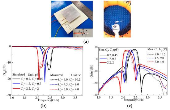
Figure 211. The reconfigurable filtering antenna reproduced from [77]. 2020, IEEE: (
a
b
c
| Ref. | Year | Topology | Size λ0 |
Number of Switches | Frequency Range (GHz) | Gain (dBi) | Pattern Reconfiguration (Challenges/ Limitations) |
Advantages |
|---|---|---|---|---|---|---|---|---|
| [ | ||||||||
| 83] | 2016 | S-shaped split-ring | 0.4 × 0.3 × 0.002 | 2 PIN diodes | 3.1–3.8 | 1–2 | No | Tunable bandpass, tunable bandstop |
| [84] | 2019 | Quasi-Yagi–Uda | 0.7 × 0.7 × 0.008 | 2 PIN Diodes + 4 varactors | 3.4–5.4 | 5–9 | No | Tunable bandpass, tunable bandstop |
| [85] | 2018 | Coupled lines | 1.2 × 1.2 × 0.17 | 4 PIN diodes | 1.7–3.7 | 8–10 | Yes | Wideband |
| [86] | 2019 | Coupled lines | 1.2 × 1.6 × 0.007 | 4 PIN diodes | 2.5–6.5 | 4.8 | Yes | Wideband, tunable bandpass, tunable bandstop |
It should be noted that considering both filter–antenna integration and reconfigurability properties at the same time will lead to some more advantages. However, this will also pose some challenges for both the biasing circuit and the structure configuration. In [48], two PIN diodes and four varactors are utilized in the basing circuit. Despite this configuration adding more complexity to the structure, it also results in a compact size and good performance in terms of the tuning range and the realized gain. It is also shown that wideband and tunable bandpass performance can be achieved by using the filter antenna integration design presented in [86]. This configuration has a high degree of freedom in terms of controlling the S-parameter characteristics and the radiation pattern behavior using a compact size structure. Thus, this makes the designed reconfigurable filter antenna a good candidate for current and future wireless applications
It should be noted that considering both filter–antenna integration and reconfigurability properties at the same time will lead to some more advantages. However, this will also pose some challenges for both the biasing circuit and the structure configuration. In [48], two PIN diodes and four varactors are utilized in the basing circuit. Despite this configuration adding more complexity to the structure, it also results in a compact size and good performance in terms of the tuning range and the realized gain. It is also shown that wideband and tunable bandpass performance can be achieved by using the filter antenna integration design presented in [86]. This configuration has a high degree of freedom in terms of controlling the S-parameter characteristics and the radiation pattern behavior using a compact size structure. Thus, this makes the designed reconfigurable filter antenna a good candidate for current and future wireless applications3. Comparison between Switching Techniques
The common types of reconfiguration techniques that can be utilized to implement reconfigurable structures are illustrated in
Table 4 [87][88][89][90][91][92][93][94][95][96]. Structures based on RF-MEMS [88], PIN diodes [89], and varactors [90] that redirect their surface currents are called “electrically reconfigurable.” RF structures that use photoconductive configuration switch components are called “optically reconfigurable” [92]. Electronically reconfigurable or tunable elements are the best option when size and efficiency are required. However, the power handling capability and the lifetimes of these reconfiguration techniques cause some essential issues. PIN diodes operate in two configurations. The “on” state is where the diode is forward biased and the “off” state is where the diode is not biased or reverse-biased, while RF-MEMS uses mechanical movement to obtain a short circuit or an open circuit in the surface current path of RF elements. Unlike PIN diodes and RF MEMS, varactors can provide a continuous tuning range, with typical capacitance values range from tens to hundreds of picofarads. Moreover, unlike electrical reconfiguration, the photoconductive technique does not require the use of bias circuits and can be loaded in the RF PCB board without adding a complex design to modify the radiating elements. Additionally, the activation–deactivation mechanism for the switch does not create harmonic issues or intermodulation distortion. Conversely, in contrast with active switches, the optical switches are less common because of lossy characteristics and the need for complex activation approaches [96]. A description of the operation of the switches and comparisons between them are summarized in
| Properties | PIN Diode | Varactor | RF MEMS | Photoconductive |
|---|---|---|---|---|
| Speed (µsec) | 1–100 × 10−6 | 0.1 | 1–200 | 3–9 |
| Quality factor | 50–85 | 25–55 | 86–165 | - |
| Voltage (V) | 3–5 | 0.1–15 | 20–100 | 1.8–1.9 |
| Current (mA) | 3–20 | 1–25 | 0 | 0–87 |
| Power (mW) | 5–100 | 10–200 | 0.05-0.1 | 0–50 |
| Temperature sensitivity | Medium | High | Low | Low |
| Cost | Low | Low | Medium | High |
| Loss at 1 GHz (dB) | 0.3–1.2 | 0.5–3 | 0.05–0.2 | 0.5–1.5 |
| Fabrication complexity | Commercially available | Commercially available | Low fabrication complexity | Complex |
4. Current Challenges and Future Developments
Over the last few years, RF designers, researchers, and engineers have made a huge effort to explore reconfigurable filters and antennas and their integration as alternatives to the existing approaches and topologies, along with developing high-RF front end performance. Compared to the classical and passive filters and antennas, some essential challenges accompany the integrated and reconfigurable filters and antennas, which are efficient, compact, and multifunctional. Although recent researches show that microstrip planar configurations are capable of reducing the structure size, having the ability to produce a wider and flexible tuning range with low power and low loss is currently an important issue. As can be observed from the previous sections of this review, filter–antenna integration with reconfigurable characteristics requires a complex configuration, which can be considered as a common challenge for all reconfigurable transceivers. To overcome this challenge, some reconfigurable or tunable planar filters employing dual-mode ring resonators were introduced in [29][32][35]. Furthermore, the reconfigurable filter introduced in [36] has excellent performance in terms of the S-parameter group delay and S
21
Additionally, the realization of reconfiguration approaches in RF and MW components improves the multifunctional performance of the entire system. In the literature, several studies have stated the importance of reconfiguration techniques. For instance, an E-shaped microstrip wideband antenna with polarization diversity was presented in [97] to work in the frequency range of 2.3 GHz to 2.6 GHz. In a similar way, radiation pattern reconfigurable wideband microstrip antennas are also introduced in [98][99] to operate in the spectrum ranges of 2.3 GHz to 2.55 GHz and 1.6 GHz to 4 GHz, respectively. As shown in these papers, the integration of slots, lumped elements, and surface mount components in the radiating patch penetrates the radiation pattern performance. To overcome these problems, several papers in the literature utilize the feed line of the antenna to achieve filtering performance with reconfigurable characteristics. Some of the recent research studies in the literature that apply this technique to obtain filtering performance include [61][62][63][64]. Additionally, a filter–antenna design with a reconfigurable frequency and bandwidth using an F-shaped feeding network was presented in [100]. This technique generates a multipath coupling scheme and provides the cross-coupling required to improve the out-of-band characteristics.
Additionally, wideband filtering antenna designs are essential components of future wireless applications used to tackle high-speed and high data rate transmissions. For these designs, it is noticed that the size, insertion loss, and differential-mode bandwidth should also be taken into consideration and carefully investigated by the designers. Most of the introduced wideband and ultra-wideband filtering antenna configurations are designed based on a single-layer substrate. Therefore, it should be pointed out that using liquid crystal resonators and low-temperature co-fired ceramics can enhance the out-of-band rejection, thus improving and enhancing the performance of the wideband communication systems [101][102][103].
Reconfigurable filtering antennas based on substrate-integrated waveguide (SIW) technology can also be used for mmWave and 5G wireless communications to provide lower losses, higher quality factors, and more power handling capability when compared with the other surveyed approaches [104]
. Additionally, using these techniques offers some advantages, such as enhancing the bandwidth and reducing the losses and sizes of the configurations. According to what is shown in this review, the design technique proposed in [86] can also overcome the challenges facing these technologies by using only one single-layer, half-mode, substrate-integrated waveguide resonator loaded with four slot lines. Furthermore, and with as any RF or microwave element, reconfigurable filters and antennas and systems combining both of these can also be designed, analyzed, and optimized using artificial intelligence, neural networks, and bio-inspired optimization algorithms [105][106][107][108]. These approaches can be utilized for future reconfigurable structures, since these designs require more analysis and parameter studies than classical and passive configuration. Therefore, using these approaches in the future could lead to overcoming several issues and challenges by processing many variables at one time. It is anticipated that new design techniques with high efficiency and fully reconfigurable characteristics will be seen shortly.