Innovative renewable routes are potentially able to sustain the transition to a decarbonized energy economy. Green synthetic fuels, including hydrogen and natural gas, are considered viable alternatives to fossil fuels. Indeed, they play a fundamental role in those sectors that are difficult to electrify (e.g., road mobility or high-heat industrial processes), are capable of mitigating problems related to flexibility and instantaneous balance of the electric grid, are suitable for large-size and long-term storage and can be transported through the gas network.
- green synthetic fuels
- power-to-gas
- technology readiness level
- supply chain
- gas quality
Note: The entry will be online only after author check and submit it.
1. Introduction
2. Heat-to-Gas Routes
The conversion of solar radiation realizes thermochemical solar fuels via concentrated solar power (CSP) technologies into heat that is needed to carry out high temperature reactions. The main thermochemical processes that exploit only renewable and abundant resources without GHG emissions are water thermolysis and thermochemical cycles that need only water, carbon dioxide and concentrated solar power. Other thermochemical routes for solar power production (steam reforming, cracking and gasification) require fossil fuels as raw materials [67]. In this review, only the two emission-free processes are analyzed.
2.1. Solar Water Thermolysis
Solar water thermolysis consists of a single-step direct thermal decomposition of water molecules into hydrogen and oxygen carried out by the exploitation of concentrated solar power. The chemical bond between oxygen and hydrogen requires high bond-dissociation energy. Therefore, the reaction is enhanced by high temperature above 2500 K to obtain a suitable product yield (at 1 bar and 2500 K the dissociation efficiency is approximately 10%) [68]. Solar radiation is first collected and concentrated using a concentrated solar power collector. The required concentration ratio of CSP is of the order of 10,000, and the incident solar energy required is of the order of 10 MW (reached with parabolic dish concentrator, double-concentration systems or solar tower with a heliostat field) [69]. The thermolysis reactor is a refractory nozzle in which the liquid water flows continuously and is vaporized and dissociated. The high temperature needed for the reaction requires the use of special materials such as oxide ceramics including yttria, zirconia and magnesia [70]. The dissociation is partial, and the output depends on temperature and pressure. The process can be summarized by the overall endothermic reaction [71]:
H2 O ↔x1H2 O+ x2OH+x3O+x4H+x5H2+x6O2(1)
The methods used for the energy transfer to water molecules are: (i) bulk heating of water vapor in a furnace cavity with a fluid tubular wall; (ii) direct contact of cold vapor with a hot solid layer covering the walls of the cavity reactor; and (iii) direct contact of liquid water with the hot solid plate [72].
The separation of the resulting gas mixture constitutes a critical issue due to the risk during slow cooling of recombination of hydrogen and oxygen that could lead to an explosive mixture. Indeed, the lower limit of flammability of a mixture of oxygen and hydrogen is approximately 5%. The separation is realized via two main processes: at the reaction temperature or after a rapid quenching.
The product separation at the gas temperature is carried out by the continuous removal of one of the reaction products enhancing the thermolysis reaction and preventing the recombination. The separation is obtained via a variety of methods [71,72]:
- Microporous ceramic membranes made of refractory materials in sub-atmospheric pressure reactors that allow selective separation of a species [73].
- Membranes semipermeable to oxygen made by a high temperature solid electrolyte material (ZrO2, CaO, CeO2, Y2O3, perovskite) placed in a chemical potential gradient. The mixed ionic and electronic conducting (MIEC) membranes are realized with refractory oxides with a mixed type of electrical conductivity with ionic and electronic components. In the presence of a gradient of oxygen pressure, a chemical potential induces migration of oxygen ions across the membrane, and an electron current circulates in the opposite direction due to electronic conductivity of the material [74].
- Metallic membranes made of palladium and its alloys. Hydrogen is dissociated on the nonporous metallic membrane surface, and its atoms diffuse through the membrane and are desorbed and recombined after the membrane [20,75].
- A rotating cylindrical vessel in which the gas mixture could pass through. The centrifugal field of force modifies the equilibrium pressure of species, separating them [76].
- Supersonic jets generated by expanding a gas mixture rich of dense gases near the jet axis and with lighter gases on the external part. This distribution leads to beam deflection and gas separation due to centrifuge forces in the curved flow [77].
The diffusion flow increases with high temperature and a high-pressure gradient.
The product gas separation via rapid quenching is realized by cooling the product gas at a cooling rate of 105–106 K/s by the direct contact with a cold auxiliary fluid. The quenching is a highly irreversible process, and it permits to recover hydrogen up to 90%. The temperature of the cold, inert fluid is 450–500 K, since the temperature should decrease by 1500–2000 K in a few milliseconds [78]. The cooling rate must be faster than the rate of heat released by the recombination reaction. The quenching process is realized either in an external vessel or internally in the reactor (auto-quenching). The hot gas is cooled down by heat exchange cooling, auto-cooling by the jet of cold stream, auto-cooling by direct contact with cold water or by rapid turbulent cold gas jets [79].
2.2. Thermochemical Cycles
Thermochemical cycles are a suitable process for the production of both syngas and hydrogen. Water splitting via thermochemical cycles addresses problems related to the separation of product gases since the production of hydrogen and oxygen occurs in different steps. The operating temperature needed is relatively low (1100–1500 K) [80]. If only water constitutes the inlet fluid, the product gas is hydrogen, whereas if a mixture of water and carbon dioxide is introduced in the reactor, syngas is generated. Therefore, water, carbon dioxide and heat are the input and oxygen, carbon monoxide and hydrogen the only output. The other reagents are regenerated in a closed loop. The production of pure hydrogen without contaminants allows the direct utilization in fuel cells. Cycles are generally composed of two or three steps and involve metal oxide redox reactions. Two-step thermochemical cycles require high temperature, but also the efficiency of the overall reaction is high. The difference of temperature of oxidation and reduction reactions is the thermodynamic driving force for two-step thermochemical water splitting.
In the first step, the metal oxide (MOox) is thermally dissociated to the metal form or the lower-valence metal oxide (MOred), and oxygen is released (see Figure 1). The reaction is highly endothermic and requires high temperatures [67].
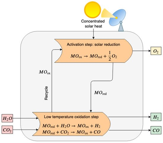
Figure 1. Scheme of a two-step thermochemical cycle for H2O and CO2 splitting using metal oxide in a redox system. In the activation step, the metal oxide (MOox) is thermally decomposed via an endothermic reaction that requires high-temperature heat provided by concentrated solar power (CSP). In the oxidation step, the reduced metal oxide (MOred) reacts with steam and carbon dioxide producing syngas (H2 and CO). Finally, MOox is recycled.
High-temperature reduction (activation step):
MOox→MOred+12 O2(2)
In the second exothermal step, the hydrolysis of the reduced metal oxide and water splitting occurs. Pure hydrogen and the primary metal oxide are produced. The pure metal oxide is recycled back to the solar reduction reactor, closing the material cycle.
Low-temperature oxidation with H2O (H2 generation step):
MOred+ H2O→MOox+H2(3)
Similarly, syngas could be obtained by introducing a mixture of CO2 and H2O in the reactor vessel. CO2/H2O thermochemical cycles are a possible route for the utilization of the carbon dioxide captured from other processes.
Low-temperature oxidation with CO2 (CO generation step)
MOred+CO2→MOox+CO(4)
The previous reactions may be classified as oxide type and are the most investigate nowadays, but other two types of reaction are developed: the hydride type and the hydroxide type [81].
Hydride type: MH2→ M+H2(5)
M+H2O→MH2+12 O2(6)
Hydroxide type: 2MOH→2M+H2O+12 O2(7)
2M+2H2O→2MOH+H2(8)
Many thermochemical cycles with metal oxide redox couple have been proposed [82], including Fe3O4/FeO [83,84,85,86], TiO2/TiOx [87], Mn3O4/MnO [88], Co3O4/CoO [89,90], ZnO/Zn [86,91,92], SnO2/SnO [93,94,95], CeO2/Ce2O3 [96,97], CdO/Cd [98,99] and W/WO3 [100]. The most investigated materials are zinc, iron and ceria metal oxides. Nakamura [101], in 1977, first proposed a two-step thermochemical cycle based on Fe3O4/FeO. Iron oxide has a great reduction capacity that enhances the product yield, but the high volatility of ferrite oxides reduces the lifetime of the material and increase operational cost. Ceria is more stable than ferrite but requires a higher temperature in the activation step [102]. Zinc is probably the most promising metal oxide redox pair for its high energy efficiency (44% with heat recovery from the quenching process and 29% without the heat recovery) [86,91]. The use of mixed metal oxides could decrease the reduction temperature required and increase the melting point. Mixed metal oxides are generated by the partial substitution of the primary materials with dopants including Mn, Co, Ni, YSZ and Zn for ferrite cycles [103,104,105,106,107,108], and Zr, Hf, La, Pr, Sm, Gd and Tb for ceria cycles [109,110,111,112,113]. The theoretical energy conversion efficiency of the iron oxide cycle is 39% and up to 75% by recuperating the high-temperature heat and 28% for un-doped ceria without heat recovery [114,115].
Some of the redox pairs, when reduced, mutate to the gaseous phase (for example, the reduction of ZnO and In2O3 to gaseous Zn and In2O, respectively) [80,81]. Volatile cycles are thermodynamically more advantageous, since the formation of the vapor product ensures a higher entropic gain. However, a quenching reactor is needed after the activation step to avoid possible recombination with oxygen and to recover the reduced metal oxide in the condensate phase [116,117]. Non-volatile cycles allow the continuous removal of oxygen from the solid metal oxide, avoiding the recombination and quenching problems.
Three-step thermochemical water splitting is similar to two-step thermochemical cycles, but the former generally requires a lower maximum temperature. However, three-step cycles involve a higher complexity of the plant. Reactions involved in a three-step metal oxide cycle are:
MOox→MOred+12 O2(9)
MOred+2M′OH→ M′2O⋅MOox+H2(10)
M′2O⋅MOox+H2O→MOox+2M′OH(11)
In the first step, the metal oxide (MOox) is thermally decomposed to the metal form or the lower-valence metal oxide (MOred), and oxygen is released. In the second step, the reduced metal oxide (MOred) reacts with an alkali metal hydroxide (2M’OH) generating a mixed oxide (M’2O•MOox) and hydrogen. In the third reaction, the mixed oxide is hydrolyzed by the steam regenerating the metal oxide and the alkali metal hydroxide [118]. Sulfur–iodine (S–I), copper–chlorine (Cu–Cl) and magnesium–chlorine (Mg–Cl) are the most promising and investigated three-step thermochemical cycles.
In Figure 2 a schematic diagram of the sulfur–iodine thermochemical cycle is proposed. The maximum temperature required is 1100–1200 K in the first endothermic chemical reaction in which the sulfuric acid (H2SO4) is decomposed into steam, sulfur dioxide (SO2) and oxygen. In the second step, the Bunsen reaction occurs at 300–400 K. Iodine and water enter the reactor and promote the formation of sulfuric acid and hydroiodic acid (HI) reacting with sulfur dioxide. Finally, in the third step, the hydronic acid is split in iodine and hydrogen at 600–800 K [119]. Some drawbacks are the corrosive nature of the species and the poisoning of the aqueous acid phases (HI and H2SO4) that requires additional energy-expensive treatments to separate these compounds. Caple et al. [120] propose an experimental feasibility analysis of a novel sulfur-sulfur cycle that abolish the need for the processing of hydroiodic acid. Yilmaz et al. [121] evaluate the exergy and energy efficiency of the S–I thermochemical cycles by varying several parameters, including operational conditions, state properties and reference environment. The computed thermochemical cycle energy efficiency is 43.85%, and the efficiency of the whole system is 32.76%. The exergy efficiency is 62.39% and 34.56% for the cycle and the whole system, respectively.
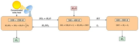
Figure 2. Scheme of a sulfur–iodine three-step thermochemical water splitting. In the first endothermic step, H2SO4 is decomposed into steam, SO2 and oxygen that is released. Steam and SO2 react in the second reactor with I2, resulting in the formation of H2SO4 that is recirculated to the first-step reactor and HI that enters the third-step reactor. In the third reactor, HI is split into I2 and H2. I2 is recirculated to the second-step reactor and H2 is released.
The copper–chlorine thermochemical water splitting requires a maximum temperature slightly lower than S–I cycles. Low temperature allows the coupling with various heat sources (mainly nuclear reactors) [122]. Moreover, in Cu–Cl cycles, fewer challenges of equipment material and product separation occur, but the higher price of electricity than heat reduces these advantages from an economic viewpoint [123]. The oxygen production occurs at approximately 800 K, and it represents the maximum temperature needed. However, Cu–Cl cycles also involve electrical energy for the electrolysis step in which hydrogen is produced [124]. In the electrolysis step copper(I) chloride (CuCl) reacts in an aqueous solution with hydrochloric acid (HCl) giving rise to copper(II) chloride (CuCl2) and H2. After drying, CuCl2•H2O is hydrolyzed and forms the solid-phase melanothallite (CuOCuCl2) and HCl. Finally, CuOCuCl2 generates the molten salt CuCl and oxygen through an endothermic reaction [124,125]. Balta et al. [126] propose an energetic and exergetic analysis of a Cu–Cl thermochemical cycle coupled with a geothermal source for hydrogen production via a parametric study. The overall energy efficiency obtained is 21.67%, and the exergy efficiency is 19.35%.
Magnesium–chlorine thermochemical cycles have been developed as an alternative to the single-step reverse Deacon reaction in a two-step chemical loop by Simpson et al. [127]. Three-step hydrogen production is a hybrid thermochemical-electrolytic process, such as Cu–Cl cycles. It involves two thermochemical reactions that require a maximum temperature of 700–800 K and one electrolytic process. In the first step, the magnesium dichloride (MgCl2) reacts with steam and is split in magnesium oxide (MgO) and HCl. The second step involves the reaction between MgO and chlorine (Cl2), generating O2 and MgCl2. The last step concerns the electrolysis of anhydrous HCl into H2 and Cl2 [128,129]. Balta et al. [130] perform the parametric study of energy and exergy efficiency also for this process. The overall energy efficiency obtained is 63.63%, and the exergy efficiency is 34.86%.
2.2.1. Reactors
The solar reactor is the item that receives and transforms the solar radiation into thermal energy.
The reactor has to endure high temperature and high heating rate, promote the heat transfer and reduce energy losses. The requirement of high temperatures is a critical issue of thermochemical water splitting due to the risk of the thermal shock of reactor walls. Further, the reactivity and corrosivity of some reactants (e.g., sulfur and iodine) and the strong oxidizing environment necessitate materials resistant to corrosion. Possible solutions are the use of compatible materials (e.g., ZrO2, graphite or silicon carbide) and the design of reactors to prevent direct contact between chemicals and wall materials [115].
In 1995, Tamaura et al. [131] proposed a first two-step water-splitting cycle, demonstrated experimentally in the solar furnace of the Paul Scherrer Institute, with a two-stage concentrator system and a tubular packed-bed reactor of quartz.
Gokon et al. [132] propose and demonstrate on a laboratory-scale prototype reactor a thermochemical two-step water-splitting cycle using an internally circulating fluidized bed reactor with a redox system of iron-based oxides and ferrite. The cylindrical reactor was made of stainless steel with a beam-down transparent optics. The beam-down optics is a quartz window installed in the ceiling of the reactor to prevent contact between particles and the transparent window. Particles are transported upwards in a draft tube where are directly heated by concentrated solar radiation and move downward in the annulus region. The particles circulation guarantees solar energy transfer from the top to the bottom. The circulating fluidized bed reactor provides a more uniform temperature distribution compared to a packed-bed reactor.
The German Aerospace Center (DLR) develops in the past years fixed coated ceramics reactors as a promising alternative to packed-bed reactors within the project HYDROSOL (HYDROgen production in a SOLar monolithic reactor) [133]. Reactors are realized by a ceramic multi-channeled monolithic honeycomb structure; within are incorporated active iron-oxide-based redox pairs. Walls are coated with silicon carbide (SiC) that ensures high thermal shock resistance, high mechanical strength and high thermal conductivity allowing the operational temperature of approximately 1073–1473 K. The whole plant was tested at the laboratory scale in the solar furnace at DLR, in Cologne.
Fluid-wall reactor configuration appears as a promising technology to control high temperature and corrosivity of thermochemical cycles. The heating rate is very high (up to 105 K/s), and the graphite structure allows ultra-high operational temperatures. The graphite solar-powered fluid-wall aerosol flow reactor has been studied principally for the decarbonization of methane [134]. The reactor is realized with three concentric vertical tubes: the inner tube (“reaction tube”) is made of porous graphite; the central tube (“heating tube”) is composed of solid graphite; the outer tube (“protection tube”) is made of quartz. The concentrated solar power enters through the outer tube that is either totally or partially transparent and heats directly the center solid graphite tube that radiates to the inner porous graphite tube. A non-oxidizing atmosphere is guaranteed by feeding an inert or compatible gas such as argon, helium, neon or nitrogen that flows radially through the porous graphite tube to prevent contact and reactions between graphite and process chemicals (reactants and products). The realization of the protection tube with a quartz window instead of the totally transparent tube provides a reflective inner surface that increases the thermal efficiency [135].
Tapia et al. [136] propose a thermal design and experimental test for a multi-tubular solar reactor (see Figure 3d). The solar radiation enters inside the semi-cylindrical cavity and is absorbed by the alumina tubes in which the ferrite pellets involved in the thermochemical cycle are placed. Furler and Steinfeld [137] propose a dynamic numerical model and test a cavity receiver with a circular quartz window containing a cylinder of reticulated porous ceramic foam made of ceria to develop novel reactor design and configuration to improve energy-to-fuel conversion efficiency.
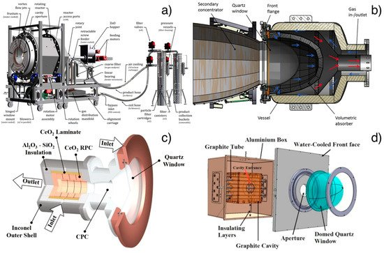
Figure 3. (a) Rotary cavity receiver of the demonstration plant for ZnO dissociation at PROMES-CNRS (PROcédés, Matériaux et Énergie Solaire-National Centre for Scientific Research) furnace. Reprinted with permission from [145]; (b) Monolithic reactor with a foam structure (HYDROSOL-HYDROgen production in a SOLar monolithic reactor-project). Reprinted with permission from [148]; (c) cavity receiver containing a reticulated porous ceramic foam made of ceria (ETH furnace). Reprinted with permission from [137]; (d) multi-tubular solar thermochemical reactor in a 50 kWth plant for methane dissociation. Reprinted with permission from [150].
Also, rotary-type solar reactors have been researched and tested for water-splitting thermochemical cycles. Kaneko et al. [138] manufacture a solar reactor with a beam-down quartz optics that has a cylindrical rotor and dual cells for discharging O2 and for splitting H2O. The rotor is coated with reactive ceramics (CeO2 and Ni, Mn-ferrite). By the rotational movement of the rotor, each fraction of the reactive ceramics is reduced in the O2 releasing cell and split water in the other cell by the rotation. Argon gas is injected to both cells to carry out the gaseous products.
Schunk et al. [139] propose and test reactor prototypes that consist of a multilayer cylindrical rotary cavity receiver made of ZnO tiles placed on a ceramic structure and ZnO particles. The rotation of the rotor forces the oxide particles to the edge of the reactor where they are exposed to solar irradiation. ZnO operates as a radiant absorber, a chemical reactant and a thermal insulator and argon gas is added to protect the quartz window from condensed zinc. Diver et al. [140] propose a two-step solar-driven thermochemical reactor based on iron and ferrite oxide. The reactor is realized with a stack of several counter-rotating rings with fins that contain reactive metal oxide. During the reactor rotation, the reactive material pass through the irradiated zone where is reduced. On the opposite side, water splitting occurs. The oxidized ferrite materials enter into the recuperation zone in which they heat up while the neighboring fins move in the opposite direction cool down.
Finally, the Center for Research and Technology Hellas in Thessaloniki proposes a perovskite redox membrane reactor for the isothermal and continuous production of high purity hydrogen. The reactor consists of two compartments separated by the membrane. Water vapor is introduced in the oxidizing side and is split, producing hydrogen and oxygen. Oxygen ions diffuse in the membrane lattice and are desorbed in the opposite membrane side. To enhance the desorption process, an oxidable agent could be introduced [141].
2.2.2. Technology Readiness Level
Water direct thermolysis and thermochemical cycles are researched mostly at the laboratory scale, but only a few processes have been tested in all steps, with integrated experimental demonstration cycle closure. Direct thermolysis is unlikely in the near term due to the high temperature requirement and the need to separate products after the reaction process [115]. However, recently, several pilot and demonstration plants concerning two-step and three-step thermochemical cycles have been developed worldwide.
A 4 kWth solar reactor prototype (TRL 4–5) has been tested at ETH’s high-flux solar simulator facilities to experimentally validate the numerical model proposed by Furler and Steinfeld for the heat and mass transfer computational simulation of a cavity receiver containing a reticulated porous ceramic foam made of ceria (see Figure 4c) [137].
The international collaboration of Japan and Australia in Asia-Pacific Partnership on Clean Development and Climate (APP) project have carried out a test operation of the Tokyo Tech solar rotary-reactor using the solar concentration technology of National Solar Energy Centre at Commonwealth Scientific and Industrial Research Organization (CSIRO). The power input is 50 kWth from the solar concentrator system with 10 heliostats and two-step water-splitting thermochemical cycle with reactive ceramics of ceria-based solid solution is performed in a beam-down rotary-reactor [142].
In the framework of the SolH2 project (an INNPACTO initiative of the Spanish Ministry of Economy and Competitiveness), a 100 kWth multi-tubular reactor proposed by Tapia et al. [136] has been built and tested in the SSPS-CRS facility of the Plataforma Solar de Almería (PSA) to demonstrate the technological feasibility of solar ferrite thermochemical water-splitting cycles [143].
A demonstration plant with a thermal input of 100 kWth for the water thermal dissociation based on ZnO was designed and tested at the large-scale solar concentrating facility of PROMES-CNRS (PROcédés, Matériaux et Énergie Solaire-National Centre for Scientific Research) MegaWatt Solar Furnace (see Figure 4a) [144,145]. This project followed the previous 10 kWth pilot plant of a rotary cavity receiver experimentally demonstrated at PSI’s High-Flux Solar Simulator by Schunk et al. [139].
Within the EU-funded project, the HYDROSOL Plant has been developed and implemented an industrial-scale plant of a two-step thermochemical cycle with a temperature up to 1400 °C. A plant on a solar tower of the PSA has been built with monolithic reactors based on the fixed coated ceramics reactor proposed by DLR researchers [133]. A plant with a thermal input of 100 kWth (HYDROSOL and HYDROSOL-II) and with two ceramic multi-channeled monolithic honeycomb reactors coated with nickel-ferrite reactive species was previously realized [146,147]. In 2016, this plant was scaled-up to 750 kWth (HYDROSOL-3D) using three monolithic reactors with a foam structure wholly made of nickel-ferrite powders to overcome the problem with the coating of ceramic (see Figure 4b) [148].
For the commercialization of water-splitting thermochemical reactors, further research is needed to develop competitive thermochemical plants. The research should focus on reactor materials resistant to high temperature, thermal shock and chemical corrosion, on quenching processes of products and on the separation of reactants (e.g., in S–I cycles). Moreover, further development of solar concentration technologies is needed to enhance the total conversion efficiency that ranges between 35% and 50% and to reduce concentrator cost that contributes to approximately a half of the total capital cost of the plant [92,149].