Your browser does not fully support modern features. Please upgrade for a smoother experience.
Please note this is a comparison between Version 1 by Barbara Klemczak and Version 3 by Bruce Ren.
A rising demand for efficient functional materials brings forth research challenges regarding improvements in existing materials. Carbon infused cementitious composites, regardless of being an important research topic worldwide, still present many questions concerning their functionality and properties.
- cementitious composites
- cement nanocomposites
- carbon nanomaterials
- carbon nanotubes
- graphene
- smart materials
- structural health monitoring
Note: The entry will be online only after author check and submit it.
1. Introduction
The term ‘nanotechnology’ was first defined by professor Norio Toguchi in 1974. Defining the process of modifying material on an atomic level. It had continued an idea put forward by American physicist Richard Feynman, who said in 1959: “There’s plenty of room at the bottom”. With time, a basic definition of nanotechnology has evolved to be finally determined as: “the application of scientific knowledge to manipulate, control, and restructure matter at the atomic and molecular level in the range of 1–100 nm to exploit size-dependent and structure-dependent properties and phenomena distinct from those at different scales” [1].
Main opportunities for the use of nanotechnology were at first seen in the fields of electrical engineering and biotechnology. Since the beginning of the XXI century, nanotechnology also attracts researchers associated with civil engineering, and the founding of the research in this area is still rising [2]. The main scope of research in the case of cementitious nanocomposites is creating materials with enhanced mechanical properties as well as added functionality. Resistance to ageing and environmental aggression; capability of auto-monitoring or auto-repair; and energy saving through energy harvesting are important factors to consider regarding more resilient structures and concepts of smart cities. Moreover, resilient materials can effectively reduce the amount of maintenance needed while sensors inbuilt in building structures will allow for safer exploitation and early detection of problems. These materials are often called ‘smart materials’, as they possess properties that are not observed in a usual form of such material. Most often, the smartness of the material is connected with abovementioned functionality. For example, the ability to self-sense damage and strains is compared to a living organism’s neural system. Such form of biomimetic behavior is one of the most popular and most researched properties for a variety of smart materials.
Materials based on Portland cement are still the most popular type of materials used in civil engineering structures. Possessing high compressive and dynamic resistance, they are still prone to cracking and are generally brittle materials. Cracks caused by either mechanical or non-mechanical factors might often lead to degradation of materials, reduce their tightness, and allow for infiltration of aggressive substances. Fiber-reinforced concretes seem to counteract the problem of cracking; however, they are not able to bridge cracks at the nanoscale where they originate from. The addition of nanomaterials to concrete allows for strengthening at the molecular scale, bridging those small-scale cracks and densifying the material’s nanostructure. Moreover, nanoparticles allow for accelerated growth of stronger C-S-H phase crystals, increasing the material’s strength also in the matrix.
First known applications of nanoparticles in concrete used mostly titanium, silica, and aluminium oxides. Those additions have been proven to increase concrete’s extreme temperature resistance and intensify the hydration process [3][4][5][6][7][3,4,5,6,7]. Further usage of various types of carbon nanomaterials came mainly from the desire to add functionality to the composites. The idea of smart material sensors and heat transferring materials emerged, with the former being already used in aircraft engineering and epoxy composites.
-
Zero-dimensional materials (0D)—singular nanoparticles that mainly influence properties of the cementitious matrix itself,
-
One-dimensional materials (1D)—elongated structures (nanotubes, nanofibers), with one dimension much bigger than the other two that can bridge cracks,
-
Two-dimensional materials (2D)—platelets, for example, graphene, which two dimensions are much bigger than the third one, with a large surface area and ability to bridge cracks.
2. Carbon Nanomaterials
Carbon-based nanomaterials are atomic structures built from amorphous types of carbon, mainly fullerenes and graphite. They are composed of crystalline structures with strong bonds between carbon atoms. Depending on the arrangement and combination of those structures, they can form one- or two-dimensional formations. In general, carbon nanomaterials can come in each of the dimensional forms mentioned in the previous section.
2.1. Graphene
Graphene, a two-dimensional material, is mainly used in the form of sheets or graphene oxide (GO). First records describing graphene came from 1917, when it was described in oxide form [9]. Not until 2004, did Novoselov and Geim manage to obtain graphene in its raw form of platelets, using mechanical exfoliation of graphite [10]. Since then, more methods of producing graphene have been designed, allowing for more efficient production with consistent properties of the final product. One of the novel methods is Flash Joule Heating (FJL) method developed by Luong et al. [11]. Graphene obtained through this method is called ‘flash graphene’ and is made by converting amorphous carbon using high voltage electric discharge to heat carbon powder up to 3000 K. The whole process takes place in a quartz tube, under atmospheric pressure or mild vacuum. Another method, with a possibility for industrial usage, is electrochemical exfoliation used by Krystek et al. [12]. Their method of electrochemical exfoliation of graphene allows for a higher production rate of ~200 mg of electrochemically exfoliated graphene per 180 min of the electrolysis process, compared to ~10 mg per 10 min for the classical electrochemical exfoliation process. Exfoliation of graphene, both mechanical with the usage of ultrasonication or electrochemical, is a process of peeling singular flakes out of a graphite block in a liquid solution. Addition of solvent prevents peeled flakes from accumulating.
In its pure version, graphene appears as a 2D plane of carbon atoms arranged in a honeycomb shape. However, more functionalized versions have been developed. Graphene oxide (GO) is a more reactive derivative with multiple oxygen-containing functional groups. In terms of cementitious composites, those groups allow for easier dispersion in water however increase in conductivity of the composite is lower than for pure graphene [13]. Reduced graphene oxide (rGO) consists of fewer functional groups and is considered to be a middle ground between graphene and GO in terms of its properties [14]. The final group of graphene materials is graphene nano platelets (GNP), consisting of few stacked layers of graphene. The schematic representation of mentioned types of graphene is shown in Figure 1.
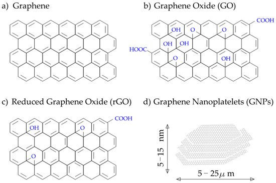
Figure 1. Representation of different forms of graphene materials: (a) pure graphene; (b) graphene oxide GO; (c) reduced graphene oxide rGO; (d) graphene nanoplatelets [14].
The excellent properties of graphene determine its position as one of the most promising and widely researched carbon nanomaterials. Its high thermal conductivity of ~5000 W/mK [15] and electron mobility of up to 200,000 cm2 V−1 s−1 [16] allow for its usage in self-sensing and energy-saving materials. At the same time, extraordinary mechanical properties: tensile strength of 130 GPa and Young modulus of 1 TPa [17], make graphene a viable material to be used as a reinforcing phase in composite materials.
2.2. Carbon Nanotubes (CNT)
Carbon nanotubes, first described by Sumio Iijima in 1991 [18], are classified as one-dimensional nanomaterial. Nanotubes consist of seamless, rolled graphene platelets, closed at the tip with half of the fullerene and are usually classified into one of the two groups: single-walled carbon nanotubes (SWCNT) or multi-walled carbon nanotubes (MWCNT) (Figure 2). The diameter of SWCNTs is between 1–2 nm, while for MWCNTs, which are stacked SWCNTs, 2–100 nm [19].
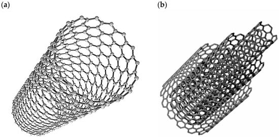
Figure 2. Schematic of carbon nanotubes structure: (a) single-walled nanotube; (b) multiwall nanotube [20].
One of the main techniques used in the production of CNTs is chemical vapor deposition (CVD) which employs catalytical conversion of carbon materials. The carbon material is dissolved into individual atoms during the process and then rearranged to regrow in an elongated form. CNTs grow atom by atom into a tubular shape with the help of a metallic catalyst. CVD method is considered to be the most effective method of producing CNTs on an industrial scale and with sufficient stability of their properties [21].
Similar to graphene, CNTs possess excellent mechanical properties. Young modulus, measured directly by Wong et al. [22] reached values of 1.28 TPa, while most often it is assumed to be 1.0 TPa [23][24][23,24]. Tensile strength of SWCNTs is assumed to be in range up to 500 GPa [25], and for MWCNTs experimental results show values in the range of 11–63 GPa [26].
The electrical properties of CNTs are defined mainly by their elongated shape, which promotes the propagation of electrons along the tube’s axis. At the same time, their movement in other directions is restrained by layers of CNT itself. Therefore, CNTs exhibit high electrical conductivity of 106 S/m for SWCNTs and >105 S/m for MWCNTs [27] and have the highest current density of all known materials of 109 A/cm2 [28].
The thermal conductivity of CNTs is tied to the phonon movement mechanism and highly depends on multiple factors, including its size and morphology [19][29][19,29]. Precise measurement of thermal conductivity in CNTs proves complicated and has been reported to be in the range of 2000–6000 W/mK [30][31][32][30,31,32].
2.3. Carbon Nanofibers (CNF)
Carbon nanofibers are one-dimensional material consisting of stacked platelets or conical-shaped graphene. The overall shape of individual fibers depends on the type of catalyst used for growing the fibers. Typical shapes can be assigned to one of three groups (Figure 3): platelet, tubular, and fishbone [33][34][33,34]. The structure of CNFs allows for a wide range of modifications by combining them with other materials such as metallic nanoparticles, oxide alloys, or silica. This kind of modification allows for creating sensors capable of detecting various types of substances, including gases and organic matter such as bacteria or viruses. Typical dimensions of CNFs are 10 to 500 nm in diameter and ~10 µm in length [35].
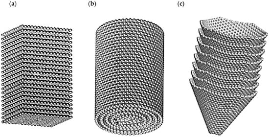
Figure 3. Typical shapes of carbon nano fibers: (a) platelet type; (b) tubular type; (c) fishbone type [33].
The most common technique used for manufacturing CNFs is chemical vapor deposition coupled with thermal of plasma-assisted vapor deposition. Unlike CNTs, chemical vapor deposition of CNFs uses gaseous sources of carbon atoms. Decomposed by a high temperature, carbon atoms are grown into designated shapes by the use of a metallic catalyst [33][35][33,35].
Mechanical properties of carbon nanofibers, while presenting lower values than those of CNTs are still high with Young modulus in the range of 0.4–0.6 TPa and tensile strength of up to 7 GPa [25].
Similar to CNTs, CNFs possess excellent conductive properties due to their elongated shape, which promotes electron movement along the normal axis and the tunneling effect [34].
2.4. Summary of Carbon Nanomaterials
Presented carbon nanomaterials are most commonly used in nano-carbon cementitious composites. While all of them possess excellent mechanical, electrical, and thermal properties, each of them is excels in different applications. Individual features of each of the material provide them with certain advantages over the others. The flattened shape of graphene and its derivatives seem to perform best in promoting hydration, therefore vastly improving the microstructure and tightness of the composite. The elongated, closed shape of CNTs—along with their excellent conductivity—makes them the best choice in terms of conductive smart materials and strain sensors.
Due to variations in methodologies and difficulties in direct measuring of properties of materials in nanoscale, some of the presented properties tend to have significant range of values. It is clear that more precise and unified methods need to be developed in order to assure better ways to compare the performance of individual types of materials and their final quality. The selection of test results for material properties is presented in Table 1.
3. Properties of Carbon Cementitious Composites
As discussed in the previous paragraph, carbon nanomaterials possess a number of unique properties, both mechanical and physical. Most of those properties can be exploited in order to enhance otherwise brittle and non-conductive cementitious materials to create stronger, functional composites. The following sections will provide insight into the most important properties of cementitious composites granted by the addition of carbon nanomaterials.
3.1. Hydration and Workability
Due to strong van der Waals forces between individual particles, carbon nanomaterials tend to accumulate into flocs. This phenomenon, along with a large surface area, causes water molecules to be trapped or absorbed by the nanomaterial, resulting in a reduction in workability. Workability is referred as an ease of flow and pouring of cementitious material. According to standards for cementitious mortars and concrete, workability is measured through comparing the diameter of pool created by a slump test. In this test, a specified amount of mortar of concrete is poured into a cone, then the cone is removed allowing for free flow of the material. Results by Jing et al., obtained from the mini-slump test, are showing that the addition of 0.4% of the binder weight (wt.%) of graphene can reduce workability by 39%. Additional SEM tests have been performed to exclude the influence of poor dispersion on the results [36]. Shuang et al. [37] observed a 40.6% increase in viscosity of cement paste with 0.09 wt.% of graphene by using the viscometer method. They have also ensured low influence of dispersion using UV–absorbance spectroscopy. A study by Konsta-Gdoutos et al. [38] showed an increment in viscosity for cement pastes with the addition of 0.08 wt.% of CNTs. They have also investigated the influence of surfactants and their concentration on the viscosity of the paste. It has been shown best results for a ratio of 5 surfactants to CNT, however, the most optimal ratio, regarding other properties, has been found at 4. Zou et al. [39] estimated the workability of cement paste with 0.038 wt.% and 0.075 wt.% of CNT using the mini-slump test. The decrease of workability was closely related to ultrasonication energy applied at the stage of CNT dispersion.
The workability problem can be mitigated by ensuring the proper dispersion of nanomaterials. If the material is more dispersed, the effects of water adsorption are distributed more evenly among the volume of material. The addition of superplasticizers and ultra-sonication can also efficiently reduce the effect of carbon nanomaterials on the workability of cementitious materials. It is assumed that it can be increased back to levels close to plain cementitious materials [37][38][39][40][41][37,38,39,40,41].
With large specific surface area and water absorption abilities, carbon nanomaterials might accelerate the hydration process through the nucleation effect. Baomin and Shuang [42] reported that the addition of graphene nanoplatelets by 0.06 wt.% exhibit a positive effect on the early stages of the hydration process. Such conclusions are supported by increased hydration heat recorded with isothermal calorimetry curves. Sun et al. [43] compared the degree of hydration of oil well cement doped with cellulose nanofibers and a mix of cellulose nanofibers and GNPs. They have found the best degree of hydration with a mix containing GNPs. The beneficial nucleation effect has also been reported with CNTs [44][45][44,45]. However, other studies suggest that higher amounts of CNTs might actually inhibit the hydration process by separating cement molecules [46]. Therefore, it can be concluded that a certain dosage of carbon nanomaterials promotes the hydration process, densifying material structure.
3.2. Microstructure
The small size of nanomaterials can contribute to improving the microstructure of cementitious materials. Nanomaterials can fill in gaps between C-S-H phase formations, and while enhancing the hydration process, they promote the growth of high stiffness C-S-H phase [12][22][38][47][48][12,22,38,47,48]. This is achieved through the nucleation effect, which causes cement molecules to be attracted to carbon nanomaterials. It is especially well observed with graphene oxide, thanks to the presence of multiple functional groups. As seen in Figure 4, they might promote growth of hydration products into crystal-like formations. [47].
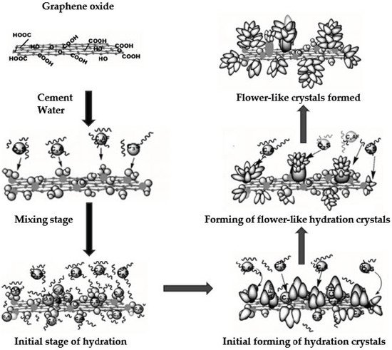
An increase in hydration crystals and their concentration around nanomaterials leads to denser structure and lower pore size on a micro-scale. The results of structure densification can be observed via a scanning electron microscope (SEM) [47][48][47,48].
This kind of refined structure reduces penetration depth for water and aggressive substances, increasing the material’s durability and reducing permeability. Du et al. [49] investigated this mechanism through a rapid chloride penetration test. They have observed a reduction in water permeability, chloride diffusion and chloride migration coefficients by 80%, 80%, and 40%, respectively, for concrete with the addition of 1.5 wt.% of graphene and after 14, 56, and 90 days of immersion in a salt solution. In the cited research, chloride migration coefficient, is a coefficient derived directly from rapid chloride penetration test and is calculated using test parameters including voltage, test time, size of samples, and mean depth of chloride penetration assessed through splitting the sample and spraying it with AgNO3 solution. Chloride diffusion coefficient is a coefficient that is empirically derived, based on chloride diffusion curves. These curves are derived using measured concentration of chlorides on the surface of the sample and consecutive depths of the sample. The diffusion coefficient is then computed by fitting the curve to acquired measurement results.
3.3. Mechanical Properties
Carbon nanomaterials are considered reinforcing phases in cementitious composite materials. Their influence on material strength can be attributed to the aforementioned densifying of microstructure, strong bonding between nanomaterials and cementitious matrix, bridging of nano-sized cracks. Most of the test methodology for assessing cementitious composite’s mechanical properties is derived from both mortar and concrete standard tests as they are a viable way to compare results. For tensile strength, a direct uniaxial tension test on cylindrical or dog bone type of specimen is used. Most of the time, the mechanism of failure for composites is the same pure cement materials. For the same reasons, shapes and dimensions of samples match with corresponding samples advised in mortar and concrete standards respectively. To avoid deviations in results caused by cement additives, ordinary Portland cement is used in tests. Examples of selected experimental results for improvement of compressive, tensile, and flexural strength are summarized in Table 2.
Table 2. Selected results of mechanical properties improvement of cementitious composites for different types of nanomaterials.
| Mechanical Property | Type of Composite | w/b | Increase | Material/Concentration | Reference |
|---|---|---|---|---|---|
| Compressive strength | Cement paste | 0.45 | 28% | GO: 0.04 wt.% | Qureshi et al. [50] |
| Cement paste | 0.3 | 54% | Graphene: 2 vol % | Sun et al. [51] | |
| Cement paste | 0.26 | 38% | GO: 0.05 wt.% | Madbouly et al. [52] | |
| Tensile strength | Mortar | 0.5 | 79% | Graphene 0.05 wt.% | Krystek et al. [12] |
| UHPC | 0.2 | 55% | CNF: 0.3 wt.% | Meng et al. [53] | |
| Flexural strength | Cement paste | 0.45 | 83% | GO: 0.04 wt.% | Qureshi et al. [50] |
| Cement paste | 0.5 | 45% | CNF: 0.048 wt.% | Konsta et al. [54] | |
| Cement paste | 0.3 | 40% | MWCNT: 0.048 wt.% | Konsta et al. [23] | |
| Cement paste | 0.4 | 269% | MWCNT: 0.2 wt.% | Al-Rub et al. [55] | |
| Young modulus | Cement paste | 0.3 | 35% | MWCNT: 0.048 wt.% | Konsta et al. [23] |
| Cement paste | 0.5 | 50% | CNF: 0.048 wt.% | Konsta et al. [54] | |
| Mortar | 0.57 | 100% | GO: 3 wt.% | Horszczaruk et al. [56] |
The Young modulus of carbon nano-infused cementitious composites is improved through the increase in the amount of high stiffness C-S-H phase. Studies show an increase in the value of Young’s modulus by 35% [23] and up to 227% [57]. For CNF reinforced materials, Young modulus increase has been found to be around 50% [54], as for GNP, Horszczaruk et al. [56] reported an increase in Young’s Modulus value of around 100%.
3.4. Electrical Properties
The extraordinary electrical conductivity of carbon nanomaterials can contribute to increasing the conductivity of cementitious composites. Plain cement has a very low electrical conductivity and is considered close to insulators [58]. Including nanomaterials create conducting paths inside the structure of the material. Introduction of electrical conductivity in cementitious materials allows for creation of smart materials, mainly as strain sensors using piezoresistive effect and energy harvesting materials. These functionalities will be covered in more detail in Section 5 of the paper.
There are three main mechanisms for conduction in cementitious nanocomposites. Two of them are related to nanofiller itself. Contact conduction appears simply when individual conductive elements physically contact each other. The other mechanism is tunneling conduction which appears between materials that are close to each other but not in direct contact. It is induced by a strong electrical field appearing around strongly conductive materials, especially those with elongated, fine morphology, e.g., CNTs. The last of the conduction mechanisms is ionic conduction which also appears in plain cementitious materials as it is related to ions dissolved in pores of the material. Generally, this mechanism is relatively weak, especially in dry conditions, therefore, having a small contribution to the overall material’s conductivity [59][60][59,60].
A different approach has been taken by Soliman et al. [61] who attempted to describe conductivity in cementitious materials through mechanisms analogues with diffusivity, linking the conductive mechanisms with tortuosity of conductive paths inside the composite. They have combined their findings into a theoretical dissipation–tortuosity model and stated, that efficiency of smart composites can depend on conductor concentration and electrical tortuosity of the composite.
An increase in conductivity is closely connected with the amount of nanomaterial added and its dispersion. It has been proven that increasing the dosage of carbon nanomaterials effectively increases the material’s conductivity. The conductivity of nanocomposite is often described by percolation theory. The amount at which conductivity is no longer increasing is known as the percolation threshold. Reaching or exceeding this threshold means that the concentration and uniformity of distribution of conductive carbon nanoparticles are enough to create a continuous network of conductive paths [25][62][25,62].
The exact value of the percolation threshold is highly dependent on material type as well as the dispersion method. Du et al. [63] investigated the percolation threshold for GNP infused mortars and found it to be between 2.4 vol % and 3.6 vol %. D’Alessandro et al. [64] investigated a similar problem for MWCNT composites and found the percolation threshold to be 1 wt.% for either cement paste, mortar, and concrete.
Yoo et al. [65] investigated differences in electrical conductivity between CNTs, graphene, and graphite nanofibers at a constant value of 1 vol % for cement paste. The best results in terms of stable, undisturbed response have been achieved with MWCNTs.
The conclusion can be drawn that the previously mentioned elongated shape of CNTs works in their favor not only when considering the conductivity of plain nanomaterial but also in combination with cementitious materials. At the same time, graphene, while having excellent electrical properties in pure form, performs worse in creating conductive paths in cementitious matrix.