The growing demand for renewable energy supply stimulates a drastic increase in the deployment rate of offshore wind energy. Offshore wind power generators are usually supported by large foundation piles that are driven into the seabed with hydraulic impact hammers or vibratory devices. The pile installation process, which is key to the construction of every new wind farm, is hindered by a serious by-product: the underwater noise pollution.
- offshore wind
- pile installation
- underwater noise
- noise levels
- noise mitigation
- air bubble curtain
- sound exposure level
- peak pressure Level
- vibroacoustics
Note: The entry will be online only after author check and submit it.
1. Introduction
Pascal [56][57][56,57]. In The Netherlands, regulations have recently changed from the allowance of piling during specific period of the year to the adoption of specific sound level criteria [58][59][58,59]. The latter are similar to those imposed in Germany, but consider additionally cumulative noise exposure levels. In the United Kingdom, a separate environmental impact assessment (EIA) is followed per project in which acoustic deterrent devices (seal scarers) are used [60] together with trained marine mammal observers who monitor the activity using both visual inspection of the site and passive acoustic detection devices [61][62][61,62]. Similar regulations exist in several other countries and lessons learned from previously gathered experiences slowly find their way into new regulations [63][64][63,64]. The majority of the regulations though do not consider in detail the frequency content of the radiated noise; an item worth further investigation in the near future [65][66][65,66].
2. Structure-Borne Noise in Offshore Piling: The Historical Development of Models
The prediction of underwater noise requires an in-depth study of the source and of the domain in which the acoustic energy is released [67]. Underwater noise in deep oceans is well documented in the literature [68,69,70], driven partly by the need to design SOund Navigation And Ranging (sonar) systems for military applications [71,72]. On the contrary, sound propagation in shallow waters is more complicated due to multiple reflections, refractions and scattering of sound waves at the sea surface and the seabed [73,74,75,76]. The seabed plays a key role here as it is the element that contains the largest uncertainty in the characterisation of its composition [77,78,79].
Next to the challenges associated with wave propagation in shallow waters, the study of noise generated by pile driving, adds an extra complexity; the need to investigate a system composed of three interrelated domains being the seawater, the seabed and the pile, the interaction of which determines the sound source mechanism. Henceforth, a historical overview of the developments in the field of pile vibroacoustics is given, reflecting the evolution of our understanding of the physics of underwater noise emission due to pile driving.
2.1. First Generation Models: The Fluid Approximation of the Seabed
Although some early studies dealing with pile driving noise do exist [80,81,82], Reinhall and Dahl [83] were the first to develop a detailed numerical model focusing on the prediction of underwater noise from impact pile driving. Their approach tackles the problem in two steps: First, a finite element model (FEM) is adopted for the sound generation which includes a sufficient degree of detailing in modelling the source mechanism. Thereafter, the parabolic equation (PE) is applied for the propagation of sound at larger distances [84]. The pile is modelled using structural elements whereas both water and soil are described as linear acoustic fluids. Perfectly Matched Layers (PML) [85] are employed to truncate the fluid domains in the FEM as shown in Figure 2.
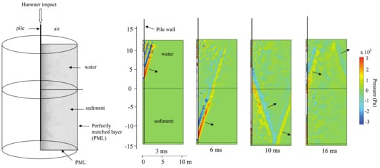
Figure 2. Axisymmetric FE model of pile and water (left). Acoustic pressure surface plots showing the acoustic radiation from the pile at 3, 6, 10 and 16 ms after impact by pile hammer. The propagation direction of the wave front associated with the Mach cones produced in the water and the sediment is indicated by the arrows (right). Reprinted with permission from Reinhall, P.G., Dahl, P.H. Underwater Mach wave radiation from impact pile driving: Theory and observation. The Journal of the Acoustical Society of America 2011, 130, 1209–1216. Copyright 2011, Acoustic Society of America.
The significant result obtained from this study was the observation that the pressure field in the pile proximity is composed of Mach cones, i.e., coherent wave fronts defining alternating zones of compression and rarefaction in the seawater (Figure 2). These are generated by the supersonic compressional stress waves propagating from the pile head to the pile toe right after the hammer impact. Reverse Mach cones were also computed upon reflection of the stress waves from the pile toe. The angle of the cones is equal to sin−1(cw/cp)≈ 17.2° in the seawater and sin−1(cL/cp) ≈ 18.6° in the seabed, with cp, cw and cL being the phase speeds of compressional waves in the pile, water, and seabed, respectively. The physics involved mark essentially a moving source problem which is classical in many field of wave mechanics, i.e., supersonic jets [86] or trains that surpass the speed of Rayleigh waves [87,88]. In the case of pile driving, the stress wave in the pile constitutes the moving source. These observations were soon after confirmed by beam forming analysis of measured data [89,90].
The modelling approach introduced by Reinhall and Dahl [83] was subsequently adopted by other researchers [91,92,93,94,95,96,97], i.e., a FEM was employed for the sound generation and a propagation algorithm was applied for wave field predictions at larger distances. As an alternative to the FEM, MacGillivray [98,99,100] adopted a finite difference (FD) scheme for the near-field acoustics under the simplifying assumption of no bending energy stored in the shell surface. Depending on the degree of detailing required, the far-range propagation model can take several mathematical forms:
- normal mode (NM) representations [97],
- wavenumber intergation (WI) algorithms [91,93,94],
- energy flux-based methods [101] and
- parabolic equation (PE) models [83,96,102,103].
Numerical models which couple the structural domain modelled by finite elements and the exterior (soil) domain modelled by means of the boundary element method also exist [104,105,106], albeit their focus is primarily placed on the soil vibrations in the pile proximity.
In contrast to the models described above, which are primarily based on numerical discretisation of the partial differential equations, semi-analytical solutions were also proposed by several authors [107,108,109,110,111,112]. The analytical model by Hall [110] considers a thin cylindrical shell immersed in a fluid in which semi-analytical solutions are obtained for the radiated sound pressure and particle velocity similar to Junger and Feit [113].
In the model by Tsouvalas and Metrikine [107] (Figure 3), the pile is modelled using the shell theory, the water is described as a linearised acoustic fluid and the soil is treated by distributed springs and dashpots attached to the pile surface. The shell and water responses are expressed in terms of modes and then a mode matching technique is employed to solve the coupled problem. The models by Deng et al. [111], Deng et al. [112] are similar to those in [107], but expand the shell response in terms of different basis functions. The advantage of the semi-analytical models is that they are computationally fast and can be used when a large number of simulations are required. The downside of this is that they are not able to achieve the same degree of detailing as in FEM.
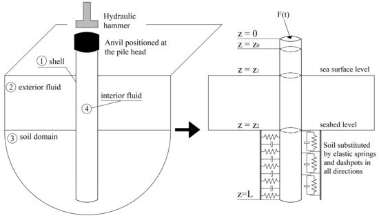
Figure 3. Model proposed by Tsouvalas and Metrikine [107] to treat the pile–water–soil interaction and the generation of sound in the seawater. Inner fluid occupies the region z0≤z≤Lwhile the outer fluid domain the region z1≤z≤z2. Soil reaction to the pile is represented by distributed spring-dashpot elements attached on the pile surface at z2≤z≤L. Reprinted from Tsouvalas, A., Metrikine, A.V. A semi-analytical model for the prediction of underwater noise from offshore pile driving. Journal of Sound and Vibration 2013, 332, 3232–3257. Copyright 2013, with permission from Elsevier.
2.2. Second Generation Models: Inclusion of the Elastic Seabed
The models described in Section 2.1 constitute a significant step towards understanding the physics of underwater sound emission in impact piling. However, their main limitation is that they describe the seabed either by an acoustic medium or by spring-dashpot elements. The former approximation, albeit reasonable in many ocean acoustic applications, cannot capture all the essential physics of the problem at hand for two main reasons. First, the energy is largely released in the seabed during pile driving while the pile is partly embedded into the soil [114]. Thus, an accurate prediction of the energy flux in the surrounding acousto-elastic region requires a detailed description of the seabed next to that of the seawater. Second, the accurate identification of the acoustic source amplitude, i.e., pile response, requires the consideration of the coupled soil–fluid–pile problem. In other words, without an accurate description of the coupled problem, the noise source mechanism cannot be identified properly.
Tsouvalas et al. [115,116,117,118] were among the first to include the elastic description of the seabed in the pile driving acoustics. In Figure 4, results of model simulations are shown for illustration of the physics of the wave radiation pattern for a typical case of an offshore pile installation scenario. Next to the pressure cones in the seawater, the response in the soil is dominated by shear waves with almost vertical polarisation because the shock waves in the pile travel at hypersonic speed compared to that of the shear waves in the soil (M=cp/cS≈27). Additionally, compressional waves exist in the seabed similar to the ones observed in the seawater. Apart from the waves travelling in the bulk of the media, Scholte waves are generated at the seabed–water interface travelling with much lower speed compared to the speed of the compressional waves. The prediction of these elastic waves was later confirmed by several authors [119,120,121,122,123], while experimental data measuring the soil response together with the pressures in the water column close to the seabed have confirmed the existence of the interface waves [124,125].
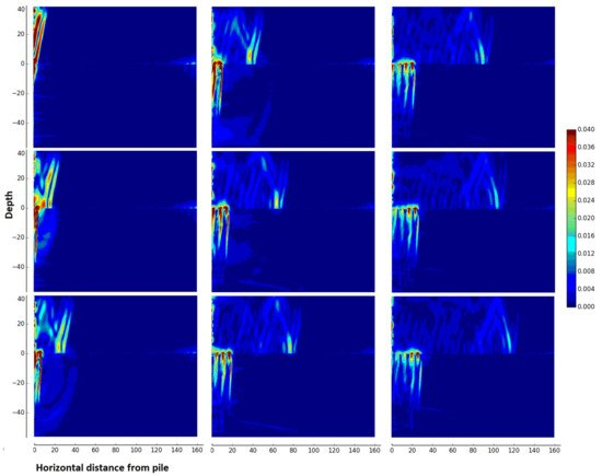
Figure 4. Evolution of the particle velocity norm in the seawater (z≥0 m) and the seabed (z<0 m) for several moments in time after the hammer impact using the model by Tsouvalas and Metrikine [115]. In the case analysed, the pile has a diameter of 7 m and a length of 78 m and the seabed consists of a soft upper soil layer overlying a stiffer soil halfspace. The time increases from top to bottom and from left to right.