The deposit-forming problem is one of the main bottlenecks restricting the yield and production benefit of iron ore pellets produced by coal-fired rotary kilns. In order to implement measures to ensure the efficient production of pellets by coal-fired rotary kilns, the mechanism and influencing factors on the deposit formation were reviewed. The pellet powder and coal ash come together to form the material base of the deposit.
- rotary kiln
- pulverized coal
- pellets
- combustion efficiency
- deposit formation
- liquid phase
1. Introduction
As an important component of ironmaking charge, pellets are characterized by their high grade, uniform particle size, better strength and metallurgical performance than natural lump ores and sinters; the advantages in environmental protection and energy conservation are especially obvious [1].
2. Formation Mechanism of Deposit in Coal-Fired Rotary Kiln
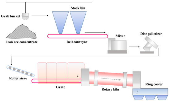
The grate-kiln process includes pelletizing, drying-preheating, roasting and cooling of pellets, which is carried out by pelletizer, grate, rotary kiln and cooler respectively [2][3][17,18]. These devices are connected in series to form a complete pellet production line. High grade (>60%) iron concentrate powder is mixed with a binder, flux, and fly ash to prepare green pellets with the particle size of 8~16mm by the disc pelletizer, and then evenly distributed on the grate machine for subsequent processing [4][19]. Figure 1 shows the schematic diagram of the grate-kiln process in a pelletizing plant in China [5][20]. Grates, rotary kilns and ring coolers are all large production equipment, which usually has no standby facility to take its place. Therefore, when these facilities break down and need to be shut down for maintenance, it will result in serious impacts on the pellet production. Thus, the researches on deposit of rotary kilns has great significance to the wide application of the grate-kiln process.
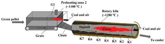
The distribution of deposits in a grate and rotary kiln is mainly affected by pulverized coal injection and temperature field [6][7][21,22]. As shown in Figure 2 , at the heads of the rotary kiln, pulverized coal is sprayed with high-pressure air and burned to provide heat for the drying, oxidation and consolidation of pellets. In addition, the high-temperature exhaust gas from the cooler serves as the secondary air to provide a stable temperature field for the grate and the rotary kiln [8][23]. Influenced by the flame shape generated by pulverized coal combustion, the temperature in the middle of the rotary kiln is usually higher than that in the head and tail of the kiln [9][10][24,25]. Therefore, the deposit-forming phenomenon in the middle of the kiln is more pronounced. In previous experiments, we selected the sediments from different regions of the grate and rotary kiln for chemical element composition analysis, as shown in Table 1 [11][12][2,26]. The obtained results indicate that the total iron content from K1 to K7 showed a decreasing trend, while the contents of K, Na and Si increased gradually. This study confirmed that the distribution regularity of chemical composition of deposit in the rotary kiln was mainly affected by pulverized coal injection. The residual coal ash produced by pulverized coal combustion is driven by hot air to the kiln tail, which makes the deposit in the K4-K7 region contain more coal ash components, while the chemical composition of the deposit in the K1-K3 region is similar to pellets.
| No. | TFe | SiO | 2 | CaO | Al | 2 | O | 3 | MgO | K | 2 | O | Na | 2 | O | S |
|---|---|---|---|---|---|---|---|---|---|---|---|---|---|---|---|---|
| G1 | 55.78 | 9.12 | 3.03 | 5.07 | 1.26 | 0.29 | 0.25 | 0.0050 | ||||||||
| K1 | 66.04 | 2.51 | 1.74 | 1.53 | 0.81 | 0.043 | 0.058 | 0.0050 | ||||||||
| K2 | 66.40 | 2.66 | 1.95 | 1.30 | 0.88 | 0.042 | 0.070 | 0.0050 | ||||||||
| K3 | 64.22 | 4.05 | 1.91 | 1.91 | 0.93 | 0.062 | 0.095 | 0.0055 | ||||||||
| K4 | 62.98 | 5.19 | 2.45 | 2.46 | 0.85 | 0.088 | 0.120 | 0.0050 | ||||||||
| K5 | 61.93 | 5.91 | 2.41 | 2.25 | 1.37 | 0.089 | 0.160 | 0.0070 | ||||||||
| K6 | 62.11 | 5.72 | 1.91 | 2.36 | 0.79 | 0.110 | 0.640 | 0.0023 | ||||||||
| K7 | 62.60 | 5.72 | 2.02 | 2.11 | 0.90 | 0.082 | 0.19 | 0.0020 |
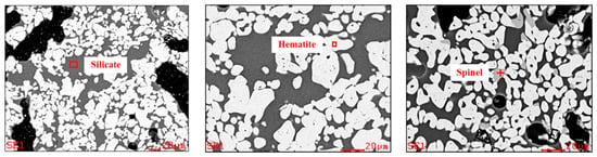
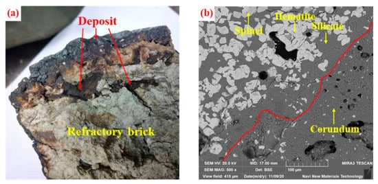
Figure 34 shows the microstructure of the rotary kiln deposit of iron ore pellets. The deposits are usually composed of hematite, silicate (hedenbergite and anorthite) , spinel [13][27]. In the process of high-temperature roasting, hematite particles from preheated pellet powder adhere together in the molten silicate binding phase to form the microstructure of deposits in rotary kiln [14][31]. The binding phase is composed predominantly of SiO 2, CaO, Al 2O 3, MgO and Fe 2O 3. Because of the better fluidity, the silicate melt depends on its own gravity and the rotary kiln centrifugal force to continuously deposit on the kiln lining, which results in the deposit microstructure becoming denser [15][32]. Meanwhile, the combustion of fixed carbon in the incomplete burned pulverized coal produces a local reducing atmosphere in the pellet powder, which reduces Fe 3+ to Fe 2+ . Then, the Fe 2+ reacts with MgO and Al 2O 3 to form spinel [12][26]. In general, the microstructure formed by the bonding of silicate melt with hematite and spinel has high strength, which makes it difficult to be completely destroyed by the friction and collision from the rolling pellet layer [16][33].
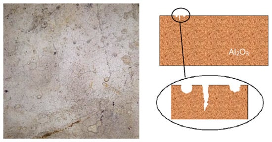
The refractory material of the lining in the coal-fired rotary kiln is usually composed of corundum and mullite [17][18][34,35]. Previous studies have analyzed the process of deposit adhesion and penetration on refractory bricks [19][36]. The adhesion of the deposit first occurs at the defects on the refractory brick surface. As shown in Figure 45 , due to the thermal impact in the process of high-temperature roasting, the surface temperature of refractory bricks is too high to produce the “separation” phenomenon, which results in cracks [20][37]. The deposits formed by preheated pellet powder and incomplete burned pulverized coal preferentially accumulate at these defects. The testing of rotary kiln lining refractory bricks used for 14 months reveals a minimal amount of silicate glassy phases around corundum particles on the bricks’ surface, which indicates that the penetration of the sedimentary liquid phase is not apparent at this time. After four years of usage, the surface of refractory bricks adheres to a thicker hematite layer. Meanwhile, due to the erosion of the liquid phase, part of the corundum particles are released, migrate to the hematite layer and react with hematite to form a spinel-type solid solution [15][32]. From Figure 56 a, we can clearly observe the adhesion and erosion of deposits to refractory materials. From Figure 56 b, as the service of rotary kiln lining refractory bricks continues, the grain boundary between the hematite layer and the corundum layer becomes indistinguishable. Affected by the infiltration of the molten liquid phase, hematite and corundum particles migrate between deposits and refractories. In addition, when the deposits grow enough to affect the pellet production, it is necessary to frequently stop the operation of the rotary kiln to remove them. In the cooling process of rotary kiln, the volume contraction of the silicate glass phase will generate cracks and fracture surfaces in the deposits. With the kiln rotating, large chunks of deposits fall off the lining to be discharged under the influence of gravity. The erosion effect of the deposits makes them closely connected with the refractory brick. Because of the weak tensile strength, with the shedding of deposits, the surface layer of refractory materials may be separated to shorten their service life [21][38].
3. The Factors Affecting Deposit Formation
The pellet powder is the material base of deposit formation in a rotary kiln, which comes from the following sources. When the moist green pellets enter the drying region of the grate, the higher temperature and the slow air flow speed may cause the water vapor inside the green pellets not to be eliminated in time, which will aggravate the internal stress and make the green pellets break into a large amount of powder [22][23][44,45]. Some of the fragmentized powder is returned to the pelletizing system, and the rest is sent to the rotary kiln with the preheated pellets. In addition, due to collision and friction between preheated pellets during the rotating process with the kiln, the powder that is not firmly consolidated on the surface of the pellets will fall into the material layer [24][46]. The increase of preheated pellet powder in the material layer will lead to more hematite particles adhering to the surface of the deposits [25][47]. Therefore, in order to slow down the accumulation of hematite particles on the deposit surface, methods of improving the strength and adjusting the moisture content of green pellets, as well as selecting the appropriate drying temperature and pellet layer thickness should be adopted.
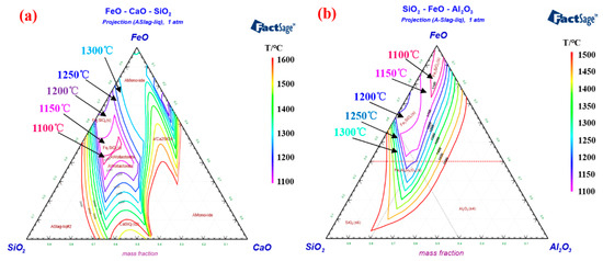
In the roasting process, a stable rotary kiln temperature is usually required to ensure smooth production [22][44]. However, for pelletizing plants with unstable ore sources, the composition of iron concentrate changes frequently, forcing operators to adjust the temperature of the rotary kiln to improve the performance of roasting pellets [26][57]. Importantly, the melting point of the deposit-forming silicate is close to the roasting temperature range of iron ore pellets. An improper adjustment operation of the rotary kiln temperature may cause further aggravation of the deposit-forming problem. Factsage software provides phase diagram calculation of multi-component systems [27][58], which can be used to obtain the isothermal cross-section of liquid phase formed by different component contents in the deposit. The isotherm distribution of ternary phase diagrams of FeO-CaO-SiO 2 and FeO-Al 2O 3-SiO 2 are shown in Figure 69 a,b, respectively. The phase diagram shows the wide liquid isothermal sections in the temperature range of 1100 °C to 1600 °C. It is worth noting that as the temperature of the isotherm increase, the proportion of the isotherm section gradually expands. When the rotary kiln temperature rises to the melting point of silicate in the deposit, the liquid phase will form on the deposit surface and continuously adhere to the powder from the pellet layer [16][33]. The high-temperature roasting can promote the microcrystalline link of hematite and enhance the consolidation strength of the iron ore pellets. Therefore, increasing the roasting temperature is a “double-edged sword”, which can improve the pellet performance and aggravate the deposit-forming when the grate-kiln method is used to produce pellets. We can adopt the grate-kiln “Expert System” to select the appropriate roasting temperature intelligently, which can not only ensure the physical properties of oxidized pellets, but also inhibit the growth of deposit formation. This system consists of five parts, respectively, data preprocessing, simulation model, knowledge base, inference engine and global database. The “Expert System” software is programmed and developed by Visual C++, which would realize stable production by controlling the temperature of the pellet roasting in the kiln [28][29][59,60].
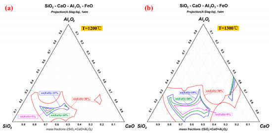
After the combustion of pulverized coal injection, the Fe content in the remaining products is usually less than 10wt%, which could prevent the iron-containing liquid phase from forming in large quantities. However, the incorporation of pellet powder makes the content of Fe increase rapidly, which provides the material basis for deposit formation [14][31]. The continued combustion of residual carbon results in the reduction of hematite to magnetite (Fe 3O 4) and wustite (FeO) [30][31][61,62]. FeO reacts with SiO 2 to form stable low-melting-point compound fayalite (Fe 2SiO 4) [32][63]. Due to the fact that the melting point is lower than the pellets roasting temperature, Fe 2SiO 4 is considered to be the major component further forming the liquid phase in the deposit. In contrast, hematite usually requires the participation of Ca 2+ and Al 3+ to react with SiO 2. Figure 710 a, b calculate the isotherm distribution of SiO 2-CaO-Al 2O 3-FeO quaternary phase diagram at 1200 °C and 1300 °C respectively. With the increase of FeO content, the area of the isothermal cross section expands sharply. This study confirms the importance of FeO content for the formation of liquid phase in the initial deposit [33][10]. In the process of high-temperature roasting, the silicate liquid phase containing Fe 2+ will not only continuously corrode the kiln lining refractory brick, but also cause the pellet powder adhering on new deposits. Meanwhile, the solidified silicate glassy phase further improves the strength of the deposits.
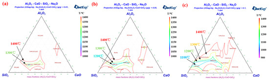
Alkali metal elements of the rotary kiln system mainly exist in the pulverized coal and iron concentrate [34][64], which are brought by coal ash and pellets powder into the deposits [35][65]. The presence of Na and K can be found in the chemical element detection of deposits [36][37][66,67]. Due to the fact that alkali metals can form low melting point substances with other compounds [38][68], they have an important influence on deposit formation [39][69]. During the liquid phase deposition, Na + and K + enter the silicate phase together with Al 3+ , Ca 2+ , Fe 2+ and Fe 3+ . Moreover, alkali metals have a high affinity for Al 3+ [40][70], thus corrode refractory bricks containing corundum and mullite [41][71]. Figure 811 a– c displays the isotherm distribution of the Al 2O 3-CaO-SiO 2-Na 2O quaternary phase diagram with 0.01%, 0.05% and 0.1% Na 2O addition, respectively. As the amount of Na 2O increases, the isothermal cross-section area in the range of 1000–1400 °C of the quaternary phase diagram expands noticeably. Although a small amount of Na 2O was added, the liquid phase formation in the Al 2O 3-CaO-SiO 2-Na 2O quaternary system was significantly promoted [22][44]. According to results researched by Kejiang Li et al. [42][72], the presence of Na 2O can significantly reduce the viscosity of the aluminosilicate liquid phase, which is attributed to the fact that Na + will connect with O 2− to form non-bridged oxygen [43][73]. The increase of the aluminosilicate liquid phase fluidity will intensify the erosion in the refractory brick and enhance the adhesion property of the deposits [44][28]. In order to limit the formation of liquid phase, we need to reduce the input of alkali metal elements from coal ash and pellets powder. Thus, it is recommended that high-quality iron concentrate and coal with low alkali metals should be chosen for controlling the deposit formation.