Your browser does not fully support modern features. Please upgrade for a smoother experience.
Please note this is a comparison between Version 1 by Jan Baeyens and Version 2 by Bruce Ren.
The steel industry represents about 7% of the world’s anthropogenic CO2 emissions due to the high use of fossil fuels. The CO2-lean direct reduction of iron ore with hydrogen is considered to offer a high potential to reduce CO2 emissions, and this direct reduction of Fe2O3 powder is investigated in this research.
- hydrogen
- iron ore
- direct reduction
- fluidized bed
- solar energy
Note: The following contents are extract from your paper. The entry will be online only after author check and submit it.
1. Introduction
1.1. Background Information
Most steel mills are currently using the blast furnace principle, fuelled by mostly coal, coke, and coke oven gas. The successive processes of sinter belt, blast furnace, and converter operate at extremely high temperatures, hence being energy-intensive and producing significant amounts of CO2. The steel industry represents about 7% of the world’s anthropogenic CO2 emissions. Within the objectives of COP21 (Paris, 2015), the target of steel mills is to reduce the CO2 emissions from the current (nearly) 3000 Mton/year to below 500 Mton/year. The use of renewable energy sources is, hence, a topic of major development, and ultimately the CO2-lean direct reduction of iron ore with hydrogen is considered to offer high potential. Two alternative direct H2 ore reductions (Figure 1, right-side) and the traditional fossil-fuel blast furnace operation (Figure 1, left-side) are illustrated in Figure 1 below.
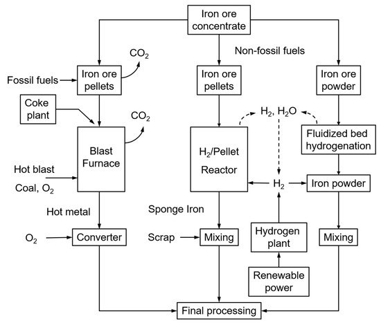
Figure 1. Different steel-making processes: traditional, using fossil fuels (left); H2-driven (right).
Whereas the production of sponge iron from iron ore pellets is already commercially applied, the direct H2 reduction of crude iron ore powder has the advantages of omitting the sintering stage that is the major energy consumer and CO2 emission source of the iron-making process, together with the blast furnace. Sintering is indeed required to produce a sinter cake to be loaded into the blast furnace. It thermally agglomerates the mixture of iron ore fines, recycled iron-making products, fluxes, slag-forming agents, and solid fuel (coke) at a temperature between 1300 and 1480 °C. Omitting the sintering operation will hence reduce the overall energy consumption and CO2 emissions by 35 to 40% [1].
The main reasons behind researching the reduction of CO2 using hydrogen are based upon limiting both the required thermal energy and the associated CO2 emissions.
Major developments were reported since 2015, with research efforts illustrated in Figure 2. This figure was established from Web of Science statistics with appropriate keywords. Over 70% of the research dealt with the fundamentals of direct ore reduction using hydrogen and the reactors to be used (rotary furnace, plasma, fixed and fluidized beds). Additional publications tentatively focused upon process economics and environmental benefits. The fixed/moving or fluidized bed reactors represent only 7 out of 28 papers (see Table 1), stressing the need for additional research, as dealt with in the present study.
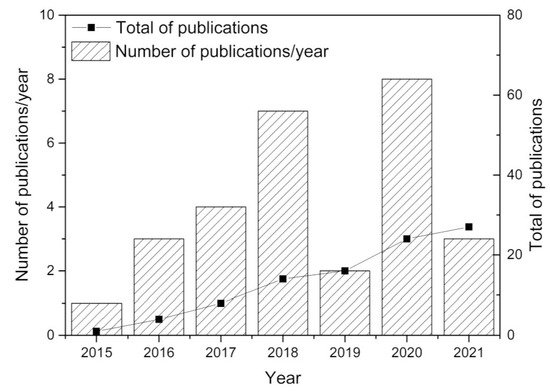
Figure 2. Review of publications since 2015, from Web of Science, with keywords iron ore, direct reduction, hydrogen, CO2 reduction.
Table 1. Important research contributions since 2017.
| References | Major Findings | ||||||||
|---|---|---|---|---|---|---|---|---|---|
| Hydrogen reduction of iron ores | |||||||||
| Sohn et al. [ | 2 | ] | Developed a novel iron-making technology based on fine iron ore concentrate in a flash reactor. Optimization towards using multiple burners, preheating the feed gas, or both is examined. | ||||||
| Abolpour et al. [ | 3 | ] | Studied the reaction kinetics of H | 2 | reduction of iron ore concentrate particles between 700 and 900 °C. | ||||
| Murakami et al. [ | 4 | ] | Studied the effect of H | 2 | concentration in the reducing gas on the changes in mineral phases during reduction of iron ore sinter. The mineral composition of 10 types of sinter samples was analyzed. | ||||
| Patisson & Mirgauxb [ | 5 | ] | Analyzed a new route for making steel from iron ore based on the use of H | 2 | , with a 90% reduction in CO | 2 | emissions compared to those of the blast-furnace route. | ||
| Zhang et al. [ | 6 | ] | Described the reduction kinetics by a pellet-scale single-interface shrinking core model at temperatures below 1143 K. At higher temperatures, the rate-limiting step is the interfacial chemical reaction process. | ||||||
| Bai et al. [ | 7 | ] | Investigated the thermal reduction of pellets by H | 2 | . An un-reacted core and interfacial chemical reaction are reaction rate controlling steps in function of the operating temperature. | ||||
| Wei et al. [ | 8 | ] | Conducted reduction experiments with a H | 2 | -N | 2 | mixture in a rotary drum reactor. A dense, increasingly thick layer of iron was formed during the reduction reaction. The reduction process was controlled by a first-order reaction model. | ||
| Bai et al. [ | 9 | ] | Studied the direct reduction behavior and dynamic characteristics of oxidized pellets under the 75% H | 2 | -25% N | 2 | atmosphere at 760, 900, 1000 °C. Holes and cracks were observed at higher temperature, hampering the reduction degradation behavior of the pellets. | ||
| Lyu et al. [ | 10 | ] | Investigated the effect of hydrogen addition on gas utilization in a blast furnace. The H | 2 | content should be controlled in the range of 5%–10%. | ||||
| Elzohiery et al. [ | 11 | ] | Demonstrated that the reduction is of a first-order dependence with the hydrogen partial pressure. | ||||||
| Du et al. [ | 12 | ] | Proposed a new process that could simultaneously enrich CH | 4 | from coke oven gas and produce separated magnetite from low-grade hematite. | ||||
| Sohn et al. [ | 13 | ] | Reduced the concentrate by H | 2 | and CO gas mixtures formed from the partial oxidation of natural gas in a flash reactor. The rate equations were applied to experimental results from a laboratory flash reactor using CFD simulation. | ||||
| Htet et al. [ | 14 | ] | Investigated the gasification reactivity of carbon black compared to the carbonaceous materials used in the HIsarna process by TGA method at 1250 °C, 1350 °C and 1450 °C under atmospheric pressure. Carbon black is less reactive than thermal coal and charcoal. The random pore model best describes the gasification reaction of the selected samples. Activation energies were determined. | ||||||
| Energetic and environmental importance of H2-based steel production | |||||||||
| Bhaskar et al. [ | 15 | ] | Developed a mass and energy flow model based upon Python to explore the feasibility of using H | 2 | - direct reduction of iron ore (HDRI) coupled with an electric arc furnace (EAF) for carbon-free steel production. This technology could reduce specific emissions from steel production in the EU by more than 35%, at present grid emission levels (295 kgCO | 2 | /MWh). | ||
| Vogl et al. [ | 16 | ] | Hydrogen direct reduction (H-DR) steelmaking needs 3.48 MWh of electricity per ton of liquid steel, mainly for the electrolytic hydrogen production. H-DR emits only 2.8% of blast furnace CO | 2 | . | ||||
| Mixed/moving and fluidized bed direct reduction reactors | |||||||||
| He et al. [ | 17 | ] | Investigated the micro-fluidized bed reduction behavior of Brazilian hematite in 20% H | 2 | and 80% Ar at 400–570 °C. The reaction rate was suggested to be determined by the phase boundary reaction. | ||||
| Spreitzer & Schenk [ | 18 | ] | Investigated the fluidization behavior and reducibility of various iron ore grades. A stable fluidization of hematite- and limonite-based iron ores was observed, while magnetite-based iron ore could not be fluidized. | ||||||
| Knop and Kubiak [ | 19 | ] | Studies the comparison of a combined H2-based direct reduction and electric steelmaking, and the ore-fines reduction in a novel fluidized bed process. | ||||||
| Hamadeh et al. [ | 20 | ] | Studied the moving bed principle in de direct reduction shaft furnace, providing evidence of 8 different zones according to the predominant thermal and reaction characteristics. | ||||||
| da Costa et al. [ | 21 | ] | In a counter-current direct-reduction moving bed reactor, CO | 2 | emissions were reduced by more than 80%. | ||||
| Lazou et al. [ | 22 | ] | Studied the CO | 2 | reduction in the conventional Pedersen Process by reducing iron or bauxite ore at temperatures below and above 560 °C. At temperatures above 860 °C, the formation of FeAl | 2 | O | 4 | retards the reduction to metallic iron. |
| Moldenauer et al. [ | 23 | ] | A circulating fluidized bed reactor was applied in a chemical looping combustion. CO | 2 | reductions of 75 to 92% were achieved. | ||||
Some selected and important publications are listed in Table 1 according to their main output. Research on fixed/moving or fluidized ore reduction was separately included in the Table. The solar energy potential was not previously reported upon.
Similar research efforts on reducing the CO2 emissions from thermal processes were also presented for different fields, with a specific target of CO2 modeling, such as in a large-scale coal-fired thermal power plant [24], in integrated processing of liquified natural gas [25], in a multigeneration cascade system [26], in the pyrolysis reaction of lignocellulosic waste [27], or through the integration of rigid porous high-temperature filters in thermal processes [28], among others.
1.2. Objectives, Structure, and Contribution of the Reported Research
From the literature survey, it is clear that the direct H2-driven reduction of iron ore, and the considerably lower CO2 emissions, are increasingly important. The previous research developed some fundamental principles about the reaction mechanisms, reduction kinetics and CO2 reduction potential, as also dealt with in several studies about CO2 modeling. The importance of using a zero CO2 emission H2 as a fuel toward CO2 abatement in comparison with common fossil fuels is illustrated in Figure 3.
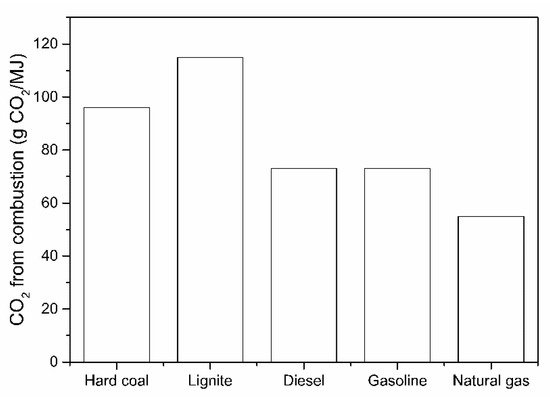
Figure 3. CO2 emissions when burning an equivalent energy unit of fuel.
The application of fluidized bed reactors in this direct reduction principle of iron ores was only scarcely investigated. The application of sustainable solar energy was not investigated. To complete and assess the previous findings, and develop the perspective of concentrated solar energy application in the fluidized bed to direct H2 reductions of iron ore, this paper has multiple objectives.
2. Potential “Green” H2 Production Methods
2.1. NH3 Decomposition
Liquid NH3 can be considered an H2 storage medium and can be decomposed to N2 and H2. Although this decomposition is currently being tested, the literature provides sufficient background data to assess the reaction feasibility.
Electrolysis and thermo-chemical processes can be utilized for NH3 decomposition. The thermo-chemical decomposition of NH3 involves a catalyst inside a reactor using a reaction as follows:
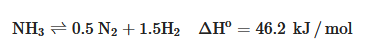
The decomposition reaction is an endothermic thermochemical reaction that requires high temperatures, around 250–700 °C, and relatively high NH3 partial pressures [36].
Theoretically, the thermodynamic equilibrium calculation produces the single-pass conversion rate at different decomposition temperatures, as presented in Table 4. The decomposition can reach a complete reaction with a conversion rate of 99% at a temperature of at least 400 °C. Higher temperatures above 450 °C no longer strongly influence the reaction but rather its kinetics [36].
Table 2. Equilibrium NH3 decomposition (at 1 bar) as a function of temperature, with original data from [36].
| Temperature (°C) | NH | 3 | Conversion (%) |
|---|---|---|---|
| 300 | 95.7 | ||
| 400 | 99.1 | ||
| 500 | 99.7 | ||
| 600 | 99.9 |
Recent studies reported various single metal catalyst, in terms of activity, in the decreasing order Ru > Ni > Rh > Co > Ir >Fe > Pt > Cr > Pd > Cu >> Te, Se, Pb [37]. However, even if Ru shows the best conversion activity, this type of catalyst is still not sufficiently active for NH3 decomposition at a temperature of 450 °C. More importantly, it will not be economically viable for large-scale applications. Multiple sources state that the Ru-based catalyst is active at a temperature of decomposition over 600 °C with a conversion rate of 97%.
Research and development of catalysts are done on precious metals, bimetallic materials, and metal oxides [38,39,40,41,42]. The bimetallic compound is proven to improve catalytic performance even though the manufacturing is complicated. It was also shown that metal oxides work by changing the electronic density of the active catalyst sites, and hence, are proposed as promoters and supporting materials for catalysts.
2.2. C2H5OH and CH3OH Catalytic Decomposition
Results are shown in Figure 4 below for an ethanol/water mixture (1 to 6 mol-ratio), at a feed rate of 0.1 mL/min of ethanol/water and using two different catalysts, i.e., MnFe2O4 and a Co-loaded Al2O3.
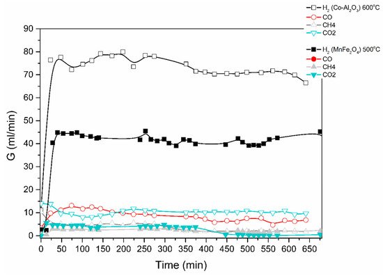
Figure 4. Catalytic decomposition of ethanol-water (1:6) mixture using Co-Al2O3 or MnFe2O4 catalyst. Results obtained in the electric furnace at the given temperatures.
The produced gas stream was continuously monitored by a gas chromatograph. The lag time of about 25 min is due to the piping between the reactor outlet and the GC. H2, CO, CO2 and CH4 were the main products identified; acetone was also detected. The reaction mechanisms are currently under investigation.
A similar procedure was applied for the steam-methanol decomposition, with results illustrated in Figure 5 and Figure 6. No coking of the catalyst was observed, and up to 5 repeat experiments for the same length of time and at successive days yield the same H2 production rates.
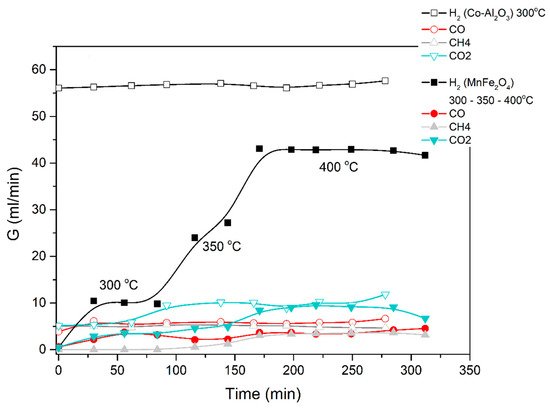
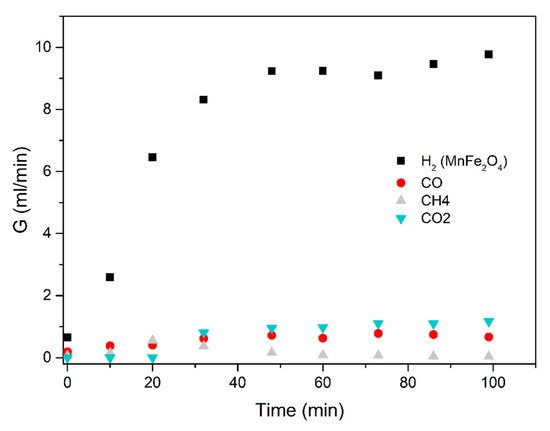
Figure 5. Catalytic decomposition of methanol-water (1:3) mixture using Co-Al2O3 or MnFe2O4 catalyst. Results obtained in the electric furnace at the given temperatures.
Figure 6. Methanol-water (1:3 mixture) using the MnFe2O4 catalyst. Results obtained in the electric furnace at 300 °C.
The average results of three repeat experiments are used in the figures below. The deviation between the repeat results and the averages were below 10%, accepted as fair in view of the lag time in the reactor-to-GC piping.
The results obtained demonstrate that excellent ethanol/methanol to H2 conversions are achieved at low temperatures (300 to 500 °C is sufficient). In all the cases studied, the ratio of volumetric H2 to CO2 production was very high. Most of the feedstock carbon was detected as CO, CH4 and acetone.
2.3. Tentative Techno-Economic Comparison of Different H2 Production Technologies
From the experimental data and literature reports, the following comparison emerges (Table 5) for the levelized cost of hydrogen production (LCOH), for the GHG emission reduction potential and for the H2 yield. Current production techniques of methane steam reforming, coal and biomass gasification and water electrolysis (using a renewable electricity source from wind turbines or photovoltaics) are compared with the novel methanol, methane and ethanol decomposition reactions.
Table 3. Techno-economic comparison (2017–2021).
| Methane Steam Reforming | Coal Gasification | Membrane Electrolysis (Renewable Energy) | Biomass Gasification | Methanol Steam Reforming | Ethanol Steam Reforming | Methane Decomposition | |||||
|---|---|---|---|---|---|---|---|---|---|---|---|
| LCOH ($/kg H | 2 | ) | 1.25 | 1.5 | 7.7 | 3 (for large scale) Otherwise > 5 |
1.8–2.2 | 1.5–2.0 (if acetone can be recovered and sold) | 1.0–1.5 (if carbon black can be sold at 250–1000 $/ton) | ||
| GHG emission (kg CO | 2 | -eq/kg H | 2 | ) | 8.1–11 | 13–17 | 0 | +/−0 | >7 | 5–7 | 2.5 |
| H | 2 | yield (%) | 70–85 | 50–60 | 70 | 20–40 | >90 | 60–80 | 75–80 |
From this summary table, it is clear that (i) biomass and coal gasification should be avoided because of the low H2 yield and fairly high LCOH; (ii) all other systems have a fairly similar H2 yield, although the GHG emission levels disfavor methane steam reforming and coal gasification; methane, methanol and ethanol decomposition reactions can reduce the CHG emission levels, while still achieving a competitive LCOH.