Rotational Piezoelectric Energy Harvesting (RPZTEH) is widely used due to mechanical rotational input power availability in industrial and natural environments. This paper reviews the recent studies and research in RPZTEH based on its excitation elements and design and their influence on performance. It presents different groups for comparison according to their mechanical inputs and applications, such as fluid (air or water) movement, human motion, rotational vehicle tires, and other rotational operational principal including gears. The work emphasises the discussion of different types of excitations elements, such as mass weight, magnetic force, gravity force, centrifugal force, gears teeth, and impact force, to show their effect on enhancing output power. It revealed that a small compact design with the use of magnetic, gravity, and centrifugal forces as excitation elements and a fixed piezoelectric to avoid a slip ring had a good influence on output power optimisation. One of the interesting designs that future works should focus on is using gear for frequency up-conversion to enhance output power density and keep the design simple and compact.
- piezoelectric
- rotational energy harvesting
- energy harvester excitation elements
- rotational energy harvester design
- factors affecting energy harvester performance
1. Introduction
Energy harvesting is defined as the process of converting mechanical energy such as distortion energy, vibration, or other kinetic energy into electrical energy [1]. Fast development in wireless sensor networks (WSN), and storage power with better efficiency solutions will finally increase using of self-power devices in health care, monitoring of the environment, and automotive applications [2]. However, limitation of power source and batteries, such as volume, weight, and short lifetime, which is much less than the WSN life, changing the batteries frequently, and devices in hard reach area [3]. All these limitations make the powering of microdevices and WSNs using energy harvester considering a feasible approach in our environment due to its small size, low power consumption, and special working environment [4][5][4,5].
Piezoelectric energy harvesting is one of the innovative approaches that has been evolved and implemented for harvesting power for microdevices using different types of mechanical power sources [6]. Most of the previously published review papers mentioned rotational piezoelectric energy harvesting partly and focused mainly on frequency up-conversion or bandwidth widening [2][7][8][9][10][11][12][2,67,68,69,70,71,72].
The Rotational Piezoelectric Energy Harvesting (RPZTEH) operation principle is based on the plucking of piezoelectric for excitation, which results in piezoelectric vibration, bending, or pressing, and thus voltage is generated. This plucking could be done using different excitation elements.
2. Methodology
In the present rentryview, the comparisons of excitation elements, design and their influence on performance are divided into four types according to mechanical inputs: fluids (air, water) movement, human motion, rotational vehicle tires, and other rotational operational principals. For each one, mechanical inputs, excitation type, design, methodology, and wiring have been characterised and thoroughly reviewed. The type of excitation has been subdivided according to excitation elements, such as mass, gear, magnetic, spring, centrifugal, gravity and impact forces. Each group may contain one or more of the excitation elements to conclude which group has the maximum influence on rotational piezoelectric energy harvesting enhancement. The design comparison also discusses the piezoelectric rotation, which may affect the type of wiring for output power transfer. The fixed piezoelectric cantilever uses direct wiring, while a rotating one requires either a slip ring or Arduino and Bluetooth for output power transfer. For each of the following section. At the end of each section, a summary table was made by the author with full detail and calculated power density for related previous works, as in Tables 1–34. A plot has also been made by the authors for all the designs, due to rpm and output power density, to give a clear idea about the best excitation elements and which one has the highest power density, and as in Figures 5, 9, 13, and 18, respectively. Figure 1 show the methodology schematic diagram. are also included in this paper. The advantage or disadvantage of each mechanical input study was identified, and future research recommendations were discussed.
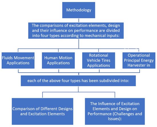
2. Methodologure 1.
y
In the present review, the comparisons of excitation elements, design and their influence on performance are divided into four types according to mechanical inputs: fluids
(air, water) movement, human motion, rotational vehicle tires, and other rotational operational principals. For each one, mechanical inputs, excitation type, design, methodology,
and wiring have been characterised and thoroughly reviewed. The type of excitation has
been subdivided according to excitation elements, such as mass, gear, magnetic, spring,
centrifugal, gravity and impact forces. Each group may contain one or more of the excitation elements to conclude which group has the maximum influence on rotational piezoelectric energy harvesting enhancement. The design comparison also discusses the piezoelectric rotation, which may affect the type of wiring for output power transfer. The fixed
piezoelectric cantilever uses direct wiring, while a rotating one requires either a slip ring
or Arduino and Bluetooth for output power transfer. For each of the following section. At
the end of each section, a summary table was made by the author with full detail and
calculated power density for related previous works, as in Tables 1–4. A plot has also been
made by the authors for all the designs, due to rpm and output power density, to give a
clear idea about the best excitation elements and which one has the highest power density,
and as in Figures 5, 9, 13, and 18, respectively. Figure 1 show the methodology schematic
diagram.
Figure 1. Methodology schematic diagram
3. Fluids Movement Applications
3.1. Comparison of Different Designs and Excitation Elements
Firstly, the studies that use air (wind) as a mechanical input source for RPZTEH have been reported. Using air only as an excitation element, Stamatellou & Kalfas [13][29] utilised air swirled to create a turbulent flow field and harvest energy, as shown in Figure 2a. Similarly, Febbo et al. [14][55] performed a novel design alternative to a simple PZT beam that fixed the beam to a hub, by utilising a beam, spring, gravity, centrifugal forces, and two masses as excitation elements, as shown in Figure 2b. The same authors enhanced their model [15][74] by adding a single side spring stop, in addition to the two-flexible beam, and the spring that joined the two dense masses, as shown in Figure 2c.

Figure 2. (a) Simultaneous measurement of the pressure and piezoelectric film output voltage [13][29]; (b) View of rotating energy harvesting system [14][55]; (c) View of enhanced energy harvester [15][74].
However, Y. Yang et al. [16][30] have used impact-induced resonant to have piezoelectric beam effective excitation vibration mode. The harvester-based knowledge designed is that; an impact could excite resonance beneath any operating conditions. A configuration has been made of twelve PZT beams and a seven ball, as shown in Figure 3a. Alternatively, Zhao et al. [17][75] presented an innovative method for RPZTEH with wind and use mechanisms of force amplification and magnetic coupling as excitation only. By arranging the magnetic in a symmetrical opposite way, they maximised the effective force and significantly reduced the resistance torque, as in Figure 3b. Additionally, a built-in wind generator has been designed to supply sensor nodes with power in hard reach or remote locations from low wind speed by Karami et al. [18][52] using magnetic only as excitation. Two configurations have been made: a tangential and a radial one, as in Figure 3c.

Figure 3. (a) Piezoelectric windmill diagram shows piezoelectric bimorphs arrangement [16][30]; (b) Schematic illustration and working mechanism of the investigated Magnetically Coupled Piezoelectric Wind Energy Harvester (MPWEH). The symmetrical opposite magnetic arrangements [17][75]; (c) Prototypes of nonlinear wind harvester: configuration of tangential design and configuration of radial design [18][52].
Furthermore, a piezoelectric energy harvester and hydro-electromagnetic have been designed to give power to the smart type of water meter system using water flow and magnetic force for excitation by Cho et al. [19][37]. A stainless-steel turn-buckle water wheel of 90 mm diameter and two magnets was proposed in this work, as shown in Figure 4a. Conversely, in the An et al. study, a novel vortex-induced PZT energy converter (VIPEC) is proposed to harvest the ocean’s kinetic energy in the underwater environment [20][32]. The harvester consists of a storage circuit, PZT patches, cylinder, and a pivoted plate attached to its tail, as shown in Figure 4b.
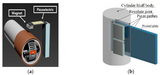
Figure 4. (a) Pipe-flow energy harvester system using magnets and with no contact [19][37]; (b) A general view for a vortex-induced piezoelectric energy harvester [20][32].
3.2. The Influence of Excitation Elements and Design on Performance (Challenges and Issues)
As shown in Table 1, a comparison has been made between variable factors, divided into input, output, and comments. In general frequency (rpm), Piezoelectric size, dimension, and material type, resistance, and whether the Piezoelectric rotate or not, using a slip ring or not, all these elements affect piezoelectric energy harvesting output power, as shown in Table 1. Output power and power density are also included in this table. Although, excitation elements affect the design, however, as shown in Table 1, for the same excitation elements, the output power density is different depending on the design. The materials used in the RPZTEH were mainly PZT; however some researchers used PVDF and PZT composite.
| Number | Ref. | Input | Output | Comments | ||||||||||
|---|---|---|---|---|---|---|---|---|---|---|---|---|---|---|
| Excitation Elements | Volume (mm3) | Piezo Dimension (mm) | Polarisation Mode | Material Type Use | rpm | Frequency (Hz) | Optimal Resistance (Ω) | Power (µW) | Power Density (µW/mm3) | Mechanical Power Source | PZT Rotate or Not | Wiring | ||
| 1 | [13][29] | air swirler | 96.2 | 37 × 13 × 0.2 | / | PVDF | 300 | 6 | 47 | 3 | 0.03 | Air | Not | Normal wiring |
| 2 | [14][55] | M + Sp + Gr | 328 | 50.8 × 25.4 × 0.254 | d31 | PZT 5A | 150 | 13.1 | 10 k | 105 | 0.32 | Air | Yes | storage rotates with the system |
| 3 | [15][74] | Sp + M + Gr | 326.5 | 50.8 × 25.4 × 0.254 | d31 | QP16N | 150 | 2.5 | 5 × 10⁵ | 845 | 2.588 | Air | Yes | Bluetooth |
| 4 | [16][30] | imp | 470 | (47 × 20 × 0.5) | / | PZT | 200 | 3.33 | 20 k | 613 | 1.3 | Air | Yes | supercapacitor |
| 5 | [21][66] | M + Mg | 4.26 | 16 × 3.5 × 0.076 | / | PZT-bimorph | 751 | 12.5 | 200 k | 0.25 | 0.06 | Air | Not | fixed piezo |
| 6 | [22][65] | M + Mg | 115 | 31.8 × 7.12 × 0.508 | d31 | Q220-A4–303YB | 3696 | 61.6 | 3300 | / | 0.59 | Air | Not | the application within the rotation area |
| 7 | [17][75] | Mg | 400 | 40 × 10 × 1 | / | (PZT-5H) | 546 | 9.1 | 3 × 10⁵ | 1320 | 3.3 | Air | Not | / |
| 8 | [23][54] | Mg | 3360 | 70 × 32 × 1.5 | / | PZT layer | 600 | 10 | 8000 k | 16000 | 4.76 | Air | Not | Normal wiring |
| 9 | [18][52] | Mg | 323 | (50 × 12.7 × 0.127) × 4 | d31 | PZT-5A | 200 | 16 | 247 k | 5000 | 15.5 | Air | Not | Normal wiring |
| 10 | [24][76] | M + Gr + Mg | 776 | 40.2 × 25.4 × 0.76 | d31 | (PPA-2011) | 30 | 34 | 25 k | 2200 | 2.835 | Air | Yes | slip ring |
| 11 | [19][37] | Mg | 315 | 45 × 35 × 0.2 | d31 | PZT-ceramic | 120 | / | 10 k | 196 | 0.6222 | Wat | Not | / |
| 12 | [20][32] | vortex-induced | / | / | d31 | PZT | / | 16.49 | 1 × 10⁵ | / | 0.035 1E + 09 | Wat | Not | / |
| 13 | [25][77] | Water flow + slide-crank | 166.4 | 52 × 16 × 0.2 | / | ionic polymer metal composites | 372.4 | 1 | 50 | 1 × 10⁹ | Wat | Not | / | |
| M for mass, Mg for magnetic, Gr for gravity, Sp for spring, Wat for water, air for air, imp for impact force, and /for no information from the authors. | ||||||||||||||
In Figure 5, all the above studies have been plotted with rpm and output power density to have a clear idea about the best excitation elements with the highest power density. As shown in the figure, the studies that use magnetic force as an excitation element get an excellent output power density [18][23][52,54]. Both of them use only magnets for excitation and able to harvest excellent output power.
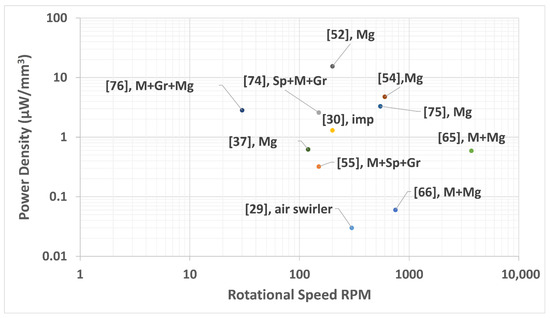
Figure 5. Power density comparison for different studies on rotational piezoelectric energy harvesting for fluid input mechanical power source with different excitation elements and as follows: M for Mass, Mg for magnetic, Gr for gravity, Sp for spring, and air swirler for air swirler.
4. Human Motion Applications
4.1. Comparison of Different Designs and Excitation Elements
One of the challenges of human motion energy harvesting is random excitation and low frequency. Pillatsch et al. [26][64] used a successful frequency up-conversion strategy: introducing an inertial device containing PZT beam buckling principle using the magnetic coupling of two permanent magnets and a rotating mass in half disk shape with a gravitational force as excitation elements, as shown in Figure 6a.

Figure 6. (a) Harvester prototype isometric view and section view [26][64]. (b) Diagram structure of the wrist driven rotational energy harvester using magnetically plucked PZT [27][78]; (c) The energy harvester diagram [12][72].
A novel wearable energy harvester that converts the low frequency of human limb into high frequency has been proposed in this study by Li, Keli, et al. [28][25]. Micromachined nickel cantilever and NdFeB magnet were glued and fixed on a polydimethylsiloxane (PDMS) film, as shown in Figure 7a.

Figure 7. (a) Photos show wearable applications where two flexible harvesters are fixed on a human elbow and knee with Close views [28][25]; (b) Piezoelectric knee-joint energy harvester with frequency up-conversion by magnetic plucking [29][48]. However, in this study, Mohamad Hanif et al. [30][49] was utilised only the mass concept for excitation. They have designed a prototype consists of PZT cantilever, a rotor with a pole on it for PZT plucking, and aluminium proof mass, as in Figure 8a.
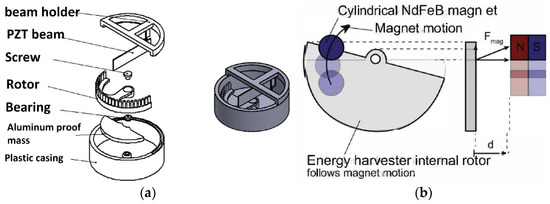
Figure 8. (a) Exploded view of the rotational motion energy harvester device [30][49]; (b) The harvester rotor design with the motion of magnetic and internal rotor [31][47].
4.2. The Influence of Excitation Elements and Design on Performance (Challenges and Issues)
Table 2 summarises different variables, divided into input, output, and comments. Excitation elements greatly affect the shape of the design and make it suitable for certain applications and help harvest sufficient output power.
| INPUT | Output | Comments | ||||||||||||
|---|---|---|---|---|---|---|---|---|---|---|---|---|---|---|
| © | Ref. | Excitation Elements | Volume (mm3) | Piezo Dimension (mm) | Polarisation Mode | Material Type Use | rpm | Frequency (Hz) | Optimal Resistance (Ω) | Power (µW) | Power Density (µW/mm3) | Mechanical Power Source | PZT Rotate or Not | Wiring |
| 1 | [26][64] | M + Mg + Gr | 1850 | / | / | PZT | 120 | 4 | 150 k | 43 | 0.0232 | HM | Yes | / |
| 2 | [27][78] | M + Mg | 18.06 | 12 × 3.5 × 0.43 | / | piezo-electric M1100 ceramic | 75 | 1.25 | 95 k | 6.25 | 0.3461 | HM | Not | Normal wiring |
| 3 | [32][24] | M + Mg | 73.1 | 42 × 7.1 × 0.245 | / | PZT-5H | 60 | 1 | 80 k | 140 | 1.92 | HM | Yes | Normal wiring |
| 4 | [12][72] | M + Mg | 1012 | 33 × 14 × 0.73 | d31 | PZT5A | 1212 | 20.2 | 75 | 4230 | 4.18 | HM | Yes | slip ring |
| 5 | [33][79] | Mg | 103.8 | 6.4 × 31.8 × 0.51 | d31 | PZT-5A4E | 100 | 1.667 | / | 234.5 | 2.259 | HM | Not | Normal wiring |
| 6 | [28][25] | Mg | 1.2 | 5 × 4 × 0.06 | d31 | PZT | 300 | 5 | 40 k | 3.5 | 2.92 | HM | Yes | / |
| 7 | [29][48] | Mg | 1471 | 38.1 × 12.7 × 0.38 | / | PZT bimorph 5H | 54 | 0.9 | 15 k | 5800 | 3.94 | HM | Yes | / |
| 8 | [30][49] | M | 200 | 40 × 10 × 0.5 | / | PZT5H) | 1080 | 18 | 12 k | 1300 | 6.5 | HM | Yes | Normal wiring |
| 9 | [31][47] | Mg + Gr | 7.22 | 19.5 × 1 × 0.37 | PZT bimorph | 1500 | 25 | 151 k | 100 | 13.9 | HM | Yes | Normal wiring | |
| M for mass, Mg for magnetic, Gr for gravity, HM for human motion, and/for no information from the authors. | ||||||||||||||
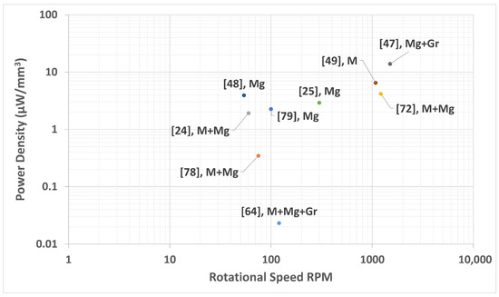
Figure 9. Rotational piezoelectric energy harvesting for human motion mechanical input with excitation elements and as follow: M for Mass, Mg for magnetic, and Gr for gravity.
5. Rotational Vehicle Tires Applications
5.1. Comparison of Different Designs and Excitation Elements
Xie, Kwuimy et al. [34][19] presented a rotational energy harvester using a PZT bistable buckled beam, with a rotating disk in low rotational speed, and magnetic force only as excitation as in Figure 10a. Furthermore, Fu & Yeatman [35][20] also used magnetic coupling as excitation for frequency up-conversion in low-frequency rotational energy harvesting. A prototype consists of a piezoelectric cantilever harvester with a magnetic on its tip and a rotating magnetic on the rotating host, as shown in Figure 10b.
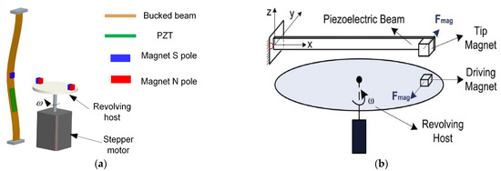
Figure 10. (a) Energy harvester design [34][19]; (b) Energy harvester diagram: Outline of magnetic coupling and parameters of structure [35][20].
Along with, Zhang et al. 2016 [36][42], presented an energy harvester using magnets, mass, and gravity force for excitation. The prototype consisted of; aluminium beam, PZT adhesive on it, two magnets, and an adjusting pole to change the distance between them, as in Figure 11a. Similarly, mass, magnetic, but with centrifugal force, has been used as the design excitation elements by Shange et al. 2018 [37][63]. A prototype consists of two magnetic masses with the same polarities and a cantilever beam with piezoelectric attached to it, which is applied on a rotating energy harvester tire, as in Figure 11b.
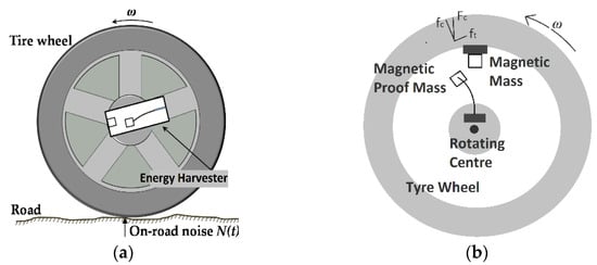
Figure 11. (a) Energy harvester fixed to the wheel centre [36][42]; (b) Rotating tire energy harvester model, with real one photo [37][63].
Hence, Guan & Lia [38][43] have used mass, spring, and gravity forces for excitation. The prototype is made of; piezoelectric mounted on a beam and fixed near the edge of a rotating frame with mass at its end, as in Figure 12.
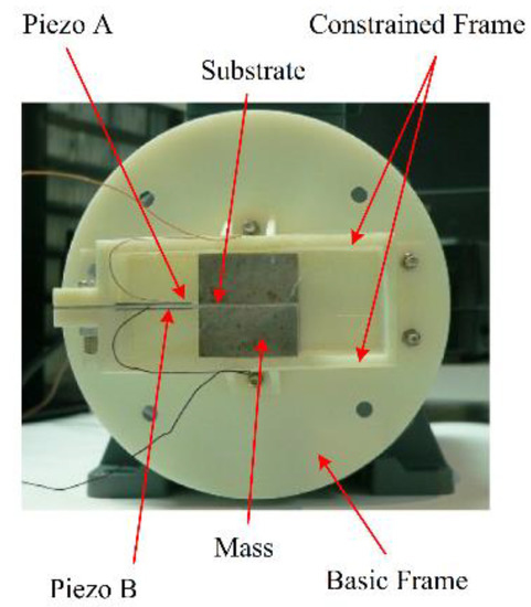
Figure 12. The prototype of the piezoelectric harvester structure fixes on the frame [38][43].
5.2. The Influence of Excitation Elements and Design on Performance (Challenges and Issues)
As shown in Table 3, a comparison has been made between variable factors, divided into input, output, and comments. In general frequency (rpm), PZT size, dimension, and material type, resistance, and whether the PZT rotate or not, using a slip ring or not, all these elements that affect on piezoelectric energy harvesting output power has been reported in Table 1, also, both output power and power density have been reported as well in this table.
| Input | Output | Comments | ||||||||||||
|---|---|---|---|---|---|---|---|---|---|---|---|---|---|---|
| Number | Ref. | Excitation Elements | Volume (mm3) | Piezo Dimension (mm) | Polarisation Mode | Material Type Use | rpm | Frequency (Hz) | Optimal Resistance (Ω) | Power (µW) | power Density (µW/mm3) | Mechanical Power Source | PZT Rotate or No | Wiring |
| 1 | [34][19] | Mg | 42.2 | 22 × 8 × 0.24 | / | PZT-5H | 840 | 14 | 110 k | 65.4 | 1.55 | VT | No | Direct wiring |
| 2 | [35][20] | Mg | 3.98 | 26.5 × 1.5 × 0.1 | / | / | 2100 | 300 | / | 20 | 5.03 | VT | No | Direct wiring |
| 3 | [39][80] | Mg + Cn | 64.5 | 25.4 × 12.7 × 0.2 | / | PZT 5A | 330 | 5.5 | / | 3.5 | 0.05 | VT | Yes | / |
| 4 | [4] | Mg + Cn | 30 | 25 × 12 × 0.1 | D31- | PVDF | 965 | 16 | 600 k | 36 | 1.2 | VT | Yes | Slip ring |
| 5 | [36][42] | M + Mg + Gr | 22.9 | 22.9 × 10 × 0.1 | / | PZT-ceramic | 552 | 9.2 | 252 k | 12 | 0.52 | VT | / | / |
| 6 | [37][63] | M + Mg + Cn | 21.3 | 22.9 × 9.3 × 0.1 | / | / | 365 | 6.08 | 150 k | 240 | 11.3 | VT | Yes | / |
| 7 | [40][58] | Cn | 80 | 25 × 6.4 × 0.5 | d31 | PZT | 972 | 16.2 | / | 123 | 1.54 | VT | Yes | slip ring |
| 8 | [41][59] | M + Cn | 130 | 41.3 × 6.3 × 0.5 | / | PZT | 792 | 13.2 | / | 700 | 5.38 | VT | Yes | slip ring |
| 9 | [42][44] | Cn + M | 24.5 | 70 × 5 × 0.07 | d33 | PZT-5H | 952 | 15.9 | 1000 k | 500 | 20.4 | VT | Yes | slip ring |
| 10 | [38][43] | M + Sp + Gr | 380 | 28.5 × 50 × 0.267 | / | PSI-5A4E | 810 | 13.5 | / | 825 | 2.17 | VT | Yes | slip ring |
| 11 | [43][81] | M + Sp + Cn | 66 | 22 × 6 × 0.5 | D31 | PVDF | 700 | 11.7 | 3300 k | 140 | 2.12 | VT | Yes | slip ring |
| 12 | [44][82] | M + Gr + Cn | 600 | 150 × 20 × 0.2 | / | PVDF | 504 | / | 2 × 10⁵ | 1003 | 1.6717 | VT | Yes | slip ring |
| 13 | [45][83] | M + Gr + Cn | 424.2 | 101 × 20 × 0.21 | / | PZT (MFC) | 1008 | 16.79 | 2 × 10⁵ | 6280 | 14.804 | VT | Yes | Sd card |
| 14 | [46][84] | M + Gr + Cn | 612 | 51 × 20 × 0.6 | d31 | PZT-5H | 1300 | 21.67 | 40 k | 16,520 | 26.993 | VT | Yes | slip ring |
| M for mass, Mg for magnetic, Cn for centrifugal, Gr for gravity, Sp for spring, VT for vehicle tires, and/for no information from the authors. | ||||||||||||||
Figure 13 compares all these designs according to rpm and the output power density to have a clear idea about the best excitation elements. As shown in the Figure, almost 78% of the reported studies have used centrifugal force for excitation.
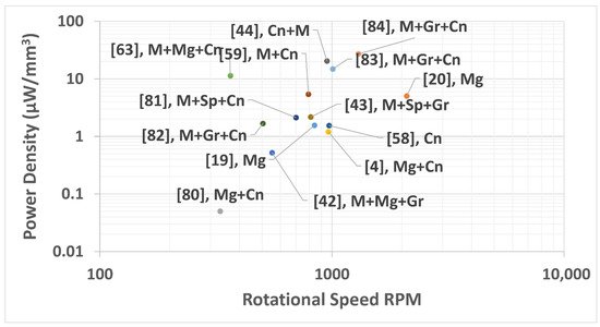
Figure 13. Rotational piezoelectric energy harvesting for vehicle tires mechanical input with excitation elements and as follow: M for mass, Mg for magnetic, Cn for centrifugal, Gr for gravity, and Sp for spring.
6. Conclusions
In general, many essential factors influence the rotational piezoelectric harvester output power, which made a wide range of output power from nano to milliWatts. Design with a fixed piezoelectric cantilever is more favourable for future work. In this case, normal wiring can be used for the output power transfer, without a slip ring or any extra component that makes the design less compact. Generally, for most rotational piezoelectric energy harvesting applications, it can be said that the magnetic force had a good influence on optimising output power considering the pole direction and the number of magnets. The studies revealed that the design of a small compact prototype with a fixed piezoelectric to avoid slip ring and using magnetic, gravity, and centrifugal forces had a good influence on output power optimisation. Future work should also focus on using gear for frequency up-conversion to enhance output power density and keep the design simple and compact.
