Carbon capture use and storage (CCUS) is considered an effective mitigation strategy to reduce the most challenging emissions from heavy industries and gas processing. The safe transport of carbon dioxide via pipelines is an important aspect for developing large-scale Carbon Capture and Storage projects. Dispersion modeling for heavy gas such as carbon dioxide is considerably different from natural gas. The set up for modeling simulations is more challenging than conventional natural gas pipeline for several reasons, such as the differences in thermodynamics that must be considered. Moreover, when the carbon dioxide is transported in dense or liquid phase, the rapid phase changing, and possible consequent formation of solids should be considered. Finally, the equation of state required for accurate prediction of parameters is generally different than the ones applicable for natural gas.
- carbon dioxide
- CO2 transport
- CO2 pipeline
- experimental modeling
- dispersion modeling
1. Risk Analysis for CO2 Pipelines
The risk management strategy should be based on relevant industry good practice which focuses on inherent safety and the prevention of incidents with the potential to endanger people, the environment, or properties. Compared to natural gas, there are less companies with relevant experience in full-scale CCS projects development and few projects has been completed so far [1]. Thus, great care should be taken during hazard identification and management when dealing with CCS projects. According to DNV-GL [2], carbon dioxide pipelines should be designed with acceptable risk. The growing interests from energy companies in CCS will lead to the development of new generation CO
2 pipeline systems that will require thorough risk assessments and to be design within acceptable risk levels as required by DNV-GL [2]. Since the fluid is usually transported in dense phase, there is the potential for large inventories of CO
2 being released in the atmosphere which could reach populated areas with hazardous concentrations. According to ISO 13623 [3] and DNV-GL-RP-F104 [2], CO
2
2
2. Experimental Release Tests for CO2-Rich Mixtures
2.1. Joint Industry Projects and Research Projects
Table 1
Table 1.
2
| JIP/RP Name | Years/Period | Scale | Objectives and Scope |
|---|
| CO2SAFEARREST | 2016–2019 | Full-scale | Burst tests research program. Two full-scale tests with buried pipeline (CO2-N2 mixture), 24 inches. |
| COSHER | 2011–2015 | Large-Scale | Obtain data to support the development of models to determine safety zones/consequence distances. |
| CO2PIPETRANS | 2009–2015 | Medium-Scale Large-Scale |
Fill the knowledge gap identified in the DNV-RP-J202. Results of the project were included in DNVGL-RP-F104 (2017). |
| COOLTRANS | 2011–2015 | Large-Scale | Identify and propose solutions to key issues relating to the safe routing, design, construction and operation of onshore CO2 pipelines in the UK. |
| CO2PIPEHAZ | 2009–2013 | Small Scale Large-Scale |
Improve the understanding of the hazards represented by CO2 releases. |
| CO2QUEST | 2013–2016 | Small Scale Medium-Scale |
Study the impact of the quality of CO2 on storage and transport. |
| CATO | 2004–2008 2010–2014 2015-ongoing |
N/A | A national program, which includes complete studies in all aspects of CCS. |
| CO2EUROPIPE | 2009–2011 | N/A | Outline guidance to elements of the European plan to develop large-scale EU CO2 infrastructure. |
| CO2RISKMAN | 2010–2013 | N/A | Development of industry guideline to assist the designer and projects on the emerging CCS industry. Potential hazards associated with handling CCS CO2 streams are discussed. |
2.2 Experimental Testing
2
Figure 1
2
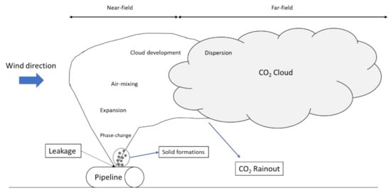
Figure 1.
2
Since near-field modeling can strongly impact the far-field modeling and the definition of safety distances, particular attention should be reserved to these aspects. Pursell [4] presented some results from laboratory scale release tests performed in Health and Safety Laboratory (UK). The experiments were performed both for liquid and gas phase of CO
2
2
2
Useful data were obtained by analyzing the images, such as the length of the expansion zone and the effective diameter of the jet at the point where it reaches atmospheric pressure. Since it is not easy to define the location of the shock front in liquid releases, the effective diameter could be useful for dispersion calculations (assuming a gas phase equivalent diameter) since it is often used to define the size of the pseudo-source. Results showed that liquid releases led to an effective diameter up to 30% larger than the corresponding gas phase in the diameter of the analyzed orifice. Guo et al. [5] studied the near-field characteristics and dispersion behaviour of supercritical [6], gaseous, and dense-phase CO
2
2
2 can impact the properties and the shape of the cloud. Based on the experimental data performed by Guo et al. [5], the development of the visible cloud can be divided into three stages: a “rapid expansion”, a “metastable stage”, and a “slow attenuation
stage
2 leakage has been reported by Fan et al. [7]. The pressure and temperature conditions analyzed varied from 81 to 110 bar and 34.9 °C to 100.9 °C. The authors noted how the mass flow rate decreases with the increase of upstream temperature and length-diameter ratio and increases with the increase of upstream pressure. However, the effect of upstream temperature variation (at approx. 100 bar) on the jet structure was not so evident in the range between 37.6 °C and 40.1 °C.
An experiment with various measurement methods was developed by Teng et al. [8] to carry out controllable CO
2
2
2 leakage, dry ice particles with size between 1 and 3 μm can be formed. The initial temperature shows limited impact on the size of dry ice particles, while a wider size distribution can be addressed to a higher initial pressure. Li et al. [9] developed a reduced scale facility with dry super-critical CO
2
Ahmad [10] reported the results based on COSHER JIP; a large-scale rupture test was conducted on a loop test built in Spadeadam (UK). A 219 mm diameter pipeline buried underground filled with dense phase CO
2
2
2 dispersion in the atmosphere [11][12]. The outer diameter of the test section was a steel pipe 610 mm, 85 m long, connected to approx. 120 m long reservoirs at both ends. A mixture of 91% CO
2
2
2
In the work of Allason et al. [13], the COOLTRANS experimental campaign has been described and some considerations are reported. During the program, vertical pipe venting and puncture tests have been performed.
2
2
2
2
2
2
2
3. Modeling CO2 Accidental Releases
Modeling a release of a CO2
pipeline requires the assessment of some important aspects, such as transient conditions, multi-phase jet, as well as the dispersion behavior. A rapid pressure drop will follow the release of CO2 from a pipeline; the pressure and temperature reduction a phase transition from liquid-vapor is expected. Moreover, for lower temperature the formation of solids is also a possibility. The phase transition can impact the flow conditions within the pipeline and the properties of the fluid. The precise simulation of transient depressurization, with regards of flow rate and thermodynamic properties of CO2
during the release, will impact the accuracy of the cloud dispersion prediction. Specific focus must be reserved to phase transition and density prediction of the CO2 during transient operations in order to better predict solid formations. Release and dispersion studies are required for risk evaluations. Three main steps can be identified in dispersion modeling:
during transient operations in order to better predict solid formations. Release and dispersion studies are required for risk evaluations. Three main steps can be identified in dispersion modeling:-
Outflow calculations
-
Expansion to atmospheric pressure (near-field)
-
Far-field dispersion
- OpenFOAM
- FLUIDYN PANACHE
-
Outflow calculations
-
Expansion to atmospheric pressure (near-field)
-
Far-field dispersion
2
releases can be highlighted, which may constitute a limitation in developing accurate simulations, in particular: the selection of an Equation of State for an accurate description of the thermodynamic properties throughout the release process, the modeling of phase changing (from dense phase to gaseous), prediction of solid phase formation, the validity of homogeneous equilibrium (HEM) assumption. Another aspect to be considered is the very limited experience in CO2
pipeline modeling; for this reason, most codes and simplified models need to be assessed and validated with experimental tests data. Two main approaches are available to model an accidental release:-
Simplified models
- CFD models
The simplified models usually require very low CPU usage compared to CFD models; hence they are faster and optimized for risk analysis. However, a simplified model, such as an integral model, is based on several assumptions and simplifications to the physics of the phenomena; for these reasons they need to be extensively validated with real case data, experimental tests. CFD models can provide a very detailed description of the physics and the behavior of a CO
2
release; this kind of approach is required when a complex topography, specific environment conditions or presence of buildings or other obstructions in the nearby area. These models require high experience and specific knowledge from the user to be set up and executed, compared to simplified integral models. Moreover, the uncertainties specific to CO
2
related to limited experience and optimization often require custom-made inputs and user-defined functions to be implemented in commercial CFD software.
3.1. Simplified Models
The most commonly available simplified models are the integral models implemented in existing commercially available software. Since most risks in the oil and gas industry come from flammable liquids or gases, none of them was originally designed to take into account inert gas such as CO2
. The main models identified are:-
FRED
-
PHAST
-
ALOHA
-
EFFECTS
3.2. CFD Models
Specific attention has been reserved to commercially available software and their capability to handle CO2
releases. The main CFD codes identified are:-
ANSYS FLUENT
-
ANSYS-CFX
-
FLACS
4. Conclusions
It is suggested to approach the near-field modeling and the far-field modeling in two separate ways. The near-field modeling of a CO2
release requires specific knowledge of the gas-dynamic phenomena in sonic and supersonic transitions, namely Mach number, wave motion, and sonic speed. The CFD code that performed better when compared to experimental tests was ANSYS-CFX. Even though simulating the entire phase transition is theoretically feasible, in practice, it is hard to simulate with a single CFD code, with issues mainly related to time steps and grid refinement. The unstructured hexahedrons mesh available by default in the ANSYS packages seems more suitable for specific cases when obstacles and hilly terrain need to be modeled. Finally, the terrain effects can be dominant for CO2
dispersion; for this reason, CFD modeling, especially in the vicinity of depression or large differences in terrain heights close to a CO2
pipeline route, can overcome the limitations of simple models such as integral models.