Your browser does not fully support modern features. Please upgrade for a smoother experience.
Please note this is a comparison between Version 1 by David Puma and Version 2 by Rita Xu.
Extended-range electric vehicles (EREVs), commonly known as series hybrid electric vehicles (Series-HEV), have better autonomy than electric vehicles (EV) without range extenders (REs). EREVs can go from one city to another or make long journeys in general.
- extended range electric vehicle
- technologies
- optimization methods
- EREV key components
1. Introduction
Extended-range electric vehicles (EREVs), commonly known as series hybrid electric vehicles (Series-HEV), have better autonomy than electric vehicles (EV) without range extenders (REs). EREVs can go from one city to another or make long journeys in general. In recent years, EREVs have attracted considerable attention because of the necessity to improve autonomy using new and different technologies to generate extra energy for EVs. Today, fossil fuels meet the needs of the transportation sector to a significant extent, but bring on various adverse effects, such as air pollution, noise, and global warming. Compared to internal combustion engine vehicles (ICEVs), EREVs reduce emissions and are considered a favorable alternative [1][2][1,2]. EREVs, compared with EV, not only have the advantage of “zero fuel consumption and zero emissions”; they also effectively solve the problem of having an inadequate driving range due to power storage limitations in batteries [3].
2. Extended Range Electric Vehicle Technology
A range extender (RE) is a small electricity generator (APU) which operates when needed as a solution to increase autonomy in EVs. The main components of the RE are the generator and internal or external combustion engine; the internal or external combustion engine is coupled to the generator in a series configuration. The primary function of the RE for an EV is to extend the vehicle’s mileage. Operation of the range extender is initiated if the SOC (state of charge) of the EVs battery drops below a specified level. In this situation, the engine provides electricity by recharging the battery or directly driving the EV during travel and continues the vehicle’s operation [4]. The difference in a plug-in hybrid electric vehicle (PHEV) is that the electric motor always propels the wheels. The engine acts as a generator to recharge the vehicle’s battery when it depletes or as it propels the vehicle [5]. A series configuration is used as the main system, which is considered an APU. The system is connected to several subsystems, such as the generator, battery, electronic management system, and electric motor. The electric motor converts electrical energy from the battery to mechanical power. It propels the wheels while the APU generates electric energy to recharge the battery. Finally, the electronic management system controls all the systems for optimal functioning. The EREV has two operation modes: pure electric vehicle and extended-range mode. If the distance is short, the vehicle operates in pure electric vehicle mode without the RE. If the distance is long, the vehicle operates in extended-range electric vehicle mode.
The RE is off as long as there is sufficient energy in the battery for purely electric driving, and activated whenever the SOC drops below a certain level. The RE works until the desired SOC is achieved. The battery power manager gives this function. Figure 1 shows an EREV and energy flow configuration: (a) charge sustaining period and (b) depletion period. There are many technical and social challenges ahead for EVs coming up against the conventional ICEVs. Range anxiety is the most challenging problem facing EV drivers due to their shorter driving ranges compared to ICEVs. Range anxiety stems from the limited energy density in the current batteries (0.565 MJ/kg for Li-ion battery), which is very low as compared to fossil fuel (43.48 MJ/kg) [6].
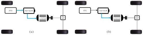
Figure 1.
Configuration of an EREV and energy flow: (
a
) charge sustaining period; (
b
) depleting period.
2.1. Technological Classification of EREV
The electric propulsion system is the heart of an EREV. It consists of the motor drive, a transmission (optional) device, and wheels. There are three kinds of electric motors: direct or alternating current and in-wheel motors (also called wheel motors). The primary requirements of the EREV motor are summarized as follows:
-
High instant power and high power density.
-
High torque at low speeds for starting and climbing, and high power at high speeds for cruising.
-
An extensive speed range including constant-torque and constant-power regions. In this case, the APU, when it is on, needs to operate in the same regions.
-
Fast torque response.
-
High efficiency over a large speed and torque ranges.
-
High reliability and robustness for various vehicle operating conditions.
-
Reasonable cost.
2.1.1. Internal Combustion Engine Extended Range (ICE-ER)
The range extender comprises a fuel tank, an internal combustion engine, and a permanent magnet synchronous generator [3][6][7][8][9][10][11][12][13][14][15][16][17][18][19][20][21][22][23][24][25][26][27][28][29][30][31][32][33][34][3,6,7,8,9,10,11,12,13,14,15,16,17,18,19,20,21,22,23,24,25,26,27,28,29,30,31,32,33,34], as shown in Figure 2. The structure is mechanically decoupled between the RE and the wheels of the EV. This configuration leads to a strong point whereby the output characteristics of the RE are not related to the vehicle’s traction performance, and the output power only needs to meet the driving requirements. Therefore, one of the main objectives is to keep the RE operating in the high-efficiency region. The engine and the generator should be matched to achieve this common operating region [8]. As another solution, several studies have focused on energy harvesting using other types of fuels, such as natural gas [35] or diesel [36][37][36,37], to reduce pollution levels.
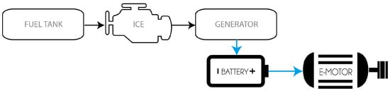
Figure 2.
A diagram of the configuration of ICE-ER.
2.1.2. Regenerative Shock Absorber Extended Range (RSA-ER)
The shock absorber is a crucial component of the vehicle suspension and is combined with the suspension spring to filter vibrations when driving on rough roads. Typically, energy from vibrational sources is dissipated through hydraulic friction and heat via shock absorbers [38][38][38,38]. Currently, there are three categories for RSAs. The first type directly uses an electromagnetic method to generate electric power. The schemes of operation can be linear or rotary [39]. A linear electromagnetic RSA converts the kinetic energy of vertical oscillations into electricity by electromagnetic induction.
The second is the hydraulic RSA. This RSA can harvest energy by employing oscillatory motion to drive the power generator. Some studies reformed the existing hydraulic shock absorber and utilized the oil in the shock absorber to flow into a parallel oil circuit. They usually used the flowing fluid to drive a hydraulic motor connected in parallel to a DC/AC generator [40].
The third category is the mechanical RSA, which was developed quickly because of its greater efficiency and average power [38]. The general architecture of said RSA using supercapacitors, which are applied to extend the battery endurance, has four main parts: (1) the suspension vibration input module, (2) the transmission module, (3) the generator module, and (4) the power storage module, as shown in Figure 3.
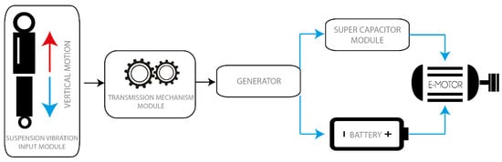
Figure 3.
A diagram of the configuration of an RSA-ER.
2.1.3. Regenerative Braking Extended Range RB-ER
The EV’s motor can work as a generator under deceleration procedures, charging the battery and exerting regenerative braking torque on the axle simultaneously, as shown in Figure 4. A regenerative braking system (RBS) can capture the kinetic energy of an electric vehicle during the deceleration process, thereby improving the EV’s energy efficiency. For an EV, friction and regenerative brakes generate brake torque, either separately or together [41]. In addition, the use of an adequate control strategy helps to reduce the loss rate; for example, the revised regenerative braking control strategy (RRBCS) can reduce inefficiency at the expense of slight braking energy recovery loss. Thus it positively affects prolonging the battery’s life while ensuring braking safety and maximal recovery energy [42].
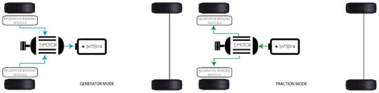
Figure 4.
The configuration of an RB-ER. Energy flow: left generator mode and right traction mode.
An EV with automatic mechanical transmission (AMT) has higher transmission efficiency because it uses a composite braking process. The braking force of the motor varies according to the transmission gears at the same speed. Therefore, when the vehicle is braking, the transmission gear can be shifted reasonably according to the vehicle’s condition. This mechanism improves the EV economy, since it allows the motor to work efficiently while recovering the braking energy to the maximum extent. An appropriate strategy can effectively improve the energy recovery rate and ensure braking safety and stability [43].
2.1.4. Fuel Cell Extended Range (FC-ER)
Fuel cells (FC) are electrochemical energy conversion devices that convert chemical energy directly into electrical energy and heat [44]. The electrochemical transformation is a chemical reaction of oxidant and reductant to produce electricity and water in stack output [45].
An anode, a cathode, and an electrolyte are the main components of an FC; water and electrical energy are the products. In the process, the anode supplies hydrogen, and the cathode terminal supplies oxygen [46]. During the reaction, hydrogen decomposes into positive protons and negative ions on the anode side. The resulting positive particles reach the cathode tip through the electrolyte, allowing only the positively charged particles to pass. The electrons, the negative ions at the end of the anode, tend to reunite with the positively charged particles and pass to the cathode side through an external circuit. This electron flow in the external circuit generates electricity. The electrons passing to the cathode side combine with positively charged particles and oxygen to produce pure water and heat, as shown in Figure 5 [1][47][48][49][50][51][52][53][1,47,48,49,50,51,52,53].
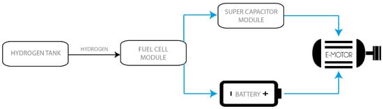
Figure 5.
A diagram of the configuration of FC-ER.
2.1.5. Micro Gas Turbine Extended Range (MGT-ER)
Microturbines (MGT) are small gas turbines with output power levels of 30 to 500 kW [54]. A MGT mainly consists of a single-stage radial compressor, a radial turbine section, and a recuperator. They usually use foil bearings (air bearings). The typical cycle of an MGT consists of four processes:
-
A radial compressor compresses the inlet air.
-
Air is pre-heated in the recuperator using heat from the turbine exhaust.
-
Heated air from the recuperator is mixed with fuel in the combustion chamber and burned.
-
Hot gas expands in turbine stages, and the gas’s energy is converted into mechanical energy to drive the air-compressor and the drive equipment (usually generator).
Automakers claim that the gas turbine is the most efficient solution that is on its way. In particular, MGT can be an alternative to the ICE as a RE for EVs. The MGT produces less raw exhaust gaseous emissions, such as hydrocarbons and carbon monoxide, and has more static applications compared to the ICE. In addition, any MGT is lighter than the equivalent ICE, and it provides a potential reduction in the level of carbon dioxide produced [55][56][57][55,56,57]. Figure 6 shows the configuration of an MGT-ER connected to a generator and in series with a battery.
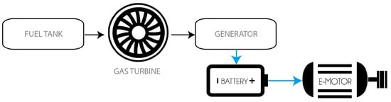
Figure 6.
A diagram of the configuration of MGT-ER.
2.1.6. Thermoacoustic Engine Extended Range (TAE-ER)
Most vehicles waste nearly a third of their fuel’s energy through the exhaust. Therefore, an efficient waste heat recovery process would undoubtedly improve fuel efficiency and reduce greenhouse gas emissions. Multiple waste heat recovery proposals exist. One of these is the thermoacoustic converter (TAC). The engine exhaust (hot side) and the coolant (cold side) produce a temperature differential that the TAC uses to produce electricity. Essentially, the TAC converts exhaust waste heat into electricity in two steps:
-
The exhaust heat is converted to acoustic energy (mechanical);
Three main stages illustrate how a TAE functions. The first is fuel burning in the combustion compartment, containing the combustion chamber blower and the combustion chamber. The second is the hot exhaust gases heading into the hot heat exchanger, transferring heat to the working fluids through a heat pipe. The third is the stack, which is the TAE’s thermal module area and is surrounded by a hot and cold reservoir on each side, exchanging heat. The cold reservoir exchanges heat through the cold HEX with the ambient air [59][60][59,60]. Figure 7 shows a diagram with the main components in a TAE-ER.
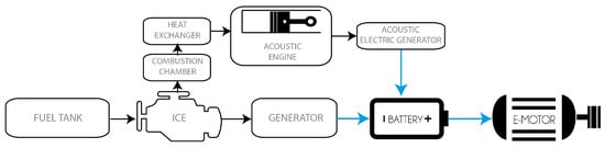
Figure 7.
A diagram of the configuration of TAE-ER.
2.1.7. Flywheel Energy Storage Extended Range (FES-ER)
A flywheel energy storage (FES) system has fast charge/discharge, is infinitely clean, and is highly efficient. The system consists of three energy storage components: a flywheel, a battery, and an ultra-capacitor. A flywheel is a rotating disk used as a mechanical energy storage device [61]. Two classes of materials are commonly used to fabricate the flyWheel, steel and composite materials. The difference is their rotational stress limitations. A composite-based flywheel can support higher speeds and rotational stress thresholds than a steel-based one. Therefore, composite materials can be used at high speeds (up to 100.00 rpm), whereas lower speeds (up to 10.000 rpm) apply to steel-based flywheels, which are heavier than the composite ones. The main limitation for the use of the composite material is its cost [62]. As a kind of short-term energy storage system, the FES system cannot be the primary power source of the vehicle. Therefore, a FES system with high power density is often used as an APU for a vehicle. The FES works while the vehicle brakes; it absorbs the RB energy. When the vehicle needs to accelerate, the FES system and the battery provide energy to the vehicle [31], as shown in Figure 8.
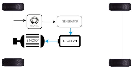
Figure 8.
A diagram of the configuration of FES-ER.
2.1.8. Solar Energy Storage Extended Range (SES-ER)
Solar photovoltaic cells (PVCs) generate electricity by absorbing sunlight and converting it to electric current. Vehicle companies favor solar energy storage (SES) systems for their cleanliness, safety, and economic performance. Studying efficient and stable SES systems has become critical for many automobile enterprises [63]. A car using a PVC improves autonomy by about 10% when used in a city [64]. Ezzat et al. [65] proposed a novel comprehensive energy storage system for EREV. The energy storage system proposed consists of PVCs, an FC, and batteries. The results showed that the addition of solar cells to the energy storage system of EREV could improve energy efficiency, perfectly complementing a range extender. Figure 9 shows the configuration of an FES-ER.
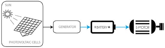
Figure 9.
A diagram of the configuration of SES-ER.
2.1.9. Rotatory Engine Extended Range (RE-ER)
Rotary engines (REs) are small in size, and their high power output makes multiple electrification technology solutions possible via a shared packaging layout. The rotary-powered range extender takes advantage of their compatibility with gaseous fuels: it works by burning liquefied petroleum gas to provide a source of electricity. A rotary engine has only two moving parts: the rotor and the shaft are inherently balanced with no oscillating components and produce minimal vibrations [66]. Each crankshaft revolution produces one rotor revolution, a complete engine cycle in each of the four chambers, and four power strokes [67]. Figure 10 shows the configuration of RE-ER.

Figure 10.
A diagram of the configuration of RE-ER.
Hydrogen combustion in a RE was carried out by Zambolov et al. [68], which complements the research about REs.
2.1.10. Wind Turbine Extended Range (WT-ER)
When a vehicle moves, it experiences wind resistance in two different forms—frictional drag and form drag. Frictional drag arises due to the viscosity of air, and form drag arises due to air pressure variation in the front and rear sides of the vehicle [69]. Suppose this wind energy is used to extract some power, not to create any component of force or thrust opposite the direction of the vehicle’s propulsion. In that case, the energy can produce electricity to charge up the EV battery itself. [66][70][71][66,70,71] presented a conceptual design of harnessing wind’s power to generate extra energy. Those designs can provide energy which could be stored or directly used to power electronic devices and vehicle instrumentation in a car or truck in movement. The use of wind energy in an EV can have different configurations, depending highly on the vehicle. One must not increase the drag coefficient to an extent that risks recovering the energy inefficiently. Figure 11 shows the configuration of WT-ER.
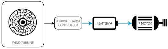
Figure 11.
A diagram of the configuration of wind energy extended range.