Acid Mine Drainage (AMD) is a toxic wastewater stream formed when oxygenated water comes into contact with exposed mine rock surfaces containing sulphide minerals. The formation of AMD is most prominent in abandoned mines where water accumulates in mine shafts and pits allowing exposure to sulphide minerals. The resulting AMD is typically characterised by a low pH with high concentrations of heavy metals and dissolved sulphate. When left untreated, AMD streams can cause severe environmental degradation, including the contamination of natural water bodies, destroying aquatic life and toxifying natural habitats. AMD remediation methods can be divided into two main categories, active treatment and passive treatment methods. Active treatment methods are characterised by process inputs such as energy, chemicals, labour and automated control, whereas passive remediation technologies require minimal process inputs and are mostly self-sustaining. Passive treatment methods are typically at source constructions comprising of a combination of naturally occurring geochemical, physical and biological processes.
- Acid Mine Drainage (AMD)
- geochemical classification
- AMD remediation technologies
1. Chemical Treatment
2
3) to neutralise the pH, resulting in the precipitation of heavy metals as metal oxides/hydroxides [1][2]. Chemical neutralisation may also incorporate aeration to oxidise reduced metals such as Fe
2+
3+, leading to increased precipitation [3]. An increased pH and the availability of calcium from calcium containing neutralising reagents enables some removal of high SO
4
4
2O) [1][4]. The major benefits of chemical treatment methods include the process scalability and versatility that enables the handling of any acidity loading and heavy metal concentrations, while being easy to operate and maintain [3][5][6].
1.1. Conventional Neutralisation
Conventional neutralisation processes consist of reaction tanks with stirrers for alkaline chemical dosing and reaction with the AMD [3]. The reaction tank is typically followed by a sedimentation process where the suspended solids are allowed to settle forming a hazardous Low-Density Sludge (LDS) of between 2–5% solids [7][8]. The supernatant quality contains low concentrations of heavy metals and neutralised pH [4]. However, conventional neutralisation is not effective at removing SO
4 [9]. The management of the LDS, the limited effectiveness of AMD remediation resulting in additional processing requirements and the continuous dosing of chemicals are key challenges associated with conventional neutralisation methods [5][10][11]. Conventional neutralisation and other neutralisation methods present opportunities for selective metal precipitation for metal recovery based on the solubility differences among metal compounds [12][13][14].
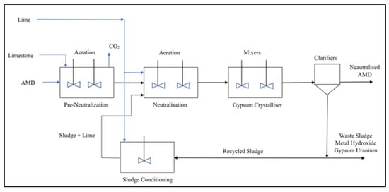
1.2. High Density Sludge
High Density Sludge (HDS) treatment is an improved neutralisation treatment method widely implemented globally for the primary treatment of AMD [10][2][4]. The HDS treatment process recycles and thickens the sludge with flocculation processes to form a hazardous high-density sludge of between 25–30% solids [3][2][15]. The sludge recycling promotes greater solids precipitation by providing a surface for heterogeneous nucleation to catalyse precipitation [16][17]. The HDS process utilises lime more efficiently and the sludge generated is especially high in gypsum [9][18]. The increased sludge density lowers the operational costs for sludge management, lowers the total footprint of the treatment works and produces an improved remediation quality over conventional neutralisation treatment [15][19]. It has been estimated that each megalitre of AMD produces 20 tons of toxic HDS [17][20]. The management of the toxic sludge generated by HDS processes remains a key challenge [17].
Figure 1
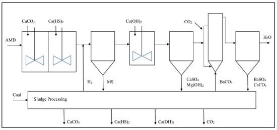
1.3. Chemical Desalination
HDS processes are still limited to low treated water quality, which has prompted further advancements in chemical treatment technologies through the development and deployment of chemical desalination processes such as the CSIR Alkaline–Barium–Calcium (ABC) process and the Magnesium–Barium–Hydroxide (MBO) process [22][23][21]. In the chemical desalination process, the pH is increased sequentially using alkaline reagents and calcium sulphide compounds leading to neutralisation and metal precipitation as metal sulphides and metal hydroxides. Lime or Mg(OH)
2
3
2
4
4 [22][24][25]. A variation is the use of calcium sulphide (CaS) with lime to increase the pH to above 10 and the precipitation of metals as hydroxides and sulphides [23][21][26]. A high degree of SO
4
4 in water, typically below 5 mg/L [27][28]. The pH is then dropped to below 8 through CO
2 dosing before effluent discharge. The advantages of chemical desalination include the high treated water quality, the use of readily available and affordable chemicals and the potential for chemical recover from the sludge for reuse to lower the chemical costs [23][21][24]. The challenges associated with chemical desalination include the use of toxic soluble compounds of Ba and the sludge generation that requires additional processing at an added cost [10].
Figure 2
1.4. Evaluation of Chemical Treatment Methods
4, Zn, Mg and Mn at the 80% distribution limit and their operational costs from the existing literature. Chemical desalination is capable of fully remediating AMD at the 80% distribution limit with the scalability to accommodate most AMD flowrates and becomes more economical at higher flows as a function of economies of scale [22][24][26]. Conventional neutralisation and the HDS process can effectively reduce acidity and Fe, Al, Mn and Zn concentrations, but are limited in SO
4 and Mg reduction [4][7][18]. The estimated operating costs excludes the additional sludge handling costs, which are site specific.
Table 1
Table 1.
| Criteria | Conventional Neutralisation | High Density Sludge | Chemical Desalination |
|---|
| pH neutralisation of acidic AMD pH = 2.0, acidity = 2000 mg/L |
Effective Treated pH > 8 |
Effective Treated pH > 8 |
Effective Treated pH > 8 |
| Removal of Total Fe removal Fe = 2800 mg/L |
Effective Treated Fe < 1 mg/L |
Effective Treated Fe < 1 mg/L |
Effective Treated Fe < 1 mg/L |
| Removal of Al removal Al = 500 mg/L |
Effective Treated Al < 1 mg/L |
Effective Treated Al < 1 mg/L |
Effective Treated Al < 1 mg/L |
| Removal of SO4 removal SO4 = 8000 mg/L |
Limited Treated SO4 > 2500 mg/L |
Limited Treated SO4 > 1900 mg/L |
Effective Treated SO4 < 200 mg/L |
| Removal of Zn removal Zn = 210 mg/L |
Effective Treated Zn < 1 mg/L |
Effective Treated Zn < 1 mg/L |
Effective Treated Zn < 1 mg/L |
| Removal of Mn removal Mn = 120 mg/L |
Effective Treated Mn < 5 mg/L |
Effective Treated Mn < 5 mg/L |
Effective |
[62][63]. However, additional energy is required for heating the influent AMD and cooling the treated permeate to maintain the differential temperature across the membrane that induces the vapour pressure gradient [61][63]. The feed temperatures can range from as low as 30 °C to as high as 90 °C [61][62]. MD technologies have various operating principals, which include direct contact, air gap and vacuum, amongst others, all of which have varying degrees of effectiveness [64][65].
Figure 5 shows a simplified process flow diagram of the simplest MD operating principal, namely direct contact [65].
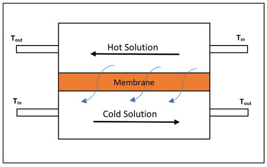
Figure 5. Process flow diagram of direct contact membrane distillation [65].
MD processes have lower equipment costs and lower pre-treatment requirements in comparison to RO processes; however, the technology has yet to be successfully scaled and commercialised for AMD desalination [61][64][66]. Theoretically, membrane distillation methods can achieve a 99.9% rejection of ions [67]. Another advantage of MD processes over desalination membranes is the minimal role the membrane has in the physical separation and the larger pore size that results in less membrane fouling [62]. However, high precipitant deposits have been observed on membrane surface, leading to the partial clogging of membrane pores when operating a submerged direct contact distillation membrane at a bench scale with a model AMD solution [63]. The biggest challenges associated with MD are the scalability of the process, the low permeate yield achieved in non-batch mode applications, the high energy requirements of the process per cubic meter of treated water and the high operational costs associated [62][67][68]. In addition, it has been estimated that MD can be more expensive to operate than RO at a commercial scale [67].
3.3. Evaluation of Membrane Treatment
4, Zn, Mg and Mn at the 80% distribution limit and their operational costs from the existing literature. Desalination was evaluated for the proven HiPRO process, which is highly efficient at AMD remediation. Due to the high energy requirements for both membrane technologies, the operational costs are dependent on the energy tariffs in the installed region [55]. Both methods can achieve a high remediation quality; however, MD is limited to low flow rates.
Table 3
Table 3.
| Criteria | Membrane Desalination | Reverse Osmosis-HiPRO Process |
|---|
| pH neutralisation of acidic AMD pH = 2.0, acidity = 2000 mg/L |
Ineffective at pH correction Pre-treatment required |
Effective Treated pH between 7–8 |
|
| Removal of Total Fe removal Fe = 2800 mg/L |
Effective Treated Fe < 0.3 mg/L |
Effective Treated Fe < 0.3 mg/L |
|
| Removal of Al removal Al = 500 mg/L |
Effective Treated Al < 0.3 mg/L |
Effective Treated Al < 0.3 mg/L |
|
| Removal of SO4 removal SO4 = 8000 mg/L |
Effective Treated SO4 < 250 mg/L |
Effective Treated SO4 < 250 mg/L |
|
| Removal of Zn removal Zn = 210 mg/L |
Effective Treated Zn < 5 mg/L |
Effective Treated Zn < 5 mg/L |
|
| Removal of Mn removal Mn = 120 mg/L |
Effective Treated Mn < 0.4 mg/L | Treated Mn < 5 mg/L | |
| Removal of Mg removal Mg = 300 mg/L |
Ineffective at changing Mg concentration | Ineffective at changing Mg concentration | Effective Treated Mg < 50 mg/L |
| Estimate operational costs | USD 1–0.5 | USD 1–0.5 | USD 0.25–0.75 |
| References | [10][23][29][30,32,55] | [10][17][18][29][30,45,46,55] | [22][10][23][24][5,30,32,50] |
2. Wetlands
Wetlands are large ecosystems with intense biogeochemical activity that play an important role in water treatment [30]. The remediation of AMD using wetlands is the most researched and implemented passive AMD treatment method globally due to the appealing self-sufficiency, pollution free treatment process and minimal maintenance requirements [1][31][32][33]. Wetlands make use of chemical, microbiological, phytoextraction and rizhofiltration processes for the remediation of AMD through the precipitation of metal hydroxides, Biological Sulphate Reduction (BSR), metal sulphide precipitation and direct uptake by living plants [31][33][34]. The vegetation growth, most commonly
Typha
Phragmites, on the submerged substrate of wetlands offers a continuous supply of carbon and energy for the microbiological community [35][36][37]. Wetlands are often preceded by limestone channels to neutralise the pH of AMD and aid in the metal precipitation in the wetland [38].
The application of wetland is limited to low acidity, low fluctuation of chemical composition and low flow rate AMD sources [39][40]. The key challenges toward the implementation of wetland solutions are the large land area requirements to treat high flows of AMD, the reduction in performance overtime due to the metallic sludge accumulation leading to refurbishment requirements and the high investment costs associated with the construction of wetland systems [40][41][42]. There are two types of wetlands used for the remediation of AMD, namely aerobic wetlands and anaerobic wetlands.
Figure 3
2.1. Aerobic Wetlands
Aerobic wetlands (AeWs) are the most basic passive treatment technique available and are suitable for treating net alkaline AMD with high concentrations of Fe [43]. AeWs oxidise Fe
2+
2+ to a lesser extent, while allowing a sufficient hydraulic retention time for the settling of the metal hydroxides [44]. AeWs can also remove metals such as arsenic through co-precipitation due to the adsorption onto positively charged Fe
3+
4) [1]. The oxidation of ferrous iron is net acid generating and, thus, AeWs are mainly suited for the remediation of net alkaline AMD or for final stage AMD treatment [45][46]. AeWs comprise of shallow basins holding water depths of between 10 to 30 cm and the surface flow of AMD to maintain the oxidising conditions [43]. Plants and other vegetations play an important role in AeWs’ performance by regulating and diversifying water flows for optimal surface area utilisation, preventing flow channelling that can lead to reduced hydraulic retention times and stabilising the ferric iron precipitants [1][43]. The limited remediation capability coupled with the remediation application limited to only net-alkaline AMD sources makes the use of AeWs as a stand-alone solution unsuitable for the vast majority of AMD sources [45].
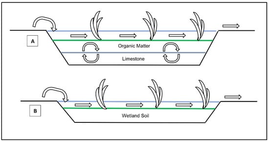
2.2. Anaerobic Wetlands
Anaerobic wetlands (AnWs) offer superior overall AMD remediation performance in comparison to aerobic wetlands. The remediation mechanisms involved in AnWs include biological sulphate reduction, the formation and precipitation of metal sulphides and the formation of carbonate alkalinity [44][47]. AnWs comprise of permeable layers of limestone, organic substrates, plants and other vegetation with water depths of greater than 30 cm to maintain anaerobic conditions [44]. The limestone layer generates alkalinity as a bicarbonate (HCO
3−
3, while the organic substrate layer provides a nutrient and energy supply for the consortium of microbial life [47][43]. One of the main microorganisms involved in AnWs’ remediation are Sulphate Reducing Prokaryotes (SRP), which reduce SO
4
2
3-
2S can react with dissolved metals causing precipitation as metal sulphides, while concurrently the dissolution of limestone results in an increased pH and further metal precipitation as metal hydroxides [48]. The precipitation of metals as metal sulphide is advantageous over metal hydroxide precipitation due to most metal sulphides being less soluble than metal hydroxides and having a smaller bulk volume, leading to sludge being more compact, which can extend the productive life of AnWs [48][49][50].
2.3. Evaluation of Wetlands
4
Table 2
Table 2.
| Criteria | Aerobic Wetlands | Anaerobic Wetlands |
|---|
| pH neutralisation of acidic AMD pH = 2.0, acidity = 2000 mg/L |
Ineffective Limited to treating net alkaline AMD |
Ineffective at treating pH of 2 Limited to treating pH > 4.5 |
| Removal of Total Fe removal Fe = 2800 mg/L |
Effective Fe < 1 mg/L |
Ineffective at changing concentration Pre-treatment required |
| Removal of Al removal Al = 500 mg/L |
Ineffective at changing concentration Pre-treatment required |
Ineffective at changing concentration Pre-treatment required |
| Removal of SO4 removal SO4 = 8000 mg/L |
Ineffective at changing concentration Pre-treatment required |
Ineffective at changing concentration Pre-treatment required |
| Removal of Zn removal Zn = 210 mg/L |
Ineffective at changing concentration Pre-treatment required |
Ineffective at changing concentration Pre-treatment required |
| Removal of Mn removal Mn = 120 mg/L |
Ineffective at changing concentration Pre-treatment required |
Ineffective at changing concentration Pre-treatment required |
| Removal of Mg removal Mg = 300 mg/L |
Ineffective at changing concentration Pre-treatment required |
Ineffective at changing concentration Pre-treatment required |
| Estimate operational costs | No direct cost | No direct cost |
| References | [45][3][10][11,23,30] | [45][47][40][11,31,64] |
3. Membrane Treatment
Membrane technologies include ultrafiltration, nanofiltration, reverse osmosis and membrane distillation amongst others and are generally operated as secondary treatment systems typically following HDS treatment [51][52]. A major benefit of secondary membrane treatment is the high treated water quality of up to potable water standards and the high water recovery rates, which can exceed 90% [53][54]. In addition, membrane treatment methods offer flexibility, scalability and compatibility with various primary remediation processes [14]. The high operational and maintenance costs of membrane technologies due to the high pressures required for membrane treatment and the inevitable scaling of membranes are the leading challenges associated with membrane treatment adoption for AMD remediation [10][23].
3.1. Membrane Desalination
Membrane desalination using Reverse Osmosis (RO) processes typically comprise of Ultrafiltration (UF) membranes and RO membranes [55][56]. In some AMD applications, Nanofiltration (NF) may also be used [55]. UF and NF membranes consist of fine pores, of approximately 0.01 and 0.001 microns, respectively, that can trap fine suspended solids and microorganisms in the solution, while allowing the filtered water to pass [57]. RO membranes are driven by positive hydrostatic pressure across a semi-permeable membrane where water molecules and some ions may pass through the membrane, while the remaining are retained in the membrane and discharged as a concentrated brine stream [51]. To increase the water recovery rate across an RO system, the concentrated stream from one RO stage can be fed into a second stage RO for further desalination and increased water recovery, as illustrated in
Figure 4 [51]. RO systems have high energy requirements due to the high operating pressures, while also requiring consistent antiscalant dosing to the influent to minimise the effects of membrane scaling, thereby promoting membrane lifespan and economic viability [58][59]. In addition, periodic Cleaning-In-Place (CIP) procedures with warm water and CIP chemicals are necessary to mitigate membrane fouling and the higher the influent Total Dissolved Solids (TDS) is, the more frequent the CIP requirements for membrane longevity are [60]. The described operational requirements contribute to the high operational costs associated with RO processes.
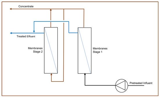
Figure 4.
RO processes with pre-treatment, typically HDS, have proven to be highly efficient at AMD remediation at a large commercial scale [54][56]. The eMalahleni Water Reclamation Plant in the Mpumalanga province of South Africa treats 30 megalitres per day of AMD to potable water quality with the TDS below 450 mg/L and over 98% recovery [54][56]. The process combines HDS pre-treatment with a multistage UF and RO process and is formally known as the Keyplan High Recovery Precipitating Reverse Osmosis (HiPRO
®) process [56]. However, due to the high operational and capital investment costs, this treatment option may only be viable for active mines where the costs can be absorbed by the mining operations and the treated potable water can be supplied to the local water supply grid to generate revenue, as is the case with the eMalahleni Water Reclamation Plant [54][56]. At a laboratory scale, AMD treatment using UF followed by NF and RO has been applied with promising outcomes [55]. However, the membrane longevity of this kind of approach at an industrial scale for the global 80% distribution would be a limitation.
Figure 4
3.2. Membrane Distillation
Membrane Distillation (MD) is a thermal driven physical separation process where a hot saline stream is separated into a cold purified stream and a concentrate stream using the vapour pressure difference induced by the differential temperature across the membrane, which results in the separation of dissolved ions from water [52][61]. The process consists of hydrophobic microporous membranes where water vapour molecules are passed through the membrane from the higher vapour pressure side to the low vapour pressure side [14]. MD is effective at the separation and rejection of ions, macromolecules and non-volatile organics present in AMD and can operate at lower pressures then RO systems that translate to energy cost and equipment cost reductions