Fluid Reaction Models: Comparison
Please note this is a comparison between Version 2 by Dean Liu and Version 1 by Alessio Alexiadis.

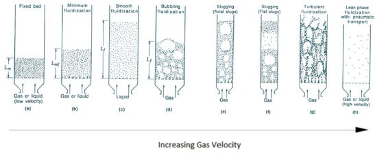
In the fluidized bed system, the performance of the reactor is affected by the hydrodynamic behaviors of the reactor in that fluid dynamics affects both heat and mass transfer.

  • solid–fluid reaction
  • reaction modelling
  • single particle reaction
  • fixed-bed reaction
  • fluidized-bed reaction

1. Introduction

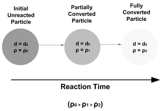
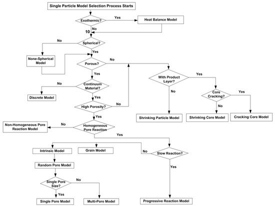
Different modelling methods have been developed to solve the reaction rate over the last few decades, from simplified models to complex CFD models. The simplest model is the shrinking particle model or shrinking core model for nonporous particles. More complex models include the random pore model, which accounts for the particle pore structure and the diffusion and reaction inside the pores.

While CFD simulation can provide detailed information on fluid dynamics and heat transfer in the solid/liquid reaction process, it is complex to build, requiring considerable computational resource and time. Therefore, for engineers who need a quick design of new product or process, or to perform a quick feasibility study or to evaluate or optimize the existing processes or operations within a limited time frame, CFD simulation could be too time-consuming to afford. In these cases, a quick modelling solution with appropriate correlations and empirical equations based on single particle reaction models becomes a desirable option.

2. Single Particle Reaction Models

Different models have been developed over the last few decades for a single particle reaction. Generally, according to the variations of particle size and density during the reaction, there are three basic types of model.
The first type is shrinking particle model or shrinking core model. These are the models when the particle is nonporous, and the reaction can only occur at the particle surface. Then the reaction zone moves into the solid, leaving behind the reaction product and inert solid if there is any. In the shrinking core model, the unreacted core shrinks in size during the reaction. However, the overall particle size can either remain unchanged or shrinking as the reaction progresses [29][1]. The former cases include coal/biomass combustion, where ash is left behind after reaction, keeping the particle diameter approximately unchanged. Therefore, the shrinking core model is also called the product layer model by some investigators [14][2]. For the reactions with no product layers formed outside the unreacted core, when products are either dissolved in the surrounding fluid or removed immediately from the outer surface of the solid, the shrinking core model is also called shrinking particle model, such as in the case of pure carbon combustion in oxygen, and the solid/liquid reaction producing gas products [30,31,32,33][3][4][5][6].
Some investigators considered the cracking of the nonporous particle during the reaction, and proposed the cracking core model [34[7][8],35], which assumes that the initial nonporous particle is transformed to a grainy material, which then reacts following the shrinking core model. This cracking core model has some success in simulating systems where intermediate products are formed during the reaction [34][7].
The second type is called progressive conversion model or volumetric reaction model or continuous reaction model. This is when the particle is highly porous, the reactivity is low, and the fluid reactant has a high possibility of diffusing far into the porous solid before reacting with the solid reactant, such as the slow poisoning of a catalyst pellet. Therefore, it can be assumed that the reaction occurs throughout the particle at all times. In this case, the concentration of fluid is generally uniform throughout the solid with the same value as that of the bulk fluid stream. The pores will become larger and the overall rate is independent of the solid size. The overall solid size does not change until the solid particle is highly converted [32,36,37,38][5][9][10][11]. The reaction process is shown in Figure 31.
Figure 31. Reaction process in progressive conversion model.
The third type is for the majority of porous particle reactions, where both the particle size and density reduce along the reaction process. In this case, the reaction can be seen as occurring homogeneously inside the solid. The homogeneous model has been developed to represent this scenario, including random pore model and grain model. The Ishid–Wen model [39][12] is developed for the cases where the reaction inside the pores is nonhomogeneous.
In summary, the reaction models developed for a single particle together with the model selection process, are shown in Figure 42.
Figure 42. Flowchart for singe particle reaction model selection process.

3. Reaction Models for Bed of Particles

Besides a single particle surrounded by fluid, as reviewed in the previous section, fixed bed and fluidized bed have also been used for the reactions involving large number of particles [72,73][13][14]. Fluid–solid fluidization occurs when particles are suspended in the flowing fluid and exhibit fluid-like properties. This can be achieved through either external forced draft or internally generated gas products which lift the particle.
Depending on the operational conditions, three hydrodynamic regimes can be found, i.e., bubbling fluidized bed, turbulent fluidized bed, and circulating fluidized bed [74][15]. A fluidized bed can be represented by a single bulk density and considered to be a heterogeneous mixture of fluid and solid.
All fluidized beds start as fixed beds with a minimum height when the fluid velocities are low. Further increasing the fluid velocity leads to a bubbling fluidization regime, with a high degree of mixing between the gas and solids phases in the case of gas-fluidized beds. In a bubbling fluidized bed with a relatively lower gas velocity, small gas bubbles are generated and grow up while rising in the bed. These bubbles become larger and less stable when the gas velocity is further increased, which are easy to break up. As a result, the fluidized bed begins to expand and transits from the bubbling to turbulent regimes, under which the fluctuations of the solid–gas flow inside the fluidized bed reaches its maximum, and the coalescence of the bubbles and the rates of the breakup reach the equilibrium [74,75][15][16]. The different fluidization regimes are shown in Figure 93.
Figure 93. Fluidization regimes of bed of particles ((a) Fixed bed; (b) Minimum fluidization; (c) Smooth fluidization; (d) Bubbling fluidization; (e) Slugging (Axial slugs); (f) Slugging (Flat slugs); (g) Turbulent fluidization; (h) Lean phase fluidization with pneumatic transport) (Kunii and Levenspiel [74][15]) (Copyright Elsevier).
Minimum fluidization velocity is required in order for the particles to become fluidized from a fixed bed. The fluidization velocity is the gas velocity calculated for the free cross-sectional area of the grate at bed pressure and temperature. The minimum fluidization velocity is the velocity where the fluid drag is equal to a particle’s weight and substracting its buoyancy.
The value of this minimum fluidization velocity depends on a number of parameters, including the size, shape, and polydispersity of the particles and the mode gas is injected into the system [76,77][17][18]. For example, the density, directly alters the net gravitational force on the particle, and therefore the minimum drag force, or velocity, required to lift a particle. The shape alters not only the relationship between the velocity and the drag force, but also the packing properties of the fixed bed, the associated void spaces and velocity of fluid through them.
When the fluid velocity is sufficiently high, the drag on an individual particle will exceed the gravitational force on the particle, and the particle will be entrained in the fluid and carried out of the bed. The point at which the drag on an individual particle is about to exceed the gravitational force exerted on it is the maximum fluidization velocity. Therefore, the entering fluid velocity must be above the minimum fluidization velocity and below the maximum fluidization velocity in order to maintain a bubbling or turbulent fluidized bed.
Compared to a fixed bed, a fluidized bed can induce intense mixing and contact between particles and fluid, leading to enhanced heat and mass transfer. Therefore, a thermal uniformity can be assumed to be similar to a well-mixed gas. Therefore, the fluidized bed can have high thermal capacity while maintaining a homogeneous temperature field. The diffusion also plays a less important role in fluidized bed because of higher heat and mass transfer rates between the gas and solid comparing to fixed bed.

References

  1. Iwaszenko, S.; Howaniec, N.; Smolinski, A. Determination of random core model parameters for underground coal gasification simulation. Energy 2019, 166, 972–978.
  2. Salmi, T.; Grenman, H.; Warna, J.; Murzin, D.Y. Revisiting Shrinking Particle and Product Layer Models for Fluid-Solid Reactions―From Ideal Surfaces to Real Surfaces. Chem. Eng. Process. Process. Intensif. 2011, 50, 1076–1084.
  3. Bhatia, S.K. The effect of pore structure on the kinetics of fluid-solid reactions. Ph.D. Thesis, University of Pennsylvania, Philadelphia, PA, USA, 1981.
  4. Gonzalez, J.A. Coupled fluid-solid thermal interaction modelling for efficient transient simulation of biphasic water-steam energy systems. Appl. Math. Model. 2020, 79, 566–593.
  5. Son, H.Y.; Roy, S. Fluid-solid reaction kinetics for solids of non-basic geometries: Application of the law of additive times in combination with the shape-factor methods. Metall. Mater. Trans. B 2020, 51, 601–610.
  6. Wen, C.Y. Noncatalytic heterogeneous solid–fluid reaction models. Ind. Eng. Chem. 1968, 60, 34–54.
  7. Martins, J.P.; Margarido, F. The cracking and shrinking model for solid–fluid reactions. Mater. Chem. Phys. 1996, 44, 156–169.
  8. Park, J.Y.; Levenspiel, O. The cracking core model for the reaction of solid particles. Chem. Eng. Sci. 1975, 30, 1207–1214.
  9. Gago, P.A.; Raeini, A.Q.; King, P. A spatially resolved fluid-solid interaction model for dense granular packs/soft-sand. Adv. Water Resour. 2020, 136, 103454.
  10. Ngo, S.I.; Lim, Y.I.; Lee, D.; Go, K.S.; Seo, M.W. Flow behaviours, reaction kinetics, and optimal design of fixed- and fluidized-beds for CO2 methanation. Fuel 2020, 275, 117886.
  11. Zhou, Z.; Yan, D.; Zhu, J.; Zheng, Y.; Li, H.; Zhu, Q. Simulation of the fluid-solid noncatalytic reaction based on the structure-based mass-transfer model: Shrinking core reaction. Ind. Eng. Chem. Res. 2020, 59, 17729–17739.
  12. Ishid, M.; Wen, C.Y. Comparison of kinetic and diffusional models for solid-gas reactions. AIChE J. 1968, 14, 311–317.
  13. Alexiadis, A.; Mazzarino, I. Design guidelines for fixed-bed photocatalytic reactors. Chem. Eng. Process. Process. Intensif. 2005, 44, 453–459.
  14. Alexiadis, A.; Baldi, G.; Mazzarino, I. Modelling of a photocatalytic reactor with a fixed bed of supported catalyst. Catal. Today 2001, 66, 467–474.
  15. Kunii, D.; Levenspiel, O. Fluidization Engineering; Butterworth-Heinemann: London, UK, 1991.
  16. Zhang, H.; Sun, Z.; Zhang, M.; Shao, Y.; Zhu, J. Comparison of the flow structure and regime transitions between a cylindrical fluidized bed and a square fluidized bed. Powder Technol. 2020, 376, 50–516.
  17. Alexiadis, A.; Gardin, P.; Domgin, J.F. Spot turbulence, breakup, and coalescence of bubbles released from a porous plug injector into a gas-stirred ladle. Metall. Mater. Trans. B 2004, 35, 949–956.
  18. Alexiadis, A.; Gardin, P.; Domgin, J.F. Probabilistic approach for break-up and coalescence in bubbly-flow and coupling with CFD codes. Appl. Math. Model. 2007, 31, 2051–2061.
More