The contemporary displacement measurement systems used in geotechnical laboratories during the determination of soil precise mechanical parameters, (e.g., the shear modules G: initial and in the range of small and very small strains) are not universal and their use depends on the type of soil (cohesive, non-cohesive), its condition (loose or dense, stiff or very soft), and its characteristic properties (e.g., organic soil, swelling soil).
- geotechnical laboratory
- soil parameters
- strain measurement systems
- X-ray tomography
- stereophotogrametry
- laser sensors
- encoder sensors
1. Introduction
The correct and precise determination of soil mechanical parameters in a controlled and homogeneous state of stress and deformation is an essential element of geotechnical and engineering design. It is worth paying attention to the use of “older” (from the 1970s) measuring systems in “newer” applications and to the latest, interesting solutions (in relation to strain measurement and results analysis) in geotechnical laboratories. The gradual development of measurement methods is primarily related to technological progress, which results in newer sensors and methods of data recording using induction phenomena (conductors, semi-conductors), resistivity, photoelectricity (lasers), piezoelectricity (piezoelectric crystals) and other combinations of different phenomena. The reference point in a geotechnical laboratory is usually a triaxial apparatus, considered by most researchers to be the mother of other devices that use and adapt its modern solutions. Traditional measurements of the axial deformation of the samples tested in the triaxial apparatus, carried out outside the cell, introduce significant errors in the calculation of the deformations [1]. Due to this, various types of internal displacement measurement systems began to develop, allowing to directly measure the deformation of the sample itself in its central zone (omitting the disturbance zone at the point of contact of the sample with the base and the top cap).
2. Small Displacement Zone—Local Measurement
There are two main groups of measurement systems: measurements covering the whole sample and local measurement, in which the sensors are inside the test cell. Local sensors may be attached to the sample (contact sensors, e.g., local deformation transducers (LDT), linear variable differential transformers (LVDT)), or not (non-contact sensors, e.g., proximity sensors (PT)). All soil measuring systems were originally dedicated to cylindrical samples in a triaxial apparatus. It is also worth noting that the accurate measurement of radial deformation is more difficult than that of the axial one, as the radial boundary of a specimen which is in the rubber membrane, is less rigid and produces less uniform measurements. Over time, these methods are modified and improved, especially those related to the measurement of radial deformations. For example, two new radial strain measurement devices were proposed by Chen et al. [2,3]. One of them is a system composed of two LVDTs mounted horizontally on a pair of yokes which are glued on the diametrically op-posite sides of the specimen [3]. The second is the compass-type mechanism (so-called floating) composed of two metal legs connected by a hinge and two FBG sensors. An added advantage is that the multiplexing capacity of FBG sensors enables the simultaneous measurement of strain or temperature at multipoints along one fiber line [2].
Another type of small deformation transducer (SDT) based on fiber Bragg grating sensors was proposed by Xu [4]. Xu showed that the SDT can be used for local deformation measurements (only the axial strains) of soil specimens in a modified triaxial apparatus as it has obvious merits such as light weight, high accuracy, resistance to cor-rosion and ease of handling [4].
The new magnetic encoders system with Fiber Bragg Grating (FBG) is another interesting proposition for researchers. This system is based on the Hall effect, with a wave re-ceiver outside the triaxial cell, which eliminates the need for using cables [5,6]. The mounting elements from the LVDT system were using in this solution.
2.1. Necessity of Strain Measuring—Modules G, E, K and Poisson’s Ratio
There are two main groups of measurement systems: measurements covering the whole sample and local measurement, in which the sensors are inside the test cell. Local sensors may be attached to the sample (contact sensors, e.g., local deformation transducers (LDT), linear variable differential transformers (LVDT)), or not (non-contact sensors, e.g., proximity sensors (PT)). All soil measuring systems were originally dedicated to cylindrical samples in a triaxial apparatus. It is also worth noting that the accurate measurement of radial deformation is more difficult than that of the axial one, as the radial boundary of a specimen which is in the rubber membrane, is less rigid and produces less uniform measurements. Over time, these methods are modified and improved, especially those related to the measurement of radial deformations. For example, two new radial strain measurement devices were proposed by Chen et al. [2][3]. One of them is a system composed of two LVDTs mounted horizontally on a pair of yokes which are glued on the diametrically op-posite sides of the specimen [3]. The second is the compass-type mechanism (so-called floating) composed of two metal legs connected by a hinge and two FBG sensors. An added advantage is that the multiplexing capacity of FBG sensors enables the simultaneous measurement of strain or temperature at multipoints along one fiber line [2].
Another type of small deformation transducer (SDT) based on fiber Bragg grating sensors was proposed by Xu [4]. Xu showed that the SDT can be used for local deformation measurements (only the axial strains) of soil specimens in a modified triaxial apparatus as it has obvious merits such as light weight, high accuracy, resistance to cor-rosion and ease of handling [4].
The new magnetic encoders system with Fiber Bragg Grating (FBG) is another interesting proposition for researchers. This system is based on the Hall effect, with a wave re-ceiver outside the triaxial cell, which eliminates the need for using cables [5][6]. The mounting elements from the LVDT system were using in this solution.
2.1. Necessity of Strain Measuring—Modules G, E, K and Poisson’s Ratio
The following ranges of deformations [7] have been experimentally distinguished: very small deformation (<10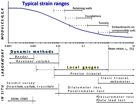
The bender elements (BE) can also be mounted in any geotechnical device capable of controlling stresses while measuring deformations, or vice versa, as mentioned by Ferreira [15]. Such equipment includes: odometer [16[16][17][18][19][20][21][22][23],17,18,19,20,21,22,23], direct shear apparatus [16,24][16][24], resonant-column [25[25][26][27][28],26,27,28], centrifuge [29[29][30],30], hollow cylinder [31,32[31][32][33],33], calibration chambers [34[34][35],35], true triaxial and cubical cell apparatus [36,37][36][37]. The other types of piezoelectric transducers are also used in geotechnical laboratories. These are a shear-plate (SP) [38,39,40,41,42,43][38][39][40][41][42][43] and a compression transducer (CT) [42].
3. Localisation and Development of Deformations in the Sample
Another group of experiments is related to the need for increasingly accurate registration of the localisation of deformations and the analysis of their development in a sample (material) under load, not only in geotechnics, but in the entire construction engineering. This issue is closely related to technological development and new opportunities. During several decades, new methods of recording displacements have appeared, based on optical (graphic) measurements, measurements using X-ray, thermal, electromagnetic, and other radiation. These methods are called “full-field methods” in experimental mechanics. Although they are included in the so-called internal systems, it should be remembered that all devices (video cameras, laser sensors, tomographic scanners) taking readings of deformation changes are located outside the test cell, not inside.
3.1. Overview of the Available Noninvasive Measurement Methods
The use of the PIV (DIC) method is widespread to identify the strain localization in loose materials (e.g., biaxial apparatus - element tests; [44,45][44][45] and in modeling the behavior of granular soil be-hind a retaining wall (model test; [46]). By combining the PIV method with digital photography and the discrete element method (DEM), it is possible to analyze granular media on the microstructure (single grain) level. In addition Hosseini et al. [47] and Srokosz et al. [48] showed the good agreement of the results obtained withstandard strain measurements with LVDT sensors and digital image correlation methods.
3.2. Stereophotogrammetry—2D optical Methods to Study Strain Localisation in Soil
Stereophotogrammetry, which is a type of photogrammetry, is a technology that al-lows to reproduce the shape, sizes, and mutual position of objects in three-dimensional space on the basis of a photo pair (stereograms). Most often, photogrammetry is associated with aerial photogrammetry (a wide coverage area), but it is also used for special purposes. In the geotechnical laboratory, stereophotography uses optical devices to measure the full-field displacement of a sample under loading [49,50][49][50]. It can be, for example, a system of two cameras placed on both sides of the sample, which at the same time record changes in two different planes. Stereophotogrammetry also helps to assess the influence of bending con-ditions and sample slenderness on the formation of various shear bands (bifurcation phenomenon, [51].
4. RTX-Based Methods
The first application of X-ray tomography in soil mechanics was in the early 1960s in Cambridge as a noninvasive technique for measuring strain field in soil which was documented by the Roscoe’s group [57] and later by Arthur [58]. From the early 1980s, this method was developed intensively by the researchers’ the group from Laboratory 3S-R in Grenoble (e.g., [44,59,60,61][44][59][60][61]) and later by Alshibli et al. [62].
The next stage of technological development in full-field analysis is the use of the synchrotron in soil research as a device combining three basic advantages: generation of much stronger X-rays, more precision and scanning speed. Higher energy and stronger photon beams result in higher image resolution, even to the micrometric scale. Such accuracy may not be as important in the case of coarsegrained soils, such as sand, for which the width of the shear band is about 10-20 grain diameters (about a few millimeters). However, it is important during the test deformations in finegrained soils, e.g., clays, in which grains are much smaller, and thus the shear bands are definitely narrower.
X-ray tomography and image recording occur at the same time as loading the sample, without stopping the press while scanning. In Europe, since 2003, the three test stands (called Microtomotriax) are provided on the ID15 test line (ESRF-EBS: European Synchrotron Radiation Facility—Extremely Brilliant Source), for triaxial tests on samples from rocks and cohesionless soils.
4.1. Analysis of the Results—Combined X-ray Tomography and 3D DIC (V-DIC)
The X-ray tomography technology opens up new possibilities for understanding soil mechanics (in three-dimensional space), due to its high resolution and thus the possibility of analyzing the kinematics of single soil grains and interactions between all grains in the entire sample volume, during the loading process [59,63,64][59][63][64]. This method is not perfect, because in some cases it is difficult to trace the shear plane which is only visible if they are high compaction or loosening (dilatancy or crack opening) in its zone. Such a limitation can be overcome by complementing X-ray computed tomography with 3D/continuum volume/discrete volume digital image correlation (DIC/CV-DIC/DV-DIC), which is a mathematical tool to define the best mapping of an image into another.
5. Laser Methods
Although each of the optical methods (video cameras, laser sensors, tomographic scanners) has been developed for many years (laser sensors are relatively the youngest; the first mention of them appeared in 2004 (e.g., [65,66][65][66]). The optical distortions of the sample recorded image are their most serious disadvantage. For this reason, e.g. Messerklinger et al. [66] and Srokosz et al. [48] introduced many modifications to the triaxial apparatus (e.g., changing the cell shape from cylindrical to cuboid, using contrasting colors of the grid with marks on the sample and illumination with an LED lamp). Generally, it was seen that radial strain measurement with the laser scanning the device turned out to be more precise in the range of small and very small strain.
6. Interesting Solutions
Among the modern measurement systems, there are many interesting solutions related to the modernization of research devices. For example, they are:
- .
- A miniaturized odometer with an optical microscope function developed by Bolton and his co-workers
- .
- An odometer and a direct shear apparatus equipped with bender elements by Lee et al.
- , Yun and Santamarina
- , Byun et al.
- .
- A Triaxial Apparatus “In Situ” - an unique device protected by Reiffsteck’s patent
- . In its concept, this device refers to the construction of a high-class, modernized triaxial apparatus and a self-boring pressuremeter. The device is equipped with Hall and LVDT sensors for measuring axial and radial deformations even in the small strain range. Any stress paths can be performed thanks to the construction of the apparatus. The samples may be cylindrical or rectangular shape (possibility of determining the parameters under anisotropy conditions). They are cut from the soil below the surface at any depth and covered directly with a rubber membrane. Thanks to this solution within the stage of sample preparation avoided are the operations causing the most disturbances: transport, storage, and installation in the apparatus. This is why the in situ triaxial testing can be highly recommended in case of noncohesive and weak cohesive soils. The triaxial tests “in situ” can be performed almost continuously, one after the other, on successive depth levels.
References
- Clayton, C.R.I.; Khatrush, S.A. A new device for measuring local axial strains on triaxial specimens. Geotechnique 1987, 37, 413–417, doi:10.1680/geot.1987.37.3.413.
- Jastrzębska, M. Investigations of the Behaviour of Cohesive Soils Subject to Cyclic Loads in the Area of Small Defor-mations; Silesian University of Technology: Gliwice, Poland, 2010. (in Polish).
- Scholey, G.K.; Frost, J.D.; Lo Presti, D.C.F.; Jamiolkowski, M. A review of instrumentation for measuring small strains during triaxial testing of soil specimens. Geotech. Test. J. 1995, 18, 137–156, doi:10.1520/GTJ10318J.
- Roscoe, K.H.; Arthur, J.R. F.; James, R.G. The determination of strains in soils by an X-ray method. Civ. Engng Publ. Wks. Rev. 1963, 58, 873–876, and 58, 1009–1012.
- Arthur, J.R.F. New techniques to measure new parameters. In Proceedings of the Roscoe Memorial Symposium: Stress-strain Behaviour of Soils, Cambridge, UK, 29–31 March 1971; Parry, R.H.G., Roscoe, K.H., Eds.; pp. 340–346.
- Bourdeau, P.L. Radiographic visualization in experimental soil mechanics. In Proceedings of the Conference on Digital Image Processing: Techniques and Applications in Civil Engineering, Kona, Hawaii, USA, 28 February–5 March 1993; Frost, J.D., Wright, J.R., Eds.; American Society of Civil Engineers: New York, NY, USA, 1993; pp. 125–134. Available online: http://worldcat.org/isbn/0872629791 (accessed on 22 August 2007).
- Hall, S.A.; Bornert, M.; Desrues, J.; Pannier, Y.; Lenoir, N.; Viggiani, G.; Bésuelle, P. Discrete and continuum analysis of localized deformation in sand using X-ray micro CT and Volumetric Digital Image Correlation. Géotechnique 2010, 60, 315–322, doi:10.1680/geot.2010.60.5.315.
- Tengattini, A.; Lenoir, N.; Andò, E.; Giroud, B.; Atkins, D.; Beaucour, J.; Viggiani, G. NeXT-Grenoble, the Neutron and X-ray tomograph in Grenoble. Nucl. Instrum. Methods Phys. Res. Sect. A Accel. Spectrometers Detect. Assoc. Equip. 2020, 968, 163939, doi:10.1016/j.nima.2020.163939.
- Butterfield, R.; Harkness, R.M.; Andrawes, K.Z. A stereo-photogrammetric technique for measuring displacement fields. Geotechnique 1970, 20, 308–314. doi:10.1680/geot.1970.20.3.308.
- Desrues, J. Tracking strain localization in geomaterials using computerized tomography. In Proceedings of the Interna-tional Workshop on Xray CT for Geomaterials, GEOX2003, Kumamoto, Japan, 6–7 November 2003; Otani, J., Obara, Y., Eds.; Balkema: Lisse, The Netherlands; 2004, pp. 15-41.
- Zhao, C.; Koseki, J. An image-based method for evaluating local deformations of saturated sand in undrained torsional shear tests. Soils Found. 2020, 60, 608–620, doi:10.1016/j.sandf.2020.02.012.
- Messerklinger, S.; Bleiker, E.; Zweidler, A.; Springman, S.M. Displacement measurement with laser scaninig in triaxial testing apparatuses. In Proceedings of the 16th European Young Geotechnical Engineers Conference, EYGEC, Vienna, Austria, 7–10 July 2004; Brandl, H., Ed.; Österr. Ingenieur- und Architekten-Verein: Vienna, Austria, 2004; pp. 251–260.
- Srokosz, P.; Bujko, M.; Bocheńska, M.; Ossowski, R. Optical Flow Method for Measuring Deformation of Soil Specimen Subjected to Torsional Shearing. Measurement 2021, 174, 109064, doi:10.1016/j.measurement.2021.109064.
- Tatsuoka, F. State-of-the-Art Paper: Some Recent Developments in Triaxial Testing Systems for Cohesionless Soils. In Ad-vanced Triaxial Testing of Soil and Rock; Donaghe, R.T., Chaney, R.C., Silver, M.L., Eds.; ASTM: Phiadelphia, PA, USA, 1988; pp. 7–67, doi:10.1520/STP29068S.
- Goto, S.; Tatsuoka, F.; Shibuya, S.; Kim, Y.S.; Sato, T. A simple gauge for local small strain measurements in the laborato-ry. Soils Found. 1991, 31, 169–180. doi:10.3208/sandf1972.31.169.
- Yimsiri, S.; Soga, K.; Chandler, S.G. Cantilever-type local deformation transducer for local axial strain measurement in triaxial test. Geotech. Test. J. 2005, 28, 445–451, doi:10.1520/GTJ11432.
- Enomoto, T.; Koseki, J.; Tatsuoka, F.; Sato, T. Rate-dependent behaviour of undisturbed gravelly soil. Soils Found. 2016, 56, 547–558, doi:10.1016/j.sandf.2016.04.018.
- Burland, J.B.; Symes, M. A simple axial displacement gauge for use in the triaxial apparatus. Geotechnique 1982, 32, 62–65, doi:10.1680/geot.1982.32.1.62.
- Jardine, R.J.; Symes, M.J.; Bourland, J.B. The measurement of soil stiffness in the triaxial apparatus. Géotechnique 1984, 34, 323–340, doi:10.1680/geot.1984.34.3.323.
- Ackerly, S.K.; Hellings, J.E.; Jardine, R.J. Discussion. A new device for measuring local axial strains on triaxial specimens. Geotechnique 1987, 3, 414–415. doi:10.1680/geot.1986.36.4.593.
- Holubec, I.; Finn, P.J. A lateral deformation transducer for triaxial testing: Research note. Can. Geotech. J. 1969, 6, 353–356. doi:10.1139/t69-033.
- Kolymbas, D.; Wu, W. Device for lateral strain measurement in triaxial tests with unsaturated specimens. Geotech. Test. J. 1989, 12, 227–229, doi:10.1016/0148-9062(90)94372-z.
- Lawrence, F.V. Ultrasonic Shear Wave Velocity in Sand and Clay; Research report R65-05, Soil Publication No. 175; Massa-chusetts Institute of Technology: Cambridge, MA, USA, January 1965.
- Brignoli, E.G.; Gotti, M.; Stokoe, K.H.I. Measurement of shear waves in laboratory specimens by means of piezoelectric transducers. Geotech. Test. J. 1996, 19, 384–397, doi:10.1520/GTJ10716J.
- Dyvik, R.; Madshus, C. Laboratory measurements of gmax using bender elements. in advances in the art of testing soils under cyclic conditions. In Proceedings of the ASCE Convention, Detroit, MI, USA, 24 October 1985; Khosla, V., Ed.; ASCE Geotechnical Engineering Division: New York, NY, USA, 1985; pp. 186–196.
- Suwal, L.; Kuwano, R. Disk shaped piezo-ceramic transducer for P and S wave measurement in a laboratory soil speci-men. Soils Found. 2013, 53, 510–524, doi:10.1016/j.sandf.2013.06.004.
- Heymann, G.; Clayton, C.R.I.; Reed, G.T. Triaxial ultra-small strain measurements using laser interferometry. Geotech. Test. J. 2005, 28, 544–552, doi:10.1520/GTJ10406.
- Xu, D.S.; Borana, L.; Yin, J.H. Measurement of small strain behavior of a local soil by fiber Bragg grating-based local dis-placement transducers. Acta Geotech. 2014, 9, 935–943, doi:10.1007/s11440-013-0267-y.
- Chen, W.B.; Feng, W.Q.; Yin, J.H.;Qin, J.Q New FBG-based device for measuring small and large radial strains in triaxial apparatus. Can. Geotech. J. Rev. Can. Geotech. 2020, 1–16, doi:10.1139/cgj-2020-0145.
- Brown, S.F.; Snaith, M.S. The measurement of recoverable and irrecoverable deformations in the repeated load triaxial test. Geotechnique 1974, 24, 255–259, doi:10.1680/geot.1974.24.2.255.
- Menzies, B.K. Design, manufacture and performance of a lateral strain device. Geotechnique 1976, 26, 542–544, doi:10.1680/geot.1976.26.1.215.
- Cuccovillo, T.; Coop, M.R. The measurement of local axial strains in triaxial tests using LVDTs. Géotechnique 1997, 47, 167–171, doi:10.1680/geot.1997.47.1.167.
- Chen, W.B.; Feng, W.Q.; Yin, J.H.; Borana, L. LVDTs-based radial strain measurement system for static and cyclic behav-ior of geomaterials. Measurement 2020, 155, 1–10, doi:10.1016/j.measurement.2020.107526.
- Witowski, M. Local displacement transducer with miniature position encoder. Geotech. Test. J. 2018, 41, 1147–1154, doi:10.1520/GTJ20170016.
- Witowski, M. Local measurements of axial and radial strains using magnetic encoders in triaxial apparatus. In E3S Web of Conferences, Proceedings of the 7th International Symposium on Deformation Characteristics of Geomaterials, IS-Glasgow 2019, Glasgow, Scotland, UK, 26–28 June 2019; Tarantino, A., Ibraim, E., Jardine, R., Eds.; EDP Sciences: Les Ulis, France, 2019; Volume 29, doi:10.1051/e3sconf/20199202002.
- Cole, D.M. A Technique for measuring radial deformation during repeated load triaxial testing. Can. Geotech. J. 1978, 15, 426–429, doi:10.1139/t78-039.
- Hird, C.; Yung, P. The use of proximity transducers for local strain measurements in triaxial tests. Geotech. Test. J. 1989, 12, 292–296, doi:10.1520/GTJ10987J.
- Brown, S.F.; Austin, G.; Overy, R.F. An instrumented triaxial cell for cyclic loading of clays. Geotech. Test. J. 1980, 3, 145–152, doi:10.1520/GTJ10911J.
- O'Kelly, B.C.; Naughton, P.J. Use of proximity transducers for local radial strain measurements in a hollow cylinder ap-paratus. In Proceedings of the 4th International Symposium on Deformation Characteristics of Geomaterials; IS Atlanta 2008, Atlanta, Georgia, USA, 22–24 September 2008; Burns, S.E., Mayne, P.W., Santamarina, J.C., Eds.; IOS Press: Am-stertdam, The Netherlands, 2008, Available online: http://hdl.handle.net/2262/67131 (accessed on 19 August 2013).
- Mishu, L.P. A Study of Stresses and Strains in Soil Specimens in the Triaxial Test. Ph.D. Thesis, Purdue University, West Lafayette, IN, USA, 1966.
- Jastrzębska, M.; Kowalska, M. Triaxial tests on weak cohesive soils—some practical remarks (part 2). Arch. Civ. Eng. En-viron. 2016, 9, 81–94, doi:10.21307/acee-2016-037.
- Ferreira, C. The Use of Seismic Wave Velocities in the Measurement of Stiffness of a Residual Soil. Ph.D. University of Porto, Porto, Portugal, 2008.
- Isah, B.W.; Mohamad, H.; Harahap, I.S.H. Measurement of small-strain stiffness of soil in a triaxial setup: Review of local instrumentation. Int. J. Adv. Appl. 2018, 5, 15–26, doi:10.21833/ijaas.2018.07.003.
- Xu, D.S.X. A new measurement approach for small deformations of soil specimens using fiber bragg grating sensors. Sen-sors 2017, 17, 1016; doi:10.3390/s17051016.
- Witowski, M. Wireless Measurement of Soil Sample Deformation in a Triaxial Cell; Report No. P.416928, protection No. PAT.227464, Publisher: Patent Office of the Republic of Poland; 2018.
- Hanzawa, H.; Itoh, Y., Suzuki, K. Shear characteristics of a quick sand in the Arabian Gulf. Soils Found. 1979, 19, 1–15, doi:10.3208/sandf1972.19.4_1.
- Georgiannou, V.N.; Rampello, S.; Silvestri, F. Static and dynamic measurements of undrained stiffness on natural over consolidated clays. In Proceedings of the 10th European Conference on Soil Mechanics and Foundation Engineering, Florence, Italy, 26–30 May 1991; Balkema: Rotterdam, The Netherlands, 1991; Volume 1, pp. 91–95.
- Jastrzębska, M.; Kalinowska-Pasieka, M. Selected Research Methods in Modern Geotechnical Laboratory—From the Subsoil to the Soil Parameters; Silesian University of Technology: Gliwice, Poland, 2015; Volume 313. (In Polish)
- Atkinson, J.H.; Sällfors, G. Experimental determination of stress-strain-time characteristics in laboratory and in situ tests. In Proceedings of the 10th European Conference on Soil Mechanics and Foundation Engineering, Florence, Italy, 26–30 May 1991; Balkema: Rotterdam, The Netherlands, 1991; Volume 3, pp. 915–956.
- Mair, R.J. Developments in geotechnical engineering research: Applications to tunnels and deep excavations. Proc. Inst. Civ. Eng. Civ. Eng. 1993, 97, 27–41, doi:10.1680/icien.1993.22378.
- Tani, K. General report: Measurement of shear deformation of geomaterials—Field tests. In Proceedings of the 1st Interna-tional Conference on Pre-Failure Deformation Characteristics of Geomaterials, Sapporo, Japan, 12–14 September 1994; Shibuya, S., Mitachi, T., Miura, S., Eds.; Balkema: Rotterdam, The Netherlandes, 1994; Volume 2, pp. 1115–1132.
- Reiffsteck, P. Nouvelles Technologies D’essai en Mécanique des Sols. État de l’art. Paramètres de calcul géotechnique; Magnan, J.P., Ed.; Presses de l’ENPC/LCPC: Paris, France, 2002.
- Jastrzębska, M.; Łupieżowiec, M. The influence of the choice of strain modulus value on foundation settlement. Studia Geotech. Mech. 2011, 33, 31–39.
- Burland, J.B.; Georgiannou, V.N. Small strain stiffness under generalized stress changes. In Proceedings of the 10th Euro-pean Conference on Soil Mechanics and Foundation Engineering, Florence, Italy, 26–30 May 1991; Balkema: Rotterdam, The Netherlands, 1991; Volume 1, pp. 41–44.
- Burland, J.B. Small is beautiful—The stiffness of soils at small strains. 9th Bjerrum Memorial Lecture. Can. Geotech. Test. J. 1989, 26, 499–516, doi:10.1139/t89-064.
- Georgiannou, V.N. The Behaviour of Clayey Sands under Monotonic and Cyclic Loading. Ph.D. Thesis, University of London, London, UK, 1988.
- Jamiolkowski, M.; Lancellotta, R.; Lo Presti, D.C.F.; Pallara, O. Stiffness of toyoura sand at small and intermediate strain. In Proceedings of the13th International Conference on Soil Mechanics and Foundation Engineering, ICSMFE 1994, New Delhi, India, 5–10 January 1994; Publications Committee of XIII ICSMFE, Ed.; Balkema: Rotterdam, The Netherlands, Volume 1, pp. 169–172.
- Jardine, R.J. Some observations on the kinematic nature of soil stiffness. Soils Found. 1992, 32, 111–124, doi:10.3208/sandf1972.32.2_111.
- Jardine, R.J.; Fourie, A.; Maswoswe, J.; Burland, J.B. Field and laboratory measurements of soil stiffness. In Proceedings of the 11th International Conference on Soil Mechanics and Foundation Engineering, ICSMFE 1985, San Francisco, CA, USA, 12–16 August 1985; CRC Press: Boca Raton, FL, USA, Volume 1, pp. 511–514.
- Jardine, R.J.; Potts, D.M.; Fourie, A.B.; Bourland, J.B. Studies of the influence of non-linear stress-strain characteristics in soil—structure interaction. Géotechnique 1986, 36, 377–396, doi:10.1680/geot.1986.36.3.377.
- Jardine, R.J.; Potts, D.M.; St. John, H.D.; Hight, D.W. Some practical applications of a non-linear ground model. In Pro-ceedings of the 10th European Conference on Soil Mechanics and Foundation Engineering, Florence, Italy, 2–30 May 1991; Belkema: Rotterdam, The Netherlands, Volume 1, pp. 223–228.
- Jastrzębska, M. Calibration and Verification of One-Surface Elasto-Plastic Soil Model of Strongly Non-Linear Anisotropic Strengthening. Ph.D. Thesis, Silesian University of Technology: Gliwice, Poland, 2002. (In Polish)
- Lipiński, M.J.; Wolski, W.; Fioravante, V.; Jamiolkowski, M.B. Preliminary evaluation of hazard due to liquefaction for żelazny most tailings pond. In Soil Mechanics and Foundation Engineering, Proceedings of the 4th International Conference on Soil Mechanics and Foundation Engineering, ICSMFE 1997, Hamburg, 6–12 September 1997; Publications Committee of XIV ICSMFE, Ed.; Balkema: Rotterdam, The Netherlands, Volume 3; 1843–1846.
- Kuwano, J.; Katagiri, M. Recent state of laboratory stress-strain tests on geomaterials in Japan. In Advanced Laboratory Stress-Strain Testing of Geomaterials; Tatsuoka, F., Shibuya, S., Kuwano, R., Eds.; A.A. Balkema Publishers: Tokyo, Japan, 2001; pp. 47–52.
- Dyvik, R.; Olsen, T.S. Gmax measured in oedometer and DSS tests using bender elements. In Proceedings of the 12th In-ternational Conference on Soil Mechanics and Foundation Engineering, ICSMFE 1989, Rio dr Janeiro, Brazil, 13–18 Au-gust 1989; Publications Committee of XII ICSMFE, Ed.; Taylor & Francis: Milton Park, UK, Volume 1; 39–42.
- Fam, M.; Santamarina, C. Study of geoprocesses with complementary mechanical and electromagnetic wave measure-ments in an oedometer. Geotech. Test. J. 1995, 18, 307–314, doi:10.1520/GTJ10999J.
- Zeng, X.; Ni, B. Stress-induced anisotropic Gmax of sands and its measurement. J. Geotech. Geoenviron. Eng. 1999, 125, 741–49, doi:10.1061/(ASCE)1090-0241(1999)125:9(741).
- Zeng, X.; Grolewski, B. Measurement of Gmax and estimation of K0 of saturated clay using bender elements in an oe-dometer. Geotech. Test. J. 2005, 28, 264–274, doi:10.1520/GTJ11318.
- Yun, T.S.; Santamarina. J.C. Decementation, Softening, and Collapse: Changes in small-strain shear stiffness in K0 load-ing. J. Geotech. Geoenviron. Eng. 2005, 131, 350–358. 10.1061/(ASCE)1090-0241(2005)131:3(350).
- Wang, Y.H.; Ooi, G.L.; Gao, Y. New sensing technology and new applications in geotechnical engineering. In Proceedings of the 18th International Conference on Soil Mechanics and Geotechnical Engineering, ICSMGE 2013, Paris, France, 2–6 September 2013; Delage, P., Desrues, J., Frank, R., Eds.; Presses des Ponts: Paris, France, 2013; Volume 3, pp. 1909–1912. Available online: http://hdl.handle.net/1783.1/65825 (accessed on: 30 June 2014).