
Two-dimensional (2D) materials are generally defined as crystalline substances with a few atoms thickness.Two-dimensional transition metal dichalcogenide (2D-TMDs) semiconducting (SC) materials have exhibited unique optical and electrical properties. The layered configuration of the 2D-TMDs materials is at the origin of their strong interaction with light and the relatively high mobility of their charge carriers, which in turn prompted their use in many optoelectronic applications, such as ultra-thin field-effect transistors, photo-detectors, light emitting diode, and solar-cells. Generally, 2D-TMDs form a family of graphite-like layered thin semiconducting structures with the chemical formula of MX2, where M refers to a transition metal atom (Mo, W, etc.) and X is a chalcogen atom (Se, S, etc.). The layered nature of this class of 2D materials induces a strong anisotropy in their electrical, chemical, mechanical, and thermal properties. In particular, molybdenum disulfide (MoS2) is the most studied layered 2D-TMD.
- layered materials
- 2D-MoS2
- pulsed laser deposition
- chemical vapor deposition
- photovoltaic
- gas sensors
- plasmonics
1. MoS2
From a crystalline point of view, layered MoS
exists in three polymorphic crystalline structures: 1T (tetragonal) [1], 2H (hexagonal) [2], and 3R (rhombohedral) [3] (
). The crystallographic parameters associated to these crystalline forms are summarized in
. In the case of mono- to few-layer structures, 2H-MoS
is the most thermodynamically stable phase and thus the most commonly encountered. When the MoS
is in the monolayer form, it takes an octahedral or a trigonal prismatic coordination phase.
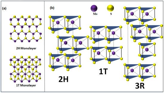
(
) Top view of 2H/1T MoS
monolayer. (
) Polymorphic structures of MoS
(2H is the hexagonal crystal form, 1T is the tetragonal crystal form, and 3R is the rhombohedral crystal form).
Crystal parameters and the nature of polymorphic structures of 2D-MoS
.
Furthermore, MoS
layered materials were observed to exhibit various shapes and morphologies, such as planar [4][5][6] and vertically aligned nanosheets (NSs) [7], nanoflowers [8], nanotubes [9], nanowires [10], and nanoplatelets [11][12]. This variety of forms could be controlled by choosing suitable synthesis routes with optimized operating parameters [8][9][10][11][13][14][15][16][17]. Thus, it is possible to adjust the 2D-MoS
properties to develop high performance devices i energy storage [17], electronics [16], photonics [15], sensing [18], and field emission [19] applications. Recently, up to few-layer MoS
nanosheets have been shown to be highly efficient for electronic, optoelectronic, and solar energy harvesting devices [20][21][22] because of their tunable direct bandgap [23], strong light-absorption, and prominent photoluminescence with energies lying in the visible range (1.8–1.9 eV) [24].
Although Mo and S are strongly covalently bonded within an individual layer, adjacent sheets are linked together only by the very weak van der Waals interaction. This weak bonding provides a facile processing route such as mechanical or chemical exfoliation to form few- to monolayer MoS
films. Unlike graphene, 2D-MoS
is much less prone to surface contaminations, which offers a superior chemical stability to 2D-MoS2, making it more attractive for the above-mentioned applications [25][26][27].
2. Fabrication Techniques of 2D-MoS2
Tremendous efforts have been devoted to the synthesis of 2D-MoS
with controllable large-area growth and uniform atomic layers using both top-down and bottom-up approaches. The most commonly used processing routes are detailed in the following sub-sections along with their advantages and limitations.
2.1. Mechanical and Chemical Exfoliations
Mechanical exfoliation, also known as micromechanical cleavage, is a straightforward technique that takes advantage of the weak bonding between layers, for the production of high-quality mono- to few-layer MoS
[28][29][30]. It consists of exfoliating thin films of 2D-MoS
from a bulk MoS
crystal by using a low surface tension tape to break the weak interlayer bonds in a similar way as for grapheme [31]. Additional exfoliation of the extracted films may be needed to obtain few- to monolayer MoS
. Tapes could be attached to glass slides to achieve planar exfoliation and slow peeling. The obtained monolayers are usually transferred to an appropriate substrate for further analysis and testing.
The advantage of the mechanical exfoliation process lies in its simplicity that requires the sole use of a confocal microscope to localize the 2D-MoS
layers deposited on the substrate. Conveniently, this technique can produce high crystalline quality mono- to few layers with a lateral size up to few tens of micrometers, making them highly suitable for sensing applications. However, this approach suffers from a lack of a consistent control in producing the 2D monolayers as it is heavily user-dependent and does not permit the control of the size and/or thickness uniformity of the exfoliated 2D-MoS
layers [32]. Therefore, the mechanical exfoliation technique is not necessarily suitable for the production of 2D-MoS
layers intended for large-area and high-throughput applications.
Chemical exfoliation, on the other hand, appears as a promising approach to produce large quantities of mono- and few-layer MoS
nanosheets [30][33][34][35]. Eda et al. [24] reported a high yield of monolayer crystal synthesis using chemical exfoliation of bulk MoS
via Li intercalation. However, this approach may induce an alteration in the quality of the produced 2D-MoS
. For instance, the chemically exfoliated MoS
layers can lose their semiconducting properties because of the structural changes resulting from the Li intercalation process. However, this fabrication route stands by its ease of processing, low production costs, and suitability for catalysis and/or sensing applications [36].
2.2. Chemical Vapor Deposition
Chemical vapor deposition (CVD) is one of the most popular routes for large-scale, high-quality, and low-cost 2D-MoS
material production [19][37][38][39]. CVD is a bottom-up fabrication method at the equilibrium state, which enables the processing of layered 2D-MoS
with controlled morphology and good crystallinity while minimizing structural defects. The control of the CVD process is ensured by tuning the deposition parameters such as temperature, pressure, gas flow rate, precursor’s quantities, and substrate types. The 2D-MoS
synthesis via the CVD technique can be achieved by means of thermal vapor sulfurization (TVS), thermal vapor deposition (TVD), and thermal decomposition (TD). Deokar et al. [13] used TVS for high quality and vertically-aligned luminescent MoS
nanosheets. A similar process could be used to grow 2D-MoS
layers [6][40] by employing two sources, such as molybdenum thin film (below 20 nm) or molybdenum oxide (MoO
) powder deposited on a SiO
/Si substrate as a first precursor and the sulfur powder or gaseous sulfur source (H
S, etc.) as the second precursor [19][37][38][39][41][42]. A typical CVD sulfurization process (
a) is usually performed in a tubular furnace reactor, where a continuous argon flow (typical flow rate 100 sccm) is used as a carrier gas to stream the evaporated sulfur into the Mo source materials.
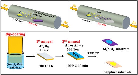
Schematic of the chemical vapor deposition techniques: (
) thermal vapor sulfurization process using a quartz tube; (
) thermal vapor deposition process using a quartz tube; and (
) thermal decomposition of (NH
)
MoS
(reproduced and adapted from Ref. [4]).
One of the critical aspects to be controlled in such a CVD tubular reactor is the temperature gradient between the S powder and the substrate. In fact, while the S powder is at 150–200 °C, the substrate’s temperature—with or without Mo thin film—should be maintained in the 700–900 °C range to obtain the 2D-MoS
phase. This technique offers sufficient latitude to fairly control the thickness and the homogeneity of the grown 2D-MoS
. The typical average lateral crystal size obtained by CVD is usually in the 10–30 nm range.
shows few examples of CVD-TVS grown MoS
nanostructures along with their associated processing conditions.
Examples of CVD-TVS grown MoS
nanostructures.
| Substrate | Precursors | Growth Conditions | Morphology | Ref |
|---|
| Si | MoO | 3 | and S powders dispersed on substrate | MoO | 3 | and S powders dispersed on substrate at 850 °C; S powder at 400 °C; Ar-0.725 L/min; time reaction = 30 min | MoS | 2 | nanosheets | [43] | [13] | |||||
| Si [001] | S powder and Mo film deposited on substrate | Mo deposited on Silicon at 850 °C, S at 400 °C; Ar-0.725 L/min; time reaction = 30 min | MoS | 2 | nanosheets | [44] | [14] | |||||||||
| Si/SiO | 2 | S powder and Mo film deposited on substrate | ||||||||||||||
| ≈22 nm | ||||||||||||||||
| [ | 86 | ] | [ | 56 | ] | |||||||||||
| Carbon nanotubes, Si-wafers and glass | bis(tbutylimino)bis(dimethylamino) Mo (VI) and H | 2 | S | 300 | 100–250 | 100 | ≈11 nm | [87] | [57] | |||||||
| Si, SiO | 2 | , Al | 2 | O | 3 | MoCl | 5 | and H | 2 | S | 3.75 | 430–480 | 1 | 1 layer | [88] | [58] |
| Si | MoCl | 5 | and H | 2 | S | – | 390–480 | 100 | ≈21.5 nm | [89] | [59] | |||||
| SiO | 2 | Mo hexacarbonyl and H | 2 | S | – | 175 | 100 | ≈5 nm | [90] | [60] |
The ALD appears as a potentially interesting technique for the production of high-quality MoS
ultrathin films at relatively low temperatures and with the ability to achieve excellent step coverage onto different substrates. However, the very low throughput of the ALD might hinder its scalability and competitiveness in comparison with other physical and/or chemical deposition methods.
2.4. Pulsed Laser Deposition
Pulsed laser deposition (PLD) has emerged as one of the most promising physical vapor deposition (PVD) techniques for the deposition of MoS
thin films. The PLD approach consists of shining a focused high-power laser beam onto the surface of a solid target to be ablated and deposited as a film on a substrate. PLD is a non-equilibrium process that leads to the absorption of very-short (15–20 ns) and highly-energetic laser pulses by the target and to the formation of a directive plasma plume. The laser-ablated species that form the plasma plume condense onto the substrate, leading to the growth of a thin film. The PLD is well known for its large process latitude, high-flexibility, and excellent process controllability. For instance, by controlling the number of laser ablation pulses and/or the background gas pressure, nanoparticles, and/or films with thicknesses varying from few nm to few microns can be synthesized.
shows a schematic representation of a PLD system.
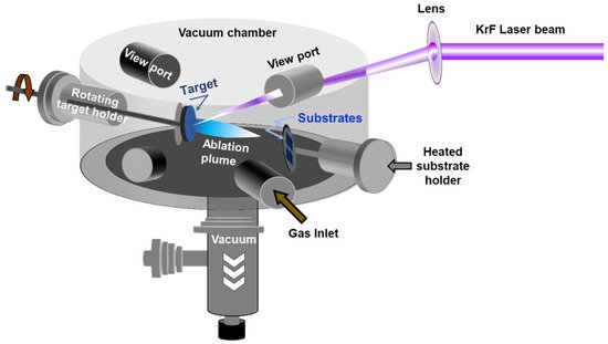
Schematic of the pulsed laser deposition chamber.
Among the advantages and the unique features of the PLD method, we can cite: (i) its ability to achieve a congruent transfer to the films when a multi-element target is used [61]; (ii) its highest instantaneous deposition rate along with the highly-energetic aspect of the ablated species (~10 times higher than in sputtering) enables the growth of metastable phases and/or crystalline phases even at room temperature; and (iii) its process latitude, which makes it easy to control almost independently each of the deposition parameters (laser intensity, number of laser ablation pulses, background gas pressure, and substrate temperature), and hence the properties of the deposited materials [62][63][64]. While the early studies on the PLD of MoS
date back to the 1990s [65][66][67][68][69][70], it is only recently that important advancements have been made in PLD synthesis of 2D-MoS
films onto various substrates opening thereby the way to their use for different optoelectronic applications. In 2014, PLD was successfully used to grow one to several layers of MoS
onto different metal, semiconducting, and sapphire substrates [71][72]. Siegel et al. [73] were the first to report, in 2015, the growth of MoS
films (from 1 to a few 10s of monolayers thick) on centimeter-sized areas. Other attempts were made to deposit ultrathin (≤3 nm) films of nearly-stoichiometric amorphous MoS
onto irregular surfaces such as silicon and tungsten tips and to study their field electron emission (FEE) properties [65]. The authors stated that the addition of the MoS
coating is beneficial to the FEE process since lower electric fields were required to extract an electron current density of 10 μA/cm
(namely, 2.8 V/μm for MoS
-coated Si and ~5.5 V/μm for MoS
-coated W tips). More recently, PLD has been used to fabricate high-quality MoS
films (monolayer to few layers) and integrated them into functional ultraviolet (UV) photodetectors [74]. The developed photodetectors were found to exhibit a very low dark current (~10 × 10
A), low operating voltage (2 V), and good response time (32 ms). Their performance surpassed that previously reported for 2D-MoS
synthesized by other routes [75][76][77][78][79]. Indeed, under UV irradiation, their detectivity, photoresponse (I
/I
ratio), and responsivity were found to be as high as 1.81 × 10
Jones, 1.37 × 10
, and 3 × 10
A/W, respectively.
summarizes most of the papers reported so far on the PLD of MoS
films. More specifically, it compares the main PLD growth conditions of 2D-MoS
films along with the obtained crystallographic phase and some of the reported optoelectronic properties.
Summary of the PLD conditions of MoS
films along with their thickness and some of their properties.
| Substrate | Target | P(Pa) | T(°C) | Laser Energy | Thickness | Properties | Ref |
|---|
| Stainless steel | MoS | 2 | 2.66 × 10 | −6 | RT/200/300/450 | 5 mJ | ≈400 nm | Granular structure stoichiometric, crystalline MoS | 2 | [110] | [80] | ||||
| Stainless steel | MoS | 2 | 10 | −6 | RT/300 | 100 mJ | ≈70 nm | Stoichiometric single crystal MoS | 2 | [111] | [81] | ||||
| c-Al | 2 | O | 3 | (0001) and Si/SiO | 2 | 2H-MoS | 2 | 9.33 × 10 | −4 | 600 | 500 mJ/cm | 2 | ≈1.4 nm | Stoichiometric 2H phase Flake size ≈ 10 µm |
|
| ] | |||||||||||||||
| fluorophlogopite mica | |||||||||||||||
| MoS | |||||||||||||||
| 2 | |||||||||||||||
| 10 | |||||||||||||||
| −5 | |||||||||||||||
| 700 | |||||||||||||||
| 4000 mJ/cm | |||||||||||||||
| 2 | |||||||||||||||
| ≈3.3 nm | |||||||||||||||
| 2H phase MoS | |||||||||||||||
| 2 | [ | 125 | ] | [ | 95 | ] | |||||||||
| Al | 2 | O | 3 | (0001) | MoS | 2 | 10 | −3 | 650 | 100 mJ | ≈400 nm | 2H phase MoS | 2 | [126] | [96] |
2.5. Other Processing Routes
In addition to the main fabrication methods presented above, other PVD techniques have been used to deposit 2D-MoS
films. Among these methods, magnetron sputtering has been used to deposit both MoS
and WS
films onto polydimethylsiloxane (PDMS) polymer substrates [7][97][98][99][100] with controllable defect densities. The PDMS substrate was chosen to fabricate flexible devices based on 2D-semiconducting materials. Interestingly, very smooth MoS
surfaces, with a roughness of less than 2 nm, were achieved by casting the polymer on a polished silicon wafer. It has also been shown that it is possible to induce subsequent crystallization of MoS
by exposing it to a pulsed 532 nm laser [97].
Finally, the use of any of the above-discussed techniques to fabricate 2D-MoS
films is mostly dictated by the availability of the equipment, expertise, and requirements of targeted application. In a general context, the physical-chemical and optoelectronic properties of the final MoS
films will be determined to select the appropriate synthesis route. Nevertheless, the level of complexity, throughput, and fabrication costs have to be considered to choose the appropriate synthesis technique particularly when a technology has to be adopted.
provides a general comparison of the preparation techniques of MoS
described in this review by listing their main advantages and limitations.
Comparison of the advantages and limitations of different preparation techniques of MoS
.
| Techniques | Advantages | Limitations |
|---|
| Mechanical exfoliation |
|
| |||||||||
| Chemical exfoliation |
|
| |||||||||
| Chemical vapor deposition |
| Mo deposited on Silicon at 850 °C, S at 400 °C; Ar-0.725 L/min; time reaction = 30 min | MoS | 2 | nanosheets | [49] | [19] | ||||
| Diamond substrate | S powder and Mo deposited on substrate | Mo deposited on Silicon with S powder at 800 °C; N | 2 | ; ambient pressure; time reaction = 30 min | Horizontally and vertically MoS | 2 | [73] | [43] | |||
| Si/SiO | 2 | S powder and MoO | 3 | deposited on substrate | MoO | 3 | film deposited on Silicon at 750–850 °C, 600 mg of S powder at 100 °C; Ar-0.01 L/min; time reaction = 10 min | Mono-to few-layers of MoS | 2 | [74] | [44] |
shows the typical morphologies obtained for MoS
, which seem to depend on the carrier gas and the type of the substrate used. The reaction time and the spatial position of the substrate strongly affect the number of resulting layers.
The TVD based MoS
growth (
b) involves the concomitant evaporation of both MoO
and S powders. This approach consists of a stepwise sulfurization of MoO
to form the MoS
phase. It has been shown that, by increasing the S vapor flux, the sulfurization proceeds through several phase changes before reaching the final product. First, MoO
is formed, then MoO
followed by MoOS
, and finally MoS
. This approach is very useful to obtain 2D MoS
layers with a lateral size of few tens of microns. The TVD growth conditions of MoS
under various conditions and with different characteristics are summarized in
.
Examples of TVD grown MoS
along with their relevant processing conditions (* D is the distance between the MoO
and
powders inside the tubular furnace).
| Substrate/Setup | MoO | 3 | (mg) | S (mg) | D * (cm) | Gas, Flow (sccm) | T (°C), Time (min) | Morphology | Ref |
|---|
| Si face-down | 15 | 80 | 18 | Ar 10 to 500 |
700, 30 | Flake size between 5.1–47.9 µm |
. It also leads to a p-type MoS
semiconductor by increasing the electrons deficiency. In contrast, the presence of sulfur vacancies in MoS