Uranyl carbonate phases play a very important role in all processes related to the nuclear fuel cycle. under the influence of groundwaters enriched with CO2, which can be derived from the dissolution of host carbonate rocks or from the atmosphere [1][2][3][4][5][1,2,3,4,5]. In dissolved form, uranyl carbonates can play an important role in U release to the environment. And of course, it should not be forgotten that uranyl-carbonate mineralization has been described among the alteration products of the “lavas” that were formed during the accident at the fourth reactor of the Chernobyl nuclear power plant in 1986 [6][7][6,7].
There are 40 uranyl carbonate mineral species approved by the International Mineralogical Association as of 1 November 2020, thus making this group one of the most representative among secondary uranium minerals, coming third only after phosphates and sulfates [8][9][8,9]. Despite a fairly large number of known compounds, the structural diversity is not as great as one might expect. It is also of interest that about a quarter of approved minerals still have their crystal structures undetermined. The amount of synthetic structurally characterized uranyl carbonates is inferior to natural phases but can give an idea of the crystallization conditions present in the environment.
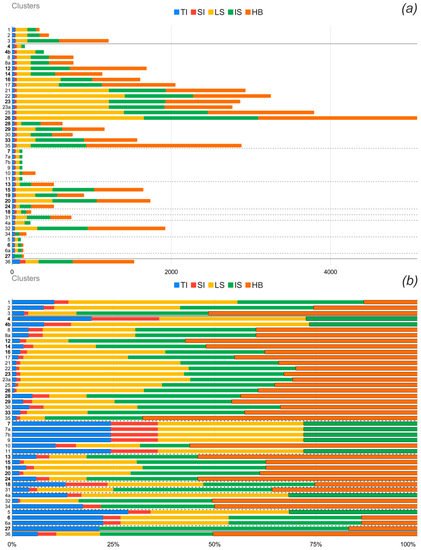
Current work is devoted to reviewing the topological diversity and growth conditions of natural uranyl carbonates and their synthetic analogs. Information-based complexity measures have been performed to determine contributions of various substructural building blocks and particular topological types into the complexity of the whole structure, which is related to the stability of a crystalline compound.
First of all, it should be noted that the number of synthetic phases for which the structures were determined is significantly inferior to the structurally characterized natural uranyl carbonates in the ratio of 19:32. Whereas for other groups of U(VI)-bearing compounds this proportion is usually opposite
[8][10][11][8,127,133]. The first structurally characterized synthetic uranyl carbonate, to our knowledge, was one of the simplest phases
4a, sodium-bearing Na
4(UO
2)(CO
3)
3 [12][17]. It is of interest that the first crystal structure of the natural uranyl carbonate, rutherfordine (
41), was reported the year before
[13][85]. The papers of K. Mereiter from the TU Wien (Austria) should be certainly noted in the first row among the works devoted to the synthesis and structural studies of synthetic uranyl carbonates. Then, the studies carried out by the A.M. Fedoseev and I.A. Charushnikova from the Frumkin Institute of Physical chemistry and Electrochemistry RAS (Russian Federation) and by V.N. Serezhkin from the Samara State University (Russian Federation) should be mentioned. A substantial portion of the synthetic uranyl carbonate compounds was synthesized and studied by P. C. Burns and his colleagues from the University of Notre Dame (USA), who significantly contribute to the studies of uranyl carbonate minerals as well.
All synthetic experiments can be roughly divided into two groups. Moreover, the majority of inorganic uranyl carbonates were synthesized by evaporation at room temperature and only a few of them were obtained from hydrothermal conditions. Uranyl nitrate hexahydrate was usually used as the source of U. But in some experiments, more specific reagents were used: UO
2 powder (for
1 and
2), UO
2(CO
3) (for
7a), Ag
4[UO
2(CO
3)
3] (for
8a), α-UO
2MoO
4(H
2O)
2 (for
10), and Na
4UO
2(CO
3)
3 (for
21). Potassium, sodium, cesium, or thallium carbonates were used as the source of CO
3 ions within the synthetic experiments. Compounds
36 and
10 can be considered as exceptions due to the usage of guanidine carbonate and carbamide in the respective syntheses. Several protocols of synthetic experiments deserve special attention. Thus, compound
1 [14][11] was formed as the result of the dissolution of UO
2 powder in the solution of K
2CO
3 and H
2O
2 at room temperature. Later it was filtered through a 0.45 µm polyamide syringe filter, and an additional 1.5 mL of 35 wt% H
2O
2 was added. Afterward it was transferred to a borosilicate scintillation vial and layered with methanol. The compound
2 [15][12] was obtained similarly, except for the scintillation vial step. The crystals of
4a [16] were obtained by hydrothermal synthesis at 135 °C in a sealed silica glass tube at about 20 MPa. The compound
7a [17][27] was synthesized by evaporation at room temperature, but before being left to evaporate, the dissolution of the precipitate was achieved via heating the solution over a steam bath. The crystals of
7b [18][28] were obtained from the solution that was stirred for five days. The compound
11 [19][33] was synthesized by slow addition of uranyl nitrate solution to the solution of Tl
2(CO
3)
2 at the temperature of c.a. 57 °C. The solvent was removed in a vacuum desiccator for two months from the resulting yellow-green solution, and crystals were then taken from the precipitate. To obtain the crystals of
36 [20][74], the initial solution was stirred vigorously for several days, afterwards, it was centrifuged and the supernatant was removed via pipet. The crystals were obtained from the precipitate, which was slowly cooled to 5 °C under a CO
2 atmosphere.
Nine of uranyl carbonate minerals have synthetic analog, which was also obtained mostly by evaporation at room temperature, except for the crystals of
7 [21][26], which were formed during the two months of evaporation at vacuum-desiccator. The compound
4a [22][15] was synthesized by hydrothermal reaction at 220 °C. The crystals of
41 [23][20] were obtained by purging the solution of UO
3 with 70 kPa CO
2 at the glove box for 24 h.
Very special attention can be paid to compound
4a [22][15], which may be the same sodium uranyl carbonate that was found among alteration products of the “lavas” resulting from the nuclear accident of the Chernobyl nuclear power plant
[6][7][6,7].
3. Topological Analysis
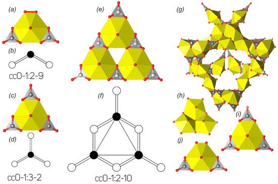
The majority of uranyl carbonate crystal structures are based on finite clusters, which are represented by only two topological types (). The topological variety of layered uranyl carbonate complexes is significantly larger; however, the amount of compounds, which structures are based on the 2D units, is much lower. There are only ten uranyl carbonate compounds known with a layered structure, and all of them are natural phases.
The crystal structures of two synthetic K-bearing uranyl carbonates
1 [14][11] and
2 [15][12] differing only in the hydration state and one uranyl carbonate, templated by guanidinium molecules
3 [24][13], are based on the finite clusters of the
cc0-1:2-9 topological type (
Figure 1a,b). In terms of polyhedral representation, these clusters can be described as a hexagonal bipyramid that shares two of its equatorial edges with CO
3 groups spaced by one non-shared equatorial edge. There is a peroxide molecule arranged in the equatorial plane spaced from a carbonate group by another non-shared edge. Such topological type was also described in the structures of two uranyl nitrate compounds, pure inorganic
[25][134] and organically templated
[26][135], in which the peroxide group was replaced by two H
2O molecules. It should be noted that this topological type has an isomer, if two equatorial CO
3 groups are
trans-arranged, being spaced by two non-shared edges, in contrast to the
cis-arrangement in the structures of
1–
3. The
trans-isomer is one of the most common types of uranyl nitrate finite clusters
[27][136], while it has not been observed in the structures of uranyl carbonates at all.
Figure 12. Finite clusters in the crystal structures of natural and synthetic uranyl carbonates and their graphical representations (see and text for details). Legend: see ; peroxide molecule is indicated by red bond (
a); see
Section 3.3 for details.
Uranyl tricarbonate cluster (UTC), which is shown in Figure 1c, is the most common structural unit among the natural and synthetic uranyl carbonate phases. There are 39 compounds known (), whose structures are based on these finite clusters, and is in sum 2.5 times more than the amount of all other structurally characterized uranyl carbonates (15). The topology of UTC belongs to the cc0-1:3-2 type (Figure 1d). This topology can be obtained from the previous cis-cc0-1:2-9 type by the replacement of the peroxide molecule by the third CO3 group, resulting in the formation of a triangular cluster with the uranyl hexagonal bipyramid arranged in its core and ideal -6m2 point group symmetry.
Table 1. Crystallographic characteristics of natural and synthetic uranyl carbonates.
| No. |
Chemical Formula |
Mineral Name |
Sp.Gr. |
a, Å/
α, ° |
b, Å/
β, ° |
c, Å/
γ, ° |
Ref. |
| Finite Clusters |
| cc0-1:2-9 |
| 1 |
K4[(UO2(CO3)2(O2)](H2O) |
|
P21/n |
6.9670(14)/90 |
9.2158(18)/91.511(3) |
18.052(4)/90 |
[14] |
| 2 |
K4[(UO2(CO3)2(O2)](H2O)2.5 |
|
P21/n |
6.9077(14)/90 |
9.2332(18)/91.310(4) |
21.809(4)/90 |
[15] |
| 3 |
(CN3H6)4[UO2(CO3)2(O2)]·H2O |
|
Pca21 |
15.883(1)/90 |
8.788(2)/90 |
16.155(1)/90 |
[24] |
| cc0-1:3-2 |
| 4 |
Na4(UO2)(CO3)3 |
Čejkaite |
Cc |
9.2919(8)/90 |
16.0991(11)/91.404(5) |
6.4436(3)/90 |
[28] |
| 4a |
Na4(UO2)(CO3)3 |
|
P-3c |
9.3417/90 |
9.3417/90 |
12.824/120 |
[22][16][12] |
| 4b |
Na4(UO2)(CO3)3 |
Cejkaite
old model |
P-1 |
9.291(2)/90.73(2) |
9.292(2)/90.82(2) |
12.895(2)/120.00(1) |
[29] |
| 5 |
K3Na(UO2)(CO3)3 |
|
P-62c |
9.29(2)/90 |
9.29(2)/90 |
8.26(2)/120 |
[30] |
| 6 |
K3Na(UO2)(CO3)3(H2O) |
Grimselite |
P-62c |
9.2507(1)/90 |
9.2507(1)/90 |
8.1788(1)/120 |
[23][31][32][33] |
| 6a |
Rb6Na2((UO2)(CO3)3)2(H2O) |
Rb analogue of
Grimselite |
P-62c |
9.4316(7)/90 |
9.4316(7)/90 |
8.3595(8)/120 |
[34] |
| 7 |
K4(UO2)(CO3)3 |
Agricolaite |
C2/c |
10.2380(2)/90 |
9.1930(2)/95.108(2) |
12.2110(3)/90 |
[35] |
| 7a |
K4UO2(CO3)3 |
|
C2/c |
10.247(3)/90 |
9.202(2)/95.11(2) |
12.226(3)/90 |
[21] |
| 7b |
K4(UO2)(CO3)3 |
|
C2/c |
10.240(7)/90 |
9.198(4)/95.12(4) |
12.222(12)/90 |
[17] |
| 58 |
Rb4(UO2)(CO3)3 |
|
C2/c |
10.778(5)/90 |
9.381(2)/94.42(3) |
12.509(3)/90 |
[18] |
| 8 |
Cs4UO2(CO3)3(H2O)6 |
|
P21/n |
11.1764(4)/90 |
9.5703(4)/ 96.451(2) |
18.5756(7)/90 |
[36] |
| 8a |
Cs4(UO2(CO3)3)(H2O)6 |
|
P21/n |
18.723(3)/90 |
9.647(2)/96.84(1) |
11.297(2)/90 |
[37] |
| 9 |
Cs4(UO2(CO3)3) |
|
C2/c |
11.5131(9)/90 |
9.6037(8)/93.767(2) |
12.9177(10)/90 |
[38] |
| 10 |
(NH4)4(UO2(CO3)3) |
|
C2/c |
10.679(4)/90 |
9.373(2)/96.43(2) |
12.850(3)/90 |
[39] |
| 11 |
Tl4((UO2)(CO3)3) |
|
C2/c |
10.684(2)/90 |
9.309(2)/94.95(2) |
12.726(3)/90 |
[19] |
| 12 |
Mg2(UO2)(CO3)3(H2O)18 |
Bayleyite |
P21/a |
26.560(3)/90 |
15.256(2)/92.90(1) |
6.505(1)/90 |
[40][41] |
| 13 |
CaMg(UO2)(CO3)3(H2O)12 |
Swartzite |
P21/m |
11.080(2)/90 |
14.634(2)/99.43(1) |
6.439(1)/90 |
[40][42][43] |
| 14 |
Ca2(UO2)(CO3)3(H2O)11 |
Liebigite |
Bba2 |
16.699(3)/90 |
17.557(3)/90 |
13.697(3)/90 |
[40][44][45][46] |
| 15 |
Ca9(UO2)4(CO3)13·28H2O |
Markeyite |
Pmmn |
17.9688(13) |
18.4705(6) |
10.1136(4) |
[47] |
| 16 |
Ca8(UO2)4(CO3)12·21H2O |
Pseudomarkeyite |
P21/m |
17.531(3) |
18.555(3) |
9.130(3)/103.95(3) |
[48] |
| 17 |
Sr2UO2(CO3)3)(H2O)8 |
|
P21/c |
11.379(2)/90 |
11.446(2)/93.40 (1) |
25.653(4)/90 |
[49] |
| 18 |
Na6Mg(UO2)2(CO3)6·6H2O |
Leószilárdite |
C2/m |
11.6093(21)/90 |
6.7843(13)/91.378(3) |
15.1058(28)/90 |
[50] |
| 19 |
Na2Ca(UO2)(CO3)3(H2O)5.3 |
Andersonite |
R-3m |
17.8448(4)/90 |
17.8448(4)/90 |
23.6688(6)/120 |
[23][40][44][51][52][53][54][55][56][57][58][59][60][61] |
| 20 |
Na2Ca8(UO2)4(CO3)13·27H2O |
Natromarkeyite |
Pmmn |
17.8820(13) |
18.3030(4) |
10.2249(3) |
[48] |
| 21 |
Ca3Na1.5(H3O)0.5(UO2(C O3)3)2(H2O)8 |
|
Pnnm |
18.150(3)/90 |
16.866(6)/90 |
18.436(3)/90 |
[62] |
| 22 |
K2Ca(UO2)(CO3)3·6H2O |
Braunerite |
P21/c |
17.6725(12)/90 |
11.6065(5)/101.780(8) |
29.673(3)/90 |
[63] |
| 23 |
K2Ca3[(UO2)(CO3)3]2·8(H2O) |
Linekite |
Pnnm |
17.0069(5)/90 |
18.0273(5)/90 |
18.3374(5)/90 |
[64] |
| 23a |
K2Ca3((UO2(CO3)3)2(H2O)6 |
|
Pnnm |
17.015(2)/90 |
18.048(2)/90 |
18.394(2)/90 |
[65] |
| 24 |
SrMg(UO2)(CO3)3(H2O)12 |
Swartzite-(Sr) |
P21/m |
11.216(2)/90 |
14.739(2)/99.48(1) |
6.484(1)/90 |
[40][42] |
| 25 |
Na0.79Sr1.40 Mg0.17
(UO2(C O3)3)(H2O)4.66 |
|
Pa-3 |
20.290(3)/90 |
20.290(3)/90 |
20.290(3)/90 |
[66] |
| 26 |
MgCa5Cu2(UO2)4(CO3)12
(H2O)33 |
Paddlewheelite |
Pc |
22.052(4)/90 |
17.118(3)/90.474 (2) |
19.354(3)/90 |
[67] |
| 27 |
Na8[(UO2)(CO3)3](SO4)2·3H2O |
Ježekite |
P-62m |
9.0664(11)/90 |
9.0664(11)/90 |
6.9110(6)/120 |
[68] |
| 28 |
NaCa3(UO2)(CO3)3 (SO4)F(H2O)10 |
Schröckingerite |
P-1 |
9.634(1)/91.41(1) |
9.635(1)/92.33(1) |
14.391(2)/120.26(1) |
[40][69][70][71][72] |
| 29 |
MgCa4F2[UO2(CO3)3]2
(H2O)17.29 |
Albrechtschraufite |
P-1 |
13.569(2)/115.82(1) |
13.419(2)/107.61(1) |
11.622(2)/92.84(1) |
[73][74] |
| 30 |
Ca5(UO2(CO3)3)2(NO3)2
(H2O)10 |
|
P21/n |
6.5729(9)/90 |
16.517(2)/90.494(3) |
15.195(2)/90 |
[75] |
| 31 |
Ca6(UO2(CO3)3)2Cl4(H2O)19 |
|
P4/mbm |
16.744(2)/90 |
16.744(2)/90 |
8.136(1)/90 |
[75] |
| 32 |
Ca12(UO2(CO3)3)4Cl8(H2O)47 |
|
Fd-3 |
27.489(3)/90 |
27.489(3)/90 |
27.489(3)/90 |
[75] |
| 33 |
Nd2Ca[(UO2)(CO3)3](CO3)2
(H2O)10.5 |
Shabaite-(Nd) |
P-1 |
8.3835(5)/90.058(3) |
9.2766(12)/89.945(4) |
31.7519(3)/90.331(4) |
[76][77] |
| 34 |
[C(NH2)3]4[UO2(CO3)3] |
|
R3 |
12.3278(1)/90 |
12.3278(1)/90 |
11.4457(2)/120 |
[78] |
| 35 |
(C4H12N)4[UO2(CO3)3]·8H2O |
|
P21/n |
10.5377(18)/90 |
12.358(2)/99.343(4) |
28.533(5)/90 |
[79] |
| cc0-1:2-10 |
| 36 |
[C(NH2)3]6[(UO2)3(CO3)6]
(H2O)6.5 |
|
P-1 |
6.941(2)/95.63(2) |
14.488(2)/98.47(2) |
22.374 (2)/101.88(2) |
[20] |
| Nanoclusters |
| 37 |
Mg8Ca8(UO2)24(CO3)30O4
(OH)12(H2O)138 |
Ewingite |
I41/acd |
35.142(2)/90 |
35.142(2)/90 |
47.974(3)/90 |
[80] |
| Layers |
| 544234 (β-U3O8) |
| 38 |
CaU(UO2)2(CO3)O4(OH)
(H2O)7 |
Wyartite |
P212121 |
11.2706(8)/90 |
7.1055(5)/90 |
20.807(1)/90 |
[81][82][83] |
| 38a |
Ca(U(UO2)2(CO3)0.7O4(OH)1.6) (H2O)1.63 |
Wyartite
dehydrated |
Pmcn |
11.2610(6)/90 |
7.0870(4)/90 |
16.8359(10)/90 |
[84] |
| 61524232 (phosphuranylite) |
| 39 |
Ca(UO2)3(CO3)2O2(H2O)6 |
Fontanite |
P21/n |
6.968(3)/90 |
17.276(7)/90.064(6) |
15.377(6)/90 |
[85][86] |
| 61524236 (roubaultite) |
| 40 |
Cu2(UO2)3(CO3)2O2(OH)2
(H2O)4 |
Roubaultite |
P-1 |
7.767(3)/92.16(4) |
6.924(3)/90.89(4) |
7.850(3)/93.48(4) |
[87][88] |
| 6132-I (rutherfordine) |
| 41 |
(UO2)(CO3) |
Rutherfordine |
Imm2 |
4.840(1)/90 |
9.273(2)/90 |
4.298(1)/90 |
[23][89][13][90][91] |
| 42 |
Ca(H2O)3[(UO2)3(CO3)3.6O0.2] |
Sharpite |
Cmcm |
4.9032(4) |
15.6489(11) |
22.0414(18) |
[92] |
| 42a |
Ca(UO2)6(CO3)5(OH)4·6H2O |
Sharpite |
Orth |
21.99(2) |
15.63(2) |
4.487(4) |
[93][94] |
| 6132-II (widenmannite) |
| 43 |
Pb2[(UO2)(CO3)2] |
Widenmannite |
Pmmn |
4.9350(7)/90 |
9.550(4)/90 |
8.871(1)/90 |
[31][95][96][97] |
| Layers of Miscellaneous Topology |
| 44 |
Y2(UO2)4(CO3)3O4·14H2O |
Kamotoite-(Y) |
P21/n |
12.3525(5) |
12.9432 (5)/99.857(3) |
19.4409(7) |
[98][99] |
| 45 |
[(Y4.22Nd3.78)(H2O)25(UO2)16O8
(OH)8(CO3)16](H2O)14 |
Bijvoetite-(Y) |
B21 |
21.234(3)/90 |
12.958(2)/90.00(2) |
44.911(7)/90 |
[100][101] |
| 46 |
Ca(UO2)(CO3)2·5H2O |
Meyrowitzite |
P21/n |
12.376(3) |
16.0867(14)/107.679(13) |
20.1340(17) |
[102] |
| Minerals with Undefined Structures |
| 47 |
Cu2(Ce,Nd,La)2(UO2)(CO3)5
(OH)2·1.5H2O |
Astrocyanite-(Ce) |
Hex |
14.96(2)/90 |
14.96(2)/90 |
26.86(4)/120 |
[103] |
| 48 |
(UO2)(CO3)·H2O |
Blatonite |
Hex or Trig |
15.79(1)/90 |
15.79(1)/90 |
23.93(3)/120 |
[104] |
| 49 |
(UO2)(CO3)·nH2O |
Joliotite |
Orth |
8.16 |
10.35 |
6.32 |
[31] |
| 50 |
CaGd2(UO2)24(CO3)8Si4O28·
60H2O |
Lepersonnite-(Gd) |
Pnnm or Pnn2 |
16.23(3)/90 |
38.74(9)/90 |
11.73(3)/90 |
[100] |
| 51 |
Ca(UO2)(CO3)2·3H2O |
Metazellerite |
Pbn21 or Pbnm |
9.718(5) |
18.226(9) |
4.965(4) |
[105] |
| 52 |
(UO2)2(CO3)(OH)2·4H2O |
Oswaldpeetersite |
P21/c |
4.1425(6) |
14.098(3)/103.62(1) |
18.374(5) |
[106] |
| 53 |
Ca3Mg3(UO2)2(CO3)6(OH)4·
18H2O |
Rabbitite |
Mon |
32.6(1) |
23.8(1)/~90 |
9.45(5) |
[107] |
| 54 |
Ca(UO2)3(CO3)(OH)6·3H2O |
Urancalcarite |
Pbnm or Pbn21, |
15.42(3) |
16.08(4) |
6.970(6) |
[108] |
| 55 |
Ca2Cu(UO2)(CO3)4·6H2O |
Voglite |
P21 or P21/m |
25.97 |
24.50/104.0 |
10.70 |
[109][110] |
| 56 |
Ca(UO2)(CO3)2·5H2O |
Zellerite |
Pmn21 or Pmnm |
11.220(15) |
19.252(16) |
4.933(16) |
[105][111] |
| 57 |
CaZn11(UO2)(CO3)3(OH)20·
4H2O |
Znucalite |
Orth |
10.72(1) |
25.16(1) |
6.325(4) |
[112] |
| 57a |
CaZn12(UO2)(CO3)3(OH)22·
4H2O |
Znucalite |
Tricl |
12.692(4)/89.08(2) |
25.096(6)/91.79(2) |
11.685(3)/90.37(3) |
[113] |
Compound
36 [20][74], to our knowledge, is the only compound whose structure is based on the triuranyl hexacarbonate finite cluster (
Figure 1e). The cluster is built by three vertex-sharing in a cyclic manner uranyl hexagonal bipyramids. Each cavity at the exterior side of such a cycle is occupied by a CO
3 group to form a large triangle, each side of which is built by alternating two bipyramids and three carbonate groups. The topology of the uranyl carbonate cluster (
Figure 1f) in the structure of
36 belongs to the
cc0-1:2-10 type. The architecture of this cluster can be also described as trebling of the UTC cluster with keeping triangular motif and ideal -6
m2 point group symmetry.
Probably the most remarkable structure not only among the uranyl carbonate compounds but among all known minerals, was described in ewingite (
37)
[80][75]. Ewingite is a calcium-magnesium oxo-hydroxy-hydrate uranyl carbonate natural phase, whose structure is built by 24 uranyl pentagonal and hexagonal bipyramids interlinked with each other and CO
3 groups, to form nanoclusters 2.3 nm in diameter (
Fig
ure 1g). Three fundamental building units can be distinguished within the uranyl carbonate cluster in ewingite. These are 4 trimers of edge-sharing pentagonal bipyramids, 6
cis-isomer of the uranyl bicarbonate unit (
cc0-1:2-9), and 6 UTC complex (
Figure 1h–j). Moreover, linkage of all building units occurs only through the carbonate groups. Mg and Ca ions as well as H
2O molecules are arranged both inside and in between the U-bearing nanoclusters.
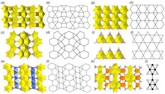
The crystal structures of wyartite (
38)
[81][82][83][84][76,77,78,79] and its dehydrated form are based on the similar layered complexes that belong to the so-called β-U
3O
8-sheet anion topology (a,b). Topology has the 5
44
23
4 ring symbol and consists of infinite chains of edge-sharing pentagons that are linked with the neighbor chains through the common vertices and separated by the chains of squares and triangles. The crystal structures of
38 and
38a are remarkable for being the only U(V)-bearing natural phases. Pentagons are occupied by the U
6+ ions, squares correspond to the irregular U
5+O
7 polyhedra, whereas triangles are vacant. Carbonate groups share edges with the U
5+-centered polyhedra and are arranged towards the interlayer space.
Figure 23. 2D complexes in the crystal structures of natural and synthetic uranyl carbonates and their anion topologies or graphical representation (see and text for details).
Legend: see ; Cu polyhedra = blue, Nd or Y polyhedra = orange; see Section 3.3 for details.
The crystal structure of fontanite (
39)
[85][86][80,81] is based on the layered uranyl carbonate complexes, which correspond to the, so-called, phosphuranylite anion topology
[114][137] (
Figure 2c,d) with the 6
15
24
23
2 ring symbol. The topology consists of two types of alternating infinite chains. The first type of chains is formed by edge-sharing dimers of pentagons that are interlinked by edge-sharing hexagons. The second type of chain is formed by alternating edge-sharing triangles and squares. All hexagons and pentagons are occupied by the uranyl ions, all triangles are occupied by carbonate groups, while all squares are vacant. It should be noted that phosphuranylite anion topology is very common among the U-bearing natural and synthetic phases and is represented by a wide variety of isomers, which differ in the occupancy of polygons. Thus, hexagons may be vacant, and triangles may be occupied by tetrahedral, trigonal pyramidal, or planar trigonal oxyanions (e.g.,
[8][10][8,127]).
Another anion topology that consists of hexagons, pentagons, squares and triangles with the 6
15
24
23
6 ring symbol (
Figure
2e,f) was described in the structure of roubaultite (
40)
[87][88][82,83]. Roubaultite anion topology contains the same infinite chains of edge-sharing pentagon dimers linked by edge-sharing hexagons that were observed in the phosphuranylite topology. But in the structure of
40, these chains are separated by infinite chains of edge-sharing squares decorated with trimers of edge-sharing triangles on the sides. All hexagons and pentagons are also occupied by the uranyl ions, as I was realized in the phosphuranylite topology. Squares are occupied by Cu-centered slightly distorted octahedra. The middle triangle from each trimer is occupied by the carbonate group, leaving the other two triangles vacant.
The simplest uranyl carbonate, at least according to the chemical composition, rutherfordine (UO
2)(CO
3)
[23][89][13][90][91][20,84,85,86,87], has a layered structure. The anion topology is also rather simple; it consists of parallel chains of edge-sharing hexagons separated by hourglass dimers of edge-sharing triangles (g,h). All hexagons are occupied by the uranyl ions, and one triangle from each dimer is occupied by the CO
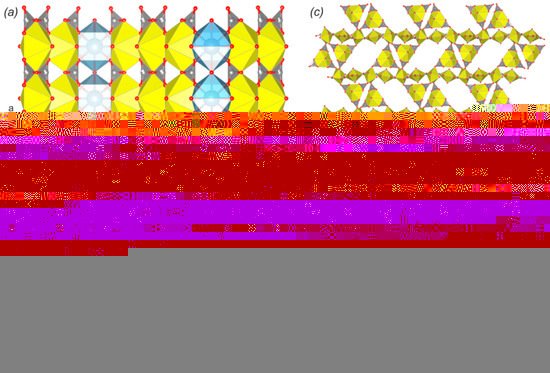
3 group, keeping the second triangle vacant. The crystal structure of sharpite (
42) is also based on the layered complexes that belong to the same rutherfordine anion topology. However, the polyhedral representation appeared to be much more complex. Thus, the layer can be described as being formed by the 1D modules of rutherfordine topology. Each module represents a triple band of edge-sharing uranyl hexagonal bipyramids, a part of the triangular spaces between which are occupied by carbonate groups. These modules are arranged in the structure at approximate right angles to each other and are linked by the Ca-centered polyhedra, which are arranged on the crests of sawtooth waves (
Figure 3a,b). Despite the curvature of such zigzag layers (in contrast to flat layered structure in rutherfordine) and the arrangement of Ca ions in the centers of square antiprisms, projection of such corrugated layers onto the (010) plane corresponds to the rutherfordine topology, with the equatorial arrangement of Ca polyhedra ligands having hexagon shape.
Figure 34. The crystal structures of sharpite (a,b) and meyrowitzite (c) with simplified topological representation (d). Legend: see ; Ca polyhedra = light blue.
The crystal structure of widenmannite (
43)
[31][95][96][97][21,91,92,93] is based on layered complexes, the topology of which consists of hexagons and triangles with the same 6
13
2 ring symbol as was found in the structure of rutherfordine. However, the arrangement of polygons in both structures is different. Widenmannite anion topology is built by the hexagons linked by vertex-sharing to other six hexagons, while all of its six edges are shared with triangles, thus forming trihexagonal tiling, which was used by Johannes Kepler in his book
[115][138] and is also known under the kagome pattern name. In the ideal structure of the widenmannite (
Figure 2i,j) each second row of hexagonal bipyramids should be vacant, but in the real structure the disorder with partial occupancy of the U sites takes place, which results in the occupation of all hexagons by the uranyl ions and half of the triangles oriented in the same direction are occupied by carbonate groups, keeping another half vacant.
The crystal structures of two
REE-bearing minerals kamotoite-(Y) (
44)
[98][99][94,95] and bijvoetite-(Y) (
45)
[100][101][96,97] are based on highly remarkable and very rare layered complexes that have not been observed in any other natural or synthetic compound. The topology of the 2D complex is based on infinite chains of alternating dimers of edge-sharing uranyl hexagonal and pentagonal bipyramids (
Figure 2k,l). Dimers of pentagonal bipyramids are arranged along the chain’s extension, while dimers of hexagonal bipyramids are arranged perpendicularly. Each hexagonal bipyramid shares two of its oblique equatorial edges, not taking part in the linkage between U polyhedra, with CO
3 groups. These chains are linked into the 2D structure via irregular Y
3+- or Nd
3+-centered coordination polyhedra through the 6th non-shared equatorial edge from one chain and two O atoms of two carbonate groups from the neighbor chain. It should be noted that the resulting U- and
REE-bearing layers are electroneutral, so the 3D structure formation is provided by the H-bonding system, which involves H
2O molecules from the coordination sphere of
REE atoms and from the interlayer space.
The final to date topological type, which has been described in the structures of natural and synthetic uranyl carbonates, is observed in the structure of calcium uranyl carbonate mineral meyrowitzite (
46)
[102][98]. The structure of the layered complex is composed of UTC clusters sharing apical vertices of CO
3 groups with uranyl pentagonal bipyramids (
Figure 3c). This structural type, unlike the rest of the topologies described herein, is the least dense in terms of the interconnection of U coordination polyhedra, and its topology will become clearer if graphical representation is used for illustration (
Figure 3d). Thus, if uranyl pentagonal bipyramid is represented by grey nods, U hexagonal bipyramids by white nods, and the line between nods appearing if pentagonal bipyramid shares an equatorial O atom with the CO
3 group from the UTC cluster, the resulting graph of the complex will correspond to one of the most common
cc1-1:2-4 topological type among the U(VI) bearing structures in general (e.g.,
[8][10][8,127]). Since the concept of graphical representation is violated, this description is more appropriate to use not as a direct interpretation of the topology, but as an approximate model.