Your browser does not fully support modern features. Please upgrade for a smoother experience.
Please note this is a comparison between Version 1 by Behzad Sadeghi and Version 3 by Ron Wang.
Flake powder metallurgy (FPM) including different processing routes, conventional FPM (C-FPM), slurry blending (SB), shift-speed ball milling (SSBM), and high-shear pre-dispersion and SSBM (HSPD/SSBM). The name of FPM was derived from the use of flake metal powders obtained by low-speed ball milling (LSBM) from spherical powder. The uniformity of reinforcement distribution leads to increased strength and ductility. Powder is the basic unit in PM, especially advanced PM, and its control is key to various new PM technologies. The FPM is a typical method for finely controlling the powder shape through low-energy ball milling (LEBM) to realize the preparation of advanced material structures.
- flake powder metallurgy
- processing
- rolling
- strength
- ductility
1. Introduction
With the rapid development of metal matrix composites (MMCs) and especially aluminum matrix composites (AMCs), traditional casting, infiltration, plastic forming, and other methods showed a limited ability to meet the requirements of preparation and processing of new aluminum matrix composites. New powder metallurgy technology, large plastic deformation, and material addition manufacturing have a high controllability and unique role in the preparation and processing of AMCs, which has been widely noted by advanced researchers.
In recent decades, many efforts such as powder metallurgy (PM) [1][2][3][1,2,3], severe plastic deformation (SPD) [4][5][6][7][8][4,5,6,7,8], nanoscale dispersion (NSD) [9][10][9,10], in situ chemical vapor deposition (CVD) [11][12][11,12], and ball milling followed by post-sintering processes such as forging, extrusion, or rolling [13][14][15][16][17][18][19][13,14,15,16,17,18,19] have been undertaken to fabricate MMCs, especially AMCs. Among all the proposed techniques, the PM route has been identified as very promising in order to obtain optimal second phase distributions [20][21][22][20,21,22]. The basics of this route comprise the deformation, cold-welding and balanced stages [23]. At the deformation stage, ductile Al powders flatten as a consequence of intense collisions of steel balls with powder particles, consequently providing a larger specific surface compared to spherical particles. Reinforcement clusters are fractured and then dispersed onto the surface of the flattened powder [24][25][26][24,25,26]. During the cold-welding stage, flattened powders are cold-welded into coarser reinforcement-metal powder particles decorated by reinforcement at the welded seams. It should be noted that once reinforcements are inserted, their further dispersion becomes more and more difficult. Therefore, the minimum necessary time for cold-welding should be precisely set [27][28][27,28].
Powder metallurgy (PM) technology can control the interface of the composite at temperatures well below the melting point of the aluminum matrix, thereby allowing for avoidance of the natural agglomeration of micro-reinforcements into the melt and the floating or settling of reinforcements due to differences between the density values of the melt and the second phase. At the same time, the AMCs have a smaller matrix structure than the liquid phase method. As the basic unit of PM technology, control of powder is key to various new PM technologies.
Some technologies use the reaction activity resulting from the high specific surface area of powder and the external input energy. The dispersion of nano-reinforcements is accomplished through an in situ reaction, such as the reaction of spray deposition of atomized droplets and reactant [29] or the mechano-chemical reaction of powder and reactant through high-energy ball milling [30]. Some PM technologies can disperse the reinforcement, control the shape of the powder and refine the powder grains through high deformation during ball milling, such as mechanical alloying of the reinforcement by long-term high-energy ball milling (HEBM) and low-temperature ball milling such as cryo-milling [31][32][33][31,32,33]. The HEBM route has demonstrated its effectiveness in the destruction of the oxides layers, providing optimal interface bonding between the second reinforcing phase and the matrixes. However, the severe deformation due to ball milling can lead to remarkable damage in very brittle reinforcements such as CNTs.
In general, most of the new PM technologies have been developed to realize the new component design or structural design of AMCs. For example, flake PM (FPM) is a typical method for fine control of powder shape LEBM of mostly ≤ 200 rpm [24][27][34][35][36][24,27,34,35,36], and then for the preparation of the composite structure. The method not only is characterized by a very high specific surface area and flat surface, but also provides sufficient space for the surface in situ reaction [37][38][37,38] and surface dispersion [26][39][40][26,39,40] to the reinforcement, and can induce flake nano-grain (NG) or ultrafine grain (UFG) in the powder. This fine microstructure can then be retained in the bulk material. Depending on whether or not the flake shape is destroyed during the powder consolidation process, a nano-reinforced body dispersion structure [25][40][41][42][43][25,40,41,42,43] or a layered configuration [44][45][46][47][44,45,46,47] can be formed, respectively.
The obtaining of sound mechanical properties in nano-reinforced AMCs can be achieved only if second-phase optimal dispersion is realized during processing [3][24][48][49][3,24,48,49]. The second requirement effectively maintains the structural integrity of the nano-dispersions, especially for CNT and graphene [27][50][51][27,50,51]. The third requirement is interfacial bonding between the nano-dispersal surfaces and the matrix material [19][25][52][19,25,52]. It is interesting to note that the alignment of the nano-dispersoids has a remarkable influence on the mechanical properties of metal matrix composites [53]. The new PM technologies, namely FPM, as a powder-smart severe plastic deformation (SPD) method will enable us to overcome the obstinate roadblocks in UFG alloys and MMCs caused by poor dislocation storage and weak strain hardening ability. FPM, as a bottom-up approach, could fulfill a flaky powder geometry known as the building blocks of bulk advanced materials, which was hitherto believed impossible.
The PM route for MMCs production comprises the following main steps: powder processing and consequent powder consolidation. Metal powders are blended with reinforcements by means of techniques such as conventional FPM (C-FPM) [35][47][54][35,47,54], slurry blending (SB), vapor-based synthesis, shift-speed ball milling (SSBM), and high-shear pre-dispersion and SSBM (HSPD/SSBM), which are then followed by various consolidation routes of the mixture such as hot extrusion [27][55][27,55], spark plasma sintering [47][56][57][47,56,57], friction stir processing [58][59][58,59], hot rolling [19][46][60][19,46,60], and others [5][36][5,36]. Significant advances can be underlined in the field of solid-phase powder metallurgy (PM) techniques [47]. The PM based methods include HEBM [19][46][55][19,46,55], FPM [24][34][24,34], liquid phase ball milling [24][61][24,61], nanoscale dispersion methods [9][10][9,10], molecular level mixing [62][63][62,63] and in-situ CNTs production combined with low-energy ball milling [11][37][64][11,37,64], and others [65]. These methods sometimes require large time consumption when used on an industrial scale. Therefore, it is fundamental to review recent advances in powder-based processing techniques such as FPM. This review specifically focuses on the different FPM approaches, namely C-FPM, SB, SSBM, and HSPD-SSBM. After reviewing the recent advances in FPM approaches, the potential for further optimization and development is indicated.
The main developed powder metallurgy routes are based on the employment of starting spherical powders in order to allow dense compaction of the formed blocks. By contrast, FPM is based on the employment of flake-shaped reinforcements that can be aligned by formation through hot compaction and rolling or extrusion. During flake powder metallurgy, the main processing steps are the precise preparation of flake reinforcements, their proper mixing, consolidation, and alignment.
From the crystal plasticity perspective, the BM process is known as a micro-plastic deformation process, affected by rotational speed and rotational time [2][27][66][67][2,27,66,67]. Generally, the collision forces between the milling balls and reinforcement and matrix powders with all their complexity, including compressing and shearing forces, are the origin of the BM process evolution [27][68][27,68]. Specifically, compression leads to the powder’s deformation, flattening and fragmentation, as well as final cold welding. In contrast, shearing effectively promotes the breaking of contamination skins such as alumina skin in Al powders and reinforcement clusters, resulting in uniform dispersion of reinforcements.
2. Conventional Flake Powder Metallurgy (C-FPM)
The FPM via typical dry milling is introduced as powder BM in a dry jar. Specifically, the ingredients blended in the jar are reinforcement, matrix powder, steel balls, and usually a processing agent such as stearic acid, ethanol or similar. The process of flaking for spherical metal powders under the C-FPM route is performed through micro-rolling (ball milling) the starting powders (Figure 1a).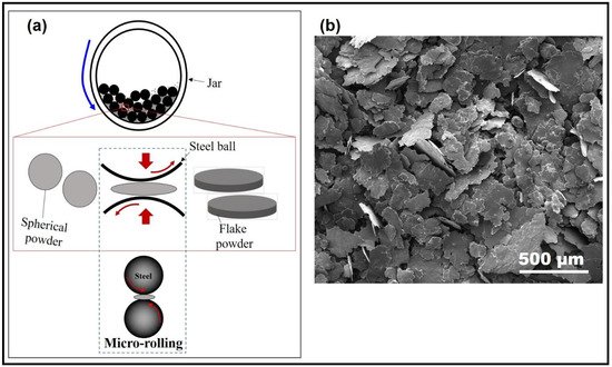
Figure 1. (a) Schematic of micro-rolling process, (b) SEM images of CNT/Al flakes under C-FPM route.
23. Flake Powder Metallurgy via Slurry Blending (FPM-SB)
The strategy of using a slurry-based dispersion process of the reinforcement has emerged as a mighty new route in overcoming the prerequisites needed to produce advanced AMMs [39][69][39,71]. In this technique, the particles’ morphology is modified from three-dimensional spheres to two-dimensional flakes. Subsequently, the surface is modified through organic solutions such as polyvinyl alcohol (PVA) or ethanol. In this way, the flakes can easily attract the second phases onto their surfaces. The produced composite is then compacted and sintered, as illustrated in Figure 2a.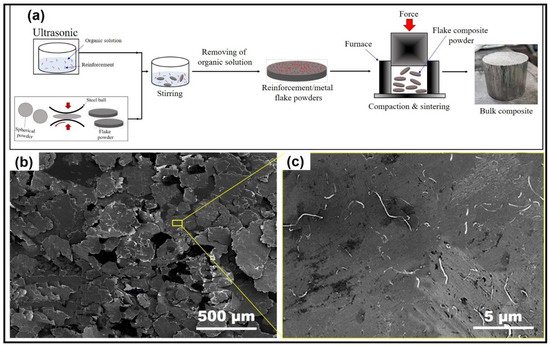
Figure 2. (a) Schematic of slurry-based dispersion process, (b,c) SEM images of CNT/Al flakes under FPM-SB route.
As a matter of fact, the FPM-SB CNT/Al nanocomposite showed tensile stress of 375 MPa with strain to fracture around 12%, very high when compared to corresponding material produced via conventional PM (330 MPa strength and 6% ductility, Figure 3a) [24][26][24,26]. The high-level ordering nanolaminates of flake-shaped building blocks was reported as the key factor in significantly increased tensile strength and ductility when compared with nanocomposites with the same matrix and with non-uniform distribution of CNTs. Moreover, Figure 3b depicts that the advantage of FPM over other methods such as nanoscale dispersion (NSD) [9], low-energy blending (LEB), and others can be obtained through the comparison of the strengthening effects of CNTs®. In fact, an incredible strengthening of the efficiency of CNTs is obtained through FPM thanks to the homogeneous and individual distribution of CNTs in the Al matrix, originating from the high compatibility of Al powders with CNTs [24][70][24,72].
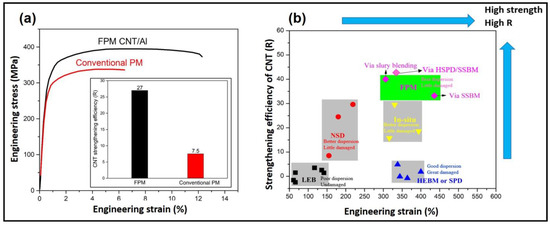
Figure 3. Tensile properties of CNT/Al nanocomposites (a) loading with 1 vol.% CNTs and fabricated by conventional PM and flake PM (inset shows the relevant strengthening efficiencies of CNTs), (b) The strengthening efficiency and tensile strength for CNT/Al composites fabricated by various methods, the data were drawn based on recent reviews [22][24][48][71][72][22,24,48,74,75].
Despite the numerous advantages of FPM via slurry blending, through the application of the abovementioned method to fabricate AMCs with high nano-reinforcement percentages of CNT [3], SiO2 [73], etc., the ductility of the composite also decreased dramatically. Thanks to high nano-reinforcement percentages, various layers of nano-reinforcement can be bonded and overlapped through slurry-based dispersion, even if this leads to difficult bonding between neighboring Al nanoflakes. Hence, the main goal of the FPM processing route for the production of MMCs is the combination of reinforcement dispersion with the structural properties and matrix-second phases bonding.
34. Flake Powder Metallurgy via Shift Speed-Ball Milling (FPM-SSBM)
The correlation between the CNTs distribution, consequent bonding and final mechanical strength of the composites has been the subject of in-depth study by many scientists [35][65][67][74][75][76][77][78][35,65,67,76,77,78,79,80]. Here, the different BM conditions (low- and high-energy) affecting the final properties of AMCs are illustrated in order to optimize the different milling strategies. To this end, recently, Xu et al. [27] proposed a new flake powder metallurgy route via a SSBM strategy. In this strategy, LSBM was applied for very long times in order to obtain aluminum flat flakes with very uniform distribution of reinforcements without damage. The results are compared with those of HSBM in order to produce cold-welded lamellar particles with acceptable CNT/Al bonding and inter-flake bonding, as shown in Figure 4a. Specifically, LSBM allowed for mild ball-to-powder contact and very slow flattening of spherical metal powders into flake-shaped powders. This provided enough time for nano-reinforcements to be optimally dispersed on the surface of metal flakes with low damage to structure integrity of nano-reinforcements, especially carbon-based ones such as CNT or graphene; HSBM showed much more pronounced collisions and cold welding of Al flakes into cake-like particles with a clear laminated structure, as seen in Figure 4b,c, leading to clustered nano-reinforcements within the welded metal particles. In this case, very pronounced damage to reinforcements resulted.
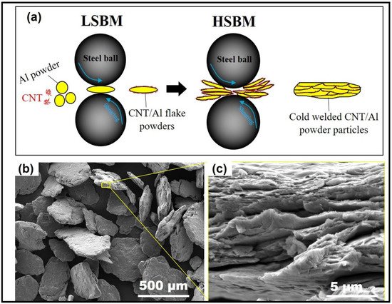
Figure 4. (a) Illustration of co-deformation/dispersion mechanisms of CNT/Al powders during FPM-SSBM, (b,c) SEM images of CNT/Al particles obtained via FPM-SSBM route.
Further developments demonstrate that SSBM, where different powder deformation mechanisms are obtained as a consequence of various milling speeds, produces a high strength of up to 1.5% of CNTs. The strength and ductility levels are much higher compared to sole LSBM or HSBM [27]. As a matter of fact, the optimal combination of reinforcement distribution, structural integrity and matrix-second-phase bonding can be obtained through a new SSBM process known as FPM-SSBM.
Most composites exhibited a strength–ductility dilemma and these data are all placed under a typical ‘‘banana shaped” curve (Figure 5). However, the strength–ductility results of the SSBM route for CNT/Al composite overcome the blue belt in the graph, demonstrating improved mechanical properties. Therefore, FPM-SSBM is a very effective route for this materials’ processing. Comparing previous studies with FPM-SSBM revealed that, with conventional milling processes, it was difficult to fabricate CNT/Al composite with uniform CNT dispersion and good bonding without reducing CNT integrity [70][72]. In contrast, SSBM enhanced the mechanical property of CNT/Al composites by combining the advantages of LSBM, which included mild ball-to-powder collision and slow flattening of spherical Al powders into flakes, with those of HSBM, which included a much stronger collision and cold welding of Al flakes, and avoiding the adverse factors introduced by LSBM and HSBM, which were unhealed insufficient bonding between Al flakes, and many local brittle areas with CNT clusters or forming brittle Al4C3, respectively. Hence, FPM is known as a smart technology of SPD materials based on a bottom-up approach.
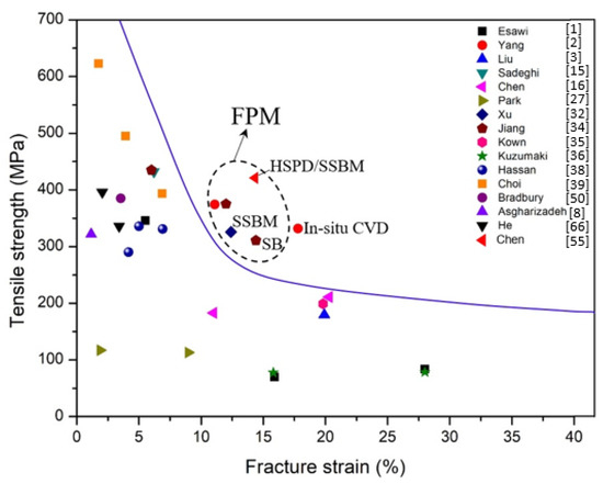
Figure 5. Representative tensile properties of FPM-SSBM CNT/Al composites [27].
45. Flake Powder Metallurgy High-Shear Pre-Dispersion and SSBM (FPM-HSPD/SSBM)
De-agglomeration of CNTs before ball milling results in an optimal solution to gain good reinforcements dispersion. However, this good dispersion is difficult to obtain via the traditional SB route because of the easier re-aggregation of second phases during drying. Presently, many AMCs’ processing routes show some limitations in the reinforcement dispersion, especially in the case of high reinforcement percentages. In addition, as the reinforcement percentage increases, the control of interfacial reactions becomes more difficult [65]. The PM-based methods include high-energy ball milling [19][46][54][19,46,54], flake powder metallurgy [24][34][24,34], liquid-phase ball milling [24][61][24,61], nanoscale dispersion method [9][10][9,10], molecular level mixing [62][63][62,63] and the in-situ formation of CNTs in combination with low-energy ball milling [11][37][64][11,37,64], etc. [65]. Nevertheless, these solutions require energy and time consumption which is incompatible with industrial production. Therefore, pre-dispersion optimized methods are fundamental in this direction [34][52][79][80][34,52,69,82].