Your browser does not fully support modern features. Please upgrade for a smoother experience.
Please note this is a comparison between Version 2 by David Attié and Version 1 by David Attié.
Micromegas (MICRO-MEsh GAseous Structure) detectors have found common use in different applications since their development in 1996 by the group of I. Giomataris and G. Charpak.
- Micromegas
- gaseous detector
- track detector
- X-ray detector
- UV detector
- TPC
- TOF
- Microbulk
- GridPix
- resistive anode
1. Introduction
The Micromegas (Micromesh gaseous structure) particle detector was invented in 1995 by I. Giomataris and collaborators [1]. It is a two-stage parallel plate avalanche chamber with a narrow amplification gap (tens to one or two hundred microns). The gas volume is split between two regions by a thin micromesh, which separates the amplification gap from the drift gap. Figure 1 shows a sketch of the Micromegas working principle.
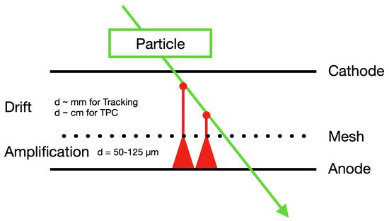
Figure 1. When a particle passes through the Micromegas detector, it ionises several atoms in the conversion volume, and the primary electrons drift to the amplification region. In the amplification region, an electron avalanche is formed.
To preserve a distance between the anode and the grid mesh, spacers from insulating material are used. Initially, fishing lines, 100 μ m in diameter were used, which were soon replaced by pillars fabricated with conventional photo-lithography. In the region above the mesh, called the conversion or ionization region, the primary electrons are produced by the conversion of X-rays or by ionization from a charged track. The field in this region ranges generally from 100 V/cm to 10 kV/cm, fixed by the voltage imposed on an electrode (cathode) closing this volume.
The thickness of this region ranges from a few mm for the detection of normally incident tracks to a few meters in the case of a Time Projection Chamber (TPC) [2,3]. Electrons produced in the conversion gap by the incident particle are drifting toward the mesh and reach the amplification gap due to the funnel shape of the field lines through the mesh holes. In this region, between the mesh and the anode, a high field of several tens of kV/cm induces multiplication to those ionization electrons. The electric field is homogeneous both in the drift and amplification gaps.
Historically parallel plate detectors used an amplification gap on the order of 4 mm. During the development of another detector called the “Hadron Blind Detector” (HBD) [4] in 1991, an improvement of the stability of the structure was noticed when using a narrower gap; however, it proved impossible to go below 1 mm due to the defects of parallelism and the traction of the grid toward the plane of the anode by the strong electric field applied. This improvement effect was later understood and put into the form of a simple mathematical equation: due to the narrow amplification region in Micromegas, the variations of the amplification gap (mechanical defects) are compensated by an inverse variation of the amplification coefficient and, therefore, do not cause fluctuations in the gain of the detector [5]. This is not possible in the case of a large amplification space, such as in traditional parallel plate detectors.
Further improvements and simplifications in the fabrication techniques in the following years led to demonstrating better performance and obtaining outstanding results in the laboratory and in the test beams at the European Laboratory for Particle Physics (CERN): spatial resolution (12 μ m), temporal (<1 ns) and good resistance at counting rates greater than 10 6 s − 1 mm − 2 [6,7]. Thanks to these advances, the detector was adopted by the international scientific community, and today it is widely used in projects by numerous international collaborations [8].
The simple concept of the Micromegas detector has many advantages: a low material budget, only two moderate-voltages suffice to operate it, a fast electron signal, efficient and fast ion collection due to the small gap size, high rate capabilities and low space charge build-up, as well as the absence of a ballistic deficit. The small amplification gap is a key element in Micromegas operation, giving rise to a great performance:
-
Excellent spatial resolution: 12 μ m (Root Mean Square) (RMS) accuracy (limited by the pitch of the micromesh) was achieved in a beam test at CERN, using anode strips with a pitch of 100 μ m and a low diffusion CF 4 /iC 4 H 10 (80:20) mixture [7].
-
A time resolution of 650 ps (RMS) was achieved with the KABES beam spectrometer of the NA48 experiment [9]. Micromegas studies with fast CF 4 -based gases are described in [10]. Recent developments (presented later in Section 9) using Cerenkov light converted in solid photocathodes have shown the capability of reaching a time resolution of 24 ps for Minimum Ionizing Particles (MIPs).
-
An energy resolution of ∼11% (Full Width at Half Maximum) (FWHM) with 5.9 keV photons [7], which is a result close to the limit imposed by statistical fluctuations, showing that the intrinsic fluctuations during the amplifications are small.
2. Micromegas Fabrication Techniques
Micromegas detectors are built using different types of meshes depending on the fabrication technique and the application. We can distinguish three main categories: flat meshes made of thin (4–10 μ m) metallic sheets, where holes are produced by micro-machining procedures (e.g., electroforming, chemical etching, and vaporisation, …) with a typical pitch of 500 Lines Per Inch (LPI).
In the second category, the mesh is made of mechanically woven stainless-steel wires. The typical wire thickness is of 18 μ m, and a maximum mesh thickness of about 30 μ m is achieved by flattening the cross-points of the wires in the mesh. Figure 2 shows a microscopic image of a woven and an electroformed mesh. The third category concerns the cases where the mesh is formed at the same time with the spacers with some specific technique, as is the Microbulk [11] or the InGrid [12] technologies, described later in this section.
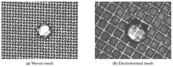
Figure 2. Microscopic pictures of (a) woven inox mesh and (b) electroformed “thinmesh”. Both Micromegas are produced in the bulk technique, and a pillar is shown in the center of the picture.
In the traditional way, Micromegas is obtained by suspending a mesh over the anode strips or pads. Since 2004, several technologies have been developed to attach the mesh structure to the anode plane using higher precision methods and envisaging the transfer of the production to industry. A large step in the direction of the industrial manufacturing of large-size detectors was the development of the “Bulk” Micromegas technology [13].
3. Micromegas as a Tracker in CLAS12 and COMPASS
Micromegas are commonly used for tracking applications. Their low material budget due to their small anode thickness and the gaseous medium compared to solid-state detectors is an advantage. A segmentation of the anode in strips or pads is necessary to preserve the position information of the crossing particles. Micromegas can be used for larger area coverage, and they can be placed in front of a calorimeter due to the relatively small material budget.4. Micromegas in Atlas for HL-LHC Upgrade
Micromegas detectors will be used in the upgrade of the ATLAS detector for the High-Luminosity Large Hadron Collider (HL-LHC) era, where detectors will face an increased particle flux and detector irradiation during operation. Micromegas is a well-suited detector technology for large-area applications with higher particle fluxes due to its rapid evacuation of positive ions. The existing forward inner part of the ATLAS Muon Spectrometer [53], the Small Wheels (SW), are expected to receive irradiation up to 15 kHz cm − 2 , an overly high rate for the existing detectors. An upgrade, called the New Small Wheels (NSW) [15], is foreseen to replace the SWs in 2021–2022. The purpose of the NSW, placed behind the calorimeters and in front of the magnetic toroid, is to track muons and to provide a Level 1 trigger in the endcaps. Micromegas modules (MM) will be installed in the New Small Wheels as precision measurement detector, together with Small Thin Gap Chambers (sTGC) [54,55], used as reference detectors for the L1 trigger, both providing trigger and tracking information. Each NSW consists of 16 wedge-shaped sectors with each sector consisting of 16 detection layers (eight sTGC and eight MM) with the stacking order sTGC-MM-MM-sTGC in the z-direction (see Figure 10).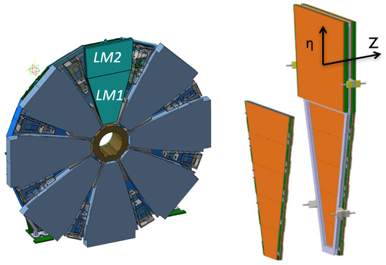
Figure 10. NSW layout with eight large sectors on the HO side (left) and detail of Micromegas module stacking in one sector (right).
-
spatial resolution in the radial ( η ) direction, for all track angles: 100 μ m;
-
spatial resolution on the second coordinate ( Φ ): a few millimeters;
-
track selection: angular resolution of 1 mrad;
-
rate capability up to 15 kHz/cm 2 ; and
-
no radiation aging for a period of 15 years of exploitation.
-
a strip shape and absolute position knowledge of the order or below 40 μ m;
-
an absolute knowledge of all strip positions within Micromegas detectors of the order or below 60 μ m;
-
an absolute external mechanical frame accessible at the level of 40 μ m; and
-
a flatness detector over its full area of the order of or below ∼110 μ m.
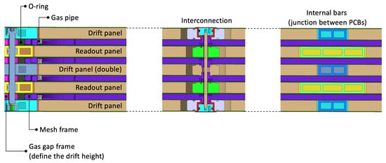
Figure 11. Section of a Micromegas quadruplet with details of the internal components on the edges, at the level of the interconnections and at the junction between PCBs.
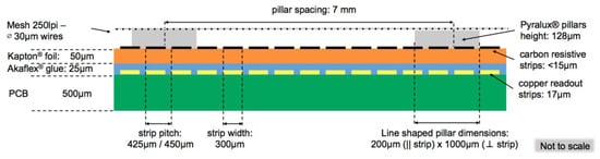
Figure 12. Structure of the RO boards.
Table 1. Readout board parameters.
| Strips per PCB | 1022 |
| Strip width | 300 μ m |
| Strip pitch | 450 μ m |
| Pillar pitch | 7 mm |
| Pillar height | 128 μ m |
5. Micromegas for Muon Tomography
An example for the use of a Micromegas as a tracking detector away from classical HEP experiments is the ScanPyramids project [59]. This project consisted on a scan to study the archaeological heritage of the great pyramids in Egypt using cosmic muons. Cosmic muons are highly energetic particles that have ∼200-times the mass of an electron at rest, resulting in a long radiation length in dense material like concrete.
Muon tomography uses cosmic muons to make non-invasive images from the interior of larger structures, such as buildings, mountains, or pyramids. A part of the muons passing through thick material, such as several meters of concrete, interacts causing a reduction of the particle flux after the object. As structures of different density affect the flux differently, a muon detector can map the density distribution of an object. A three-dimensional image can be produced measuring the same object from different angles.
A portable telescope consisting of four resistive bulk Micromegas with an active area of 50 × 50 cm 2 each and an XY-strip readout is used for the ScanPyramids project (Figure 13). The readout strips are multiplexed to reduce the number of electronic channels and to build a more compact detector unit [60]. A compact and lightweight detector with the given active area was built with Micromegas.
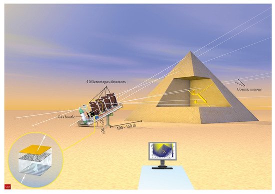
Figure 13. Schematic view of the principle of muography with a Micromegas-based telescope of a pyramid (Illustration by Fabrice Mathé, Les défis du CEA No 210, Septembre 2016). Muon flux density images traced from the telescope position are acquired for different directions. A 3-dimensional image can be produced by combining several images of the same object from different directions.
Bulk Micromegas are robust, and they can operate autonomously for long time periods, even months, as long as a small gas flow maintains the gas quality [61]. For the ScanPyramids project, the Micromegas detectors took data continuously for approximately 100 days to accumulate ∼10 million recorded tracks. A previously unknown void inside of Khufu’s Pyramid was detected by the ScanPyramids project [59]. The muon tomography of the pyramids in the ScanPyramids collaboration additionally used a scintillator hodoscope and nuclear emulsion plates.
6. Micromegas Readout of TPCs
TPCs are very efficient and powerful tools for Particle Identification (PID) through 3D particle tracking in a magnetic field and energy loss measurements. Micro-Pattern Gaseous Detectors (MPGD) are increasingly used in place of Multi Wire Proportional Chambers to readout the TPCs. Micromegas was one of the first MPGD to be deployed on a large scale TPC (T2K 2010, Section 6.1) and proved to be a robust and reliable readout for TPCs due to its simplicity of operation. Micromegas is paticularly suitable to cover the large active surfaces of TPCs with excellent uniformity of performances. It also provides a “natural” ion backflow minimization in the drift region, down to the few per million level [62].
Micromegas TPCs are reliable options for rare event detection due to their background discrimination capabilities, intrinsic low radiopurity materials in the case of the Microbulk technology, energy and time resolution, and stability of operation. In Section 6.4, the detector development in the context of solar axion search will be described in detail, while the use of Micromegas for neutrinoless double-beta decay is presented in Section 6.5. Pertinent initiatives were also carried out for dark matter searches with the TREX-DM experiment [63,64,65] and the MIMAC detector [66].
 Electrons emitted from the photocathode surface experience the same electric field along the same distance to the mesh. The gaseous volume is needed only to amplify the electrons and to induce a readable signal on the anode. A Micromegas-like detector with a grounded mesh between two electric fields with parallel field lines is chosen. A negative voltage is applied to the cathode and a positive voltage to the anode to provide a unidirectional electric field in both regions. With the grounded field, the voltage will only drop until the mesh when a spark occurs. The other region is inversely polarized and stays unaffected by the spark. Additionally, fields can be independently tuned with a grounded mesh, and field scans are easily doable.
7. Micromegas for Neutron Detection
Charged particles and photons can be directly detected with Micromegas detectors, as they ionise gas atoms in the conversion region. Neutrons can also be detected with a Micromegas; however, an additional neutron/charged particle converter is necessary to create primary electrons in the gas. There are different ways of creating a neutron/charged particle converter. It can be realized by a solid target in front of the detector or by additions to the operational gas. Different converter materials are necessary depending on the neutron energy, and a combination of materials can be used to widen the neutron energy range. Next to the additional converter, all typical benefits of a Micromegas, such as the low material budget, the high-rate capability, and the precise tracking and energy resolution are conserved.8. Micromegas for UV Detection
Micromegas can be used as a UV photo-detector. Similar to the detection of neutrons, a photon/charged particle converter needs to be coupled to a Micromegas. The most common method of converting photons to electrons is the photoelectric effect. Photons with sufficient energy interact with electrons bounded to an atomic orbital or a lattice band. Photons can transfer enough energy to the electrons and remove them from the bound state. Those free electrons are further amplified in the Micromegas with the same mechanism as any other primary electron.9. Micromegas for Precise Timing
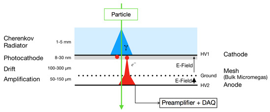
A MIP forms multiple ionization clusters when passing through the drift region of a Micromegas detector. The number of clusters and their locations are distributed according to the average ionization length of the particle in the given gaseous medium. The location of the clusters may vary around 100 μ m for a MIP affecting the distance of the last cluster to the mesh. The gas type and the electric field limit the drift velocity of the electrons. The spread of the electrons during the primary ionization process and their diffusion in gas while drifting toward the micromesh result in a time jitter of several nanoseconds for the electrons when reaching the mesh. As a result, a Micromegas can not achieve a sub-nanosecond time resolution for vertex separation of MIPs as demanded at future HEP experiments [114]. PICOSEC-Micromegas is an R&D project that was initiated in order to overcome this limitation in time resolution by introducing a new detection concept for Micromegas detectors [115]. Figure 26 illustrates this concept. A Cherenkov radiator [116] and a photocathode are placed in front of the gaseous volume. The passage of a charged particle through the Cherenkov radiator produces UV photons, which are then absorbed in the photocathode, and primary electrons are created on the bottom surface of the photocathode. These electrons are subsequently preamplified and then amplified in the two high-field stages, thereby, inducing a signal that is measured between the anode and the mesh.Figure 26. The PICOSEC-Micromegas detection concept, described in detail in the text.PICOSEC-Micromegas sketch.