1. Introduction
It is well known that the stable allotrope of carbon at ambient pressure and room temperature is graphite. As can be seen in the carbon phase diagram of
It is well known that the stable allotrope of carbon at ambient pressure and room temperature is graphite. As can be seen in the carbon phase diagram of
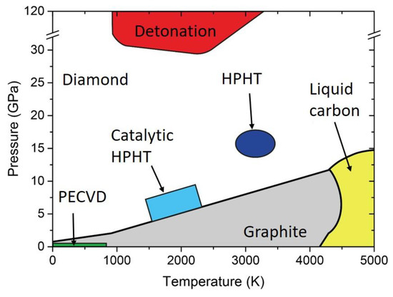
, diamond requires extreme conditions of temperature and pressure to be formed. For instance, natural diamond may be formed in the Earth’s mantle, 140−200 km below the surface [1], where the temperature and pressure are in the range of 900−1400 °C and 4.5−6 GPa, respectively [2]. Once the diamond phase is formed, the transition back to graphite at ambient conditions is avoided by the high energy barrier for phase transition. Indeed, even if graphite is thermodynamically favored (energy difference of 0.02 eV per atom between diamond and graphite), a 0.4 eV energy barrier must be overcome to move from sp
, diamond requires extreme conditions of temperature and pressure to be formed. For instance, natural diamond may be formed in the Earth’s mantle, 140−200 km below the surface [26], where the temperature and pressure are in the range of 900−1400 °C and 4.5−6 GPa, respectively [27]. Once the diamond phase is formed, the transition back to graphite at ambient conditions is avoided by the high energy barrier for phase transition. Indeed, even if graphite is thermodynamically favored (energy difference of 0.02 eV per atom between diamond and graphite), a 0.4 eV energy barrier must be overcome to move from sp 2
to sp
3 chemical bonds. This makes diamond a metastable phase, as it is thermodynamically unstable, but the transition kinetics to graphite is prohibitive. Currently, many different methods for artificial synthesis of NDs are available [3]. The three main techniques commercially available are described: detonation, chemical vapor deposition (CVD), and milling of high-pressure, high-temperature (HPHT) micro-sized diamonds.
chemical bonds. This makes diamond a metastable phase, as it is thermodynamically unstable, but the transition kinetics to graphite is prohibitive. Currently, many different methods for artificial synthesis of NDs are available [1]. In the following sections, the three main techniques commercially available are described: detonation, chemical vapor deposition (CVD), and milling of high-pressure, high-temperature (HPHT) micro-sized diamonds.
Figure 1.
Carbon phase diagram indicating graphite (grey), diamond (white), and liquid (yellow). In addition, pressure-temperature conditions reached with different synthesis technique are indicated. HPHT: high pressure, high temperature. PECVD: Plasma Enhanced Chemical Vapor Deposition.
2. Classification
2.1. Detonation Synthesis
Detonation Synthesis
In detonation synthesis, the energy of an explosion is used to drive the diamond phase formation [4]. In a closed metallic chamber, explosives with a negative oxygen balance are detonated; usually a mixture of 60% TNT (C
In detonation synthesis, the energy of an explosion is used to drive the diamond phase formation [28]. In a closed metallic chamber, explosives with a negative oxygen balance are detonated; usually a mixture of 60% TNT (C 6
H
2
(NO
2
)CH
3
) and 40% hexogen (C
3
H
6
N
6
O
6
) is employed (
) [3]. The carbon atoms that eventually form the NDs are provided either by the molecules of the explosives or by precursor graphite put inside the detonation chamber. The synthesis is called “dry” or “wet” when the chamber is filled with a gas (N
) [1]. The carbon atoms that eventually form the NDs are provided either by the molecules of the explosives or by precursor graphite put inside the detonation chamber. The synthesis is called “dry” or “wet” when the chamber is filled with a gas (N 2
, Ar, CO
2) or with water (ice), respectively, that act as coolants. The cooling media play an important role in the carbon yield, which is usually around 10% of the explosive weight [5]. The process leading to NDs formation is schematized in
) or with water (ice), respectively, that act as coolants. The cooling media play an important role in the carbon yield, which is usually around 10% of the explosive weight [29]. The process leading to NDs formation is schematized in . After detonation, the carbon atoms released during the explosive molecule’s dissociation condense and crystallize into nanoclusters [6]. The pressure/temperature increase (
. After detonation, the carbon atoms released during the explosive molecule’s dissociation condense and crystallize into nanoclusters [30]. The pressure/temperature increase ( ) reached in the chamber during the detonation leads to crystallization of the carbon nanoclusters into diamond phase. Finally, the formed NDs grow and agglomerate, resulting in NDs of size 4−5 nm. The main drawback of this technique is that the resulting sample, called detonation soot, must be purified to remove contaminants. Indeed, detonation soot is not only made of diamond phase, but also of non-diamond carbon (25–85 wt %) and metals coming from the wall of the chamber (1−8 wt %) [7]. To remove the impurities, cleaning of the detonation soot in a strong acid environment (usually a mixture of HNO
) reached in the chamber during the detonation leads to crystallization of the carbon nanoclusters into diamond phase. Finally, the formed NDs grow and agglomerate, resulting in NDs of size 4−5 nm. The main drawback of this technique is that the resulting sample, called detonation soot, must be purified to remove contaminants. Indeed, detonation soot is not only made of diamond phase, but also of non-diamond carbon (25–85 wt %) and metals coming from the wall of the chamber (1−8 wt %) [31]. To remove the impurities, cleaning of the detonation soot in a strong acid environment (usually a mixture of HNO 3
/H
2
SO
4
/HClO
4) is required [4], which is a dangerous and expensive process. Another problem is NDs agglomeration occurring during synthesis, where NDs clusters of several hundreds of nanometers are obtained. To isolate the single 4−5 nm sized NDs, milling with ceramic microbeads (that again introduces contaminants) or ultrasonic disintegration are the standard de-aggregation methods [8].
) is required [28], which is a dangerous and expensive process. Another problem is NDs agglomeration occurring during synthesis, where NDs clusters of several hundreds of nanometers are obtained. To isolate the single 4−5 nm sized NDs, milling with ceramic microbeads (that again introduces contaminants) or ultrasonic disintegration are the standard de-aggregation methods [32].
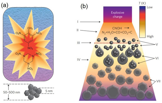
Figure 2.
(
a
) Detonation process. A mixture of 60% TNT (C
6
H
2
(NO
2
)CH
3
) and 40% hexogen (C
3
H
6
N
6
O
6
) is detonated inside a metallic chamber filled either with water (liquid or ice) or gas (an atmosphere of N
2
, Ar, or CO
2
). Then, 4–5 nm sized nanodiamonds (NDs) agglomerated into sub-micrometer clusters are obtained. (
b) Schematics of NDs synthesis upon shock wave propagation. The detonation (I) leads to chemical dissociation of the carbon precursor (II), which can be the explosive molecules or graphite. The dashed line (III) represents the region where the pressure required to form the diamond phase is reached. The detonation products expand (IV), and the carbon atoms condense and crystallize (V) to form nanoclusters (VI). Finally, NDs crystallize, starting from carbon nanoclusters, grow, and agglomerate (VII). Reproduced with permission from [3], Springer, 2012.
) Schematics of NDs synthesis upon shock wave propagation. The detonation (I) leads to chemical dissociation of the carbon precursor (II), which can be the explosive molecules or graphite. The dashed line (III) represents the region where the pressure required to form the diamond phase is reached. The detonation products expand (IV), and the carbon atoms condense and crystallize (V) to form nanoclusters (VI). Finally, NDs crystallize, starting from carbon nanoclusters, grow, and agglomerate (VII). Reproduced with permission from [1], Springer, 2012.
2.2. Chemical Vapor Deposition (CVD)
Chemical Vapor Deposition (CVD)
Chemical vapor deposition is one of the most popular methods for the deposition of thin film, and it has been used for the synthesis of nanocrystalline diamond film [9]. In detail, the deposition of carbon atoms occurs during decomposition of a gas mixture with a carbon containing species, usually methane CH
Chemical vapor deposition is one of the most popular methods for the deposition of thin film, and it has been used for the synthesis of nanocrystalline diamond film [33]. In detail, the deposition of carbon atoms occurs during decomposition of a gas mixture with a carbon containing species, usually methane CH 4
, in an excess of hydrogen. The gas phase is decomposed by using a hot filament or a microwave plasma to form radicals such as H
•
and CH
3•, which are essential for diamond growth. The ND film forms on a substrate, typically a silicon wafer coated with a micrometer sized diamond powder acting as a seed for ND nucleation [9], and eventually forms a continuous film. The typical set-up [10] for CVD synthesis is reported in
, which are essential for diamond growth. The ND film forms on a substrate, typically a silicon wafer coated with a micrometer sized diamond powder acting as a seed for ND nucleation [33], and eventually forms a continuous film. The typical set-up [34] for CVD synthesis is reported in a. The size of the grains composing the film ranges to tens of micron down to a few nanometers, depending on CH
4
/H
2 relative concentration [11].
relative concentration [35].
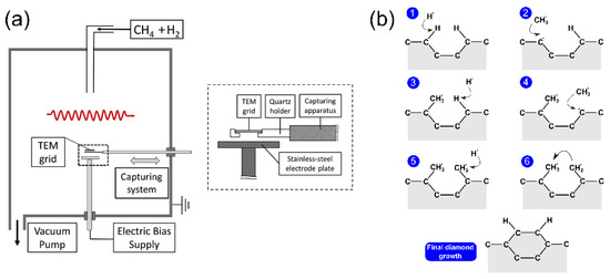
Figure 3.
(
a
) Experimental setup for chemical vapor deposition (CVD) synthesis. The hot filament is required to dissociate the gas phase (CH
4
/H
2
mixture) into radicals, whereas the electrode plate is used to attract those radicals (mainly H
•
and CH
•) toward the substrate. Reproduced with permission from [10], Elsevier, 2016. (
) toward the substrate. Reproduced with permission from [34], Elsevier, 2016. ( b
) Schematization of the standard growth mechanism of nanocrystalline diamond film during CVD synthesis.
A weak concentration of CH
4
produces microcrystalline diamonds, whereas a high value of the CH
4
/H
2
ratio decreases grain size to the order of tens of nanometers for 1−5% CH
4
/H
2. The standard diamond growth mechanism [11] is schematized in
. The standard diamond growth mechanism [35] is schematized in b. Carbon atoms at the surface of diamond seeds are left with dangling bonds after hydrogen abstraction by H
•
radicals. These bonds are then filled by CH
3•
molecules. When this process takes place in two adjacent sites, the new carbons can bond together, and finally be locked into the diamond lattice.
2.3. Milling of High-Pressure, High-Temperature (HPHT) Microdiamonds
Milling of High-Pressure, High-Temperature (HPHT) Microdiamonds
The HPHT synthesis technique resembles the natural process of diamond formation, where a carbon precursor, usually graphite, is brought to a state of high pressure and high temperature. Inside a chamber, the temperature is brought to ~2000 °C and a set of anvils increases the pressure up to several GPa [12]. This technique allows for the formation of bulk or microdiamonds, which must be milled to obtain NDs [13]. The milling process does not allow for good control of nanoparticle size and shape [14], so additional work-up is required. For instance, an acid treatment to remove the contaminants coming from the milling process or centrifugation and filtration to isolate NDs with a narrower size distribution.
The HPHT synthesis technique resembles the natural process of diamond formation, where a carbon precursor, usually graphite, is brought to a state of high pressure and high temperature. Inside a chamber, the temperature is brought to ~2000 °C and a set of anvils increases the pressure up to several GPa [36]. This technique allows for the formation of bulk or microdiamonds, which must be milled to obtain NDs [21]. The milling process does not allow for good control of nanoparticle size and shape [37], so additional work-up is required. For instance, an acid treatment to remove the contaminants coming from the milling process or centrifugation and filtration to isolate NDs with a narrower size distribution.
2.4. Pulsed Laser Ablation
Pulsed Laser Ablation
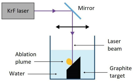
Starting from the pioneering work of Yang et al. [15], PLA has become a viable method for the synthesis of NDs. A standard PLA experimental setup for NDs is given in
Starting from the pioneering work of Yang et al. [38], PLA has become a viable method for the synthesis of NDs. A standard PLA experimental setup for NDs is given in . The laser beam is focused on the top surface of a graphite target that is immersed in a liquid, which is typically water, but NDs production has been observed in other liquid environments, such as cyclohehexane [16]. A pulsed laser is used in order to release an extremely high power on the target; usually, laser pulses in the ns region with energies in the order of 100 mJ, for a final power density of up to GW cm
. The laser beam is focused on the top surface of a graphite target that is immersed in a liquid, which is typically water, but NDs production has been observed in other liquid environments, such as cyclohehexane [39]. A pulsed laser is used in order to release an extremely high power on the target; usually, laser pulses in the ns region with energies in the order of 100 mJ, for a final power density of up to GW cm −2
, are employed.
Figure 4. Experimental setup of pulsed laser ablation in liquid. Reproduced with permission from [17], Springer, 2018.
Experimental setup of pulsed laser ablation in liquid. Reproduced with permission from [40], Springer, 2018.
In pulsed laser ablation, the water plays a double role; it is a medium, where nanoparticles are suspended and collected during ablation, and it confines the ablation plume, which favors the diamond-phase formation. Indeed, the presence of a confining layer in front of the target is a fundamental aspect of the transition from sp
2
carbon atoms of graphite to sp
3 hybridization of the diamond phase. The details of the formation mechanism are provided in [17][18]. The synthesis of NDs upon the PLA of graphite in water occurs in three steps:
hybridization of the diamond phase. The details of the formation mechanism are provided in [40,41]. The synthesis of NDs upon the PLA of graphite in water occurs in three steps:
-
The absorption of the high power laser pulse induces melting of the graphite surface. As the laser energy is deposited in a short timescale, the target surface rapidly becomes a superheated liquid. When the temperature of this liquid reaches a value of about 90% of the critical temperature, T
C, a process known as phase explosion occurs
[19][25], leading to the ejection of nanodroplets
[20] [42] that eventually turn into nanoparticles after solidification.
-
Strong vaporization of the graphite target and phase explosion lead to the emission of a plasma plume containing the ablated material; inside the liquid, a state of extreme thermodynamic conditions of temperature and pressure is created, of 5000–6000 K
[21][43] and 2–4 GPa
[19][22][41,44], respectively.
-
The last step concerns the cooling of the ablation plume. Due to the confinement effect, the ablation plume dissipates excess heat very efficiently through collisional cooling with the liquid molecules, resulting in a short quenching time. The fast cooling rate is the most peculiar characteristic of laser ablation in liquid, which can be in the order of 10
10–10
11 K s
−1 [23][45]. This strong and fast reduction in the temperature is enough to produce the carbon nanodroplets in an undercooling regime in a few nanoseconds. In this condition of undercooling, NDs form as a metastable phase, starting from the nanodroplets expelled by phase explosion. The transition to the thermodynamic stable allotrope of carbon, namely graphite, is prevented by the rapid quenching; the metastable phase is literally frozen under the undercooling action.
shows the characterization of NDs produced through the PLA of graphite in water as reported in [18].
shows the characterization of NDs produced through the PLA of graphite in water as reported in [40].
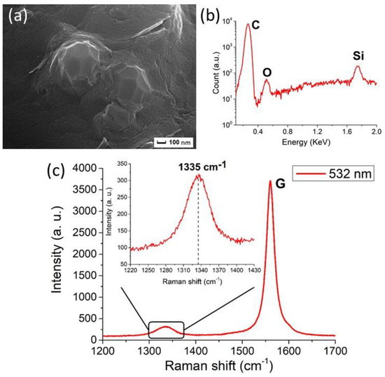
Figure 5.
Characterization of the NDs from graphite ablation in water. (
a
) Typical Scanning Electron Microscopy (SEM) image, after removal of the non-diamond phase of carbon, showing clustered nanoparticles of about 100 nm size. (
b
) Energy-dispersive X-ray Spectroscopy (EDXS) spectrum of the nanoparticles. The carbon peak is detected at 0.27 keV. Moreover, the peaks of silicon at 1.74 keV and of oxygen at 0.52 keV are observed. They come from the substrate on which the particles are deposited and from the oxidized surface layers of the ablated powders, respectively. (
c
) Raman spectrum (obtained under 532 nm excitation wavelength) of purified particles. The main peak at 1580 cm
−1
is the graphite G peak, while the peak at 1335 cm
−1 (shown in detail in the inset) is attributed to compressively-strained NDs. Reproduced with permission from [18], Springer, 2018.
(shown in detail in the inset) is attributed to compressively-strained NDs. Reproduced with permission from [40], Springer, 2018.
PLA for NDs synthesis presents some advantages compared to the standard production processes, such as HPHT or detonation. For instance, the sample is not contaminated by metallic impurities that require harsh chemical purification. NDs produced by laser ablation only require removal of the graphitic shell covering the nanoparticles. Indeed, when the temperature and pressure conditions inside the ablation plume are no longer the ones required for diamond phase formation, a sp
2
shell forms around the NDs. An efficient and simple way to remove the shell was found by Osawa Osswald [
31
]; it consists of air oxidation at ~400 °C. Furthermore, the main advantage of PLA for NDs production is the possibility of achieving diamond phase formation with a simple and cheap experimental apparatus, and performing the synthesis process at ambient pressure and temperature conditions.
2.5. Nanodiamond Purification Methods
Nanodiamond Purification Methods
Work-up and post-processing procedures aimed at purifying reaction products are often a critical step in the synthesis of NDs. Several methodologies have been developed to cope with the two most common and abundant contaminants: other forms of carbon (mostly graphitic) and metals and their oxides.
For the carbon contaminants, the common principle underlying purification is selective oxidation, exploiting the higher reactivity of sp
2
carbon with respect to the sp
3 carbon of the diamond phase. Examples are the above mentioned oxidation in air reported by Osawa Osswald [7], which was further investigated in a subsequent paper [24] where selectivity towards sp
carbon of the diamond phase. Examples are the above mentioned oxidation in air reported by Osawa Osswald [31], which was further investigated in a subsequent paper [46] where selectivity towards sp 2
carbon was achieved by keeping the temperature in the range of 400–430 °C. This procedure provides a simple and effective solution for the case of PLA NDs where, even though metallic impurities are avoided, the sp
2 carbon fraction can be so high as to actually be the main reaction product. A similar method, but employing boric anhydride to enhance selectivity, was also reported [25]. Another route that has been explored is oxidation with ozone-enriched air [26][27][28], though these procedures require significantly more complex equipment.
carbon fraction can be so high as to actually be the main reaction product. A similar method, but employing boric anhydride to enhance selectivity, was also reported [47]. Another route that has been explored is oxidation with ozone-enriched air [48,49,50], though these procedures require significantly more complex equipment.
Liquid-phase oxidation reactions are by far the most commonly employed procedures. These generally require strong acids, which provide the additional advantage of also removing some metal-based impurities. Examples include HClO
4
, concentrated HNO
3
, H
2
SO
4
alone and in combination with HNO
3
, HCl in combination with HNO
3, and HF [5][29][30][31]. These treatments require temperatures from 80 °C to more than 200 °C, thus, specialized equipment is needed that adds to the complexity and cost. Yet, this is necessary, especially in the case of detonation NDs, where metal-based impurities are present in significant quantities, coming from the equipment involved in these processes, such as steel detonation chambers. For a comprehensive review, though it is focused on detonation NDs, the reader should consider Aleksenskii [32].
, and HF [29,51,52,53]. These treatments require temperatures from 80 °C to more than 200 °C, thus, specialized equipment is needed that adds to the complexity and cost. Yet, this is necessary, especially in the case of detonation NDs, where metal-based impurities are present in significant quantities, coming from the equipment involved in these processes, such as steel detonation chambers. For a comprehensive review, though it is focused on detonation NDs, the reader should consider Aleksenskii [54].
2.6. Synthesis of Nitrogen-Vacancy (NV)Centers-Enriched Nanodiamonds (NDs)
Synthesis of Nitrogen-Vacancy (NV)Centers-Enriched Nanodiamonds (NDs)
Recently, Reineck et al. [33] reported the observation of NV
Recently, Reineck et al. [55] reported the observation of NV − emissions from unprocessed detonation NDs, with a brightness comparable to what is obtained with highly processed fluorescent 100 nm HPHT NDs. Moreover, diamond CVD synthesis of highly-oriented NV centers was reported [34], with the possibility of crushing fluorescent bulk diamond into NDs [35].
emissions from unprocessed detonation NDs, with a brightness comparable to what is obtained with highly processed fluorescent 100 nm HPHT NDs. Moreover, diamond CVD synthesis of highly-oriented NV centers was reported [56], with the possibility of crushing fluorescent bulk diamond into NDs [57].
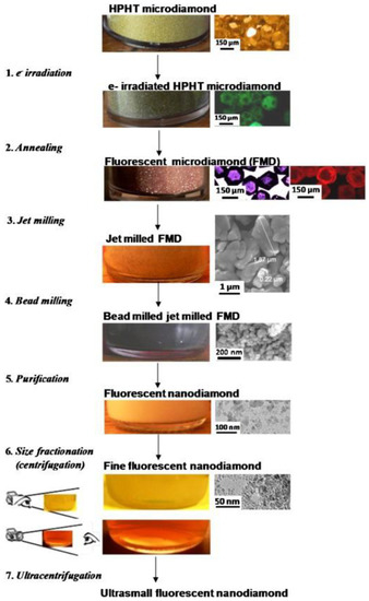
Despite that, the standard way to produce NV-centers-enriched NDs is a complex, multi-step, and expensive process. Synthetic HPHT diamonds typically contain 100 ppm of nitrogen atoms as an impurity in the diamond structure [36] and to form NV centers, vacancies are created in the lattice by high-energy particle irradiation (electrons, protons, He+) followed by a vacuum annealing at 700–1000 °C [37]. The role of the annealing is to increase the mobility of the nitrogen atoms inside the lattice, which are then trapped by the carbon vacancies to form NVs. One could directly irradiate NDs to increase the NV-fluorescence, but it has been proven by density functional theory [38] and Monte Carlo simulations [39] that NV concentration increases non-linearly with crystal size. In particular, the probability of forming NV centers in 5 nm sized NDs is 4.5 and 25 times lower compared to 20 and 55 nm NDs, respectively [39]. Thus, it is more efficient to increase NV concentration in micro-sized diamonds and then reduce their size to obtain fluorescent NDs. This was done by Boudou et al. [40], in what has become the standard fluorescent NDs synthesis technique. The procedure is shown in
Despite that, the standard way to produce NV-centers-enriched NDs is a complex, multi-step, and expensive process. Synthetic HPHT diamonds typically contain 100 ppm of nitrogen atoms as an impurity in the diamond structure [58] and to form NV centers, vacancies are created in the lattice by high-energy particle irradiation (electrons, protons, He+) followed by a vacuum annealing at 700–1000 °C [59]. The role of the annealing is to increase the mobility of the nitrogen atoms inside the lattice, which are then trapped by the carbon vacancies to form NVs. One could directly irradiate NDs to increase the NV-fluorescence, but it has been proven by density functional theory [60] and Monte Carlo simulations [61] that NV concentration increases non-linearly with crystal size. In particular, the probability of forming NV centers in 5 nm sized NDs is 4.5 and 25 times lower compared to 20 and 55 nm NDs, respectively [61]. Thus, it is more efficient to increase NV concentration in micro-sized diamonds and then reduce their size to obtain fluorescent NDs. This was done by Boudou et al. [23], in what has become the standard fluorescent NDs synthesis technique. The procedure is shown in . The starting material is HPHT-synthesized microdiamonds that are then irradiated with a 10 MeV electron beam to form vacancies. The following step is annealing at 750 °C to form fluorescent microdiamonds. The next step is the reduction of diamond size, achieved by nitrogen jet milling and ball milling to obtain NDs with a crystal size smaller than 10 nm. For bioimaging, which is the main field of application for fluorescent NDs, the number of NV centers should be as high as possible. For this reason, only HPHT diamonds that contain a relevant amount of nitrogen impurities are used. In contrast, CVD diamond films contain a very small number of nitrogen atoms [41]. Consequently, highly fluorescent NDs are not produced by this mechanism; rather CVD is used to produce nanocrystalline diamond films with single NV centers, suitable for quantum information technologies.
. The starting material is HPHT-synthesized microdiamonds that are then irradiated with a 10 MeV electron beam to form vacancies. The following step is annealing at 750 °C to form fluorescent microdiamonds. The next step is the reduction of diamond size, achieved by nitrogen jet milling and ball milling to obtain NDs with a crystal size smaller than 10 nm. For bioimaging, which is the main field of application for fluorescent NDs, the number of NV centers should be as high as possible. For this reason, only HPHT diamonds that contain a relevant amount of nitrogen impurities are used. In contrast, CVD diamond films contain a very small number of nitrogen atoms [62]. Consequently, highly fluorescent NDs are not produced by this mechanism; rather CVD is used to produce nanocrystalline diamond films with single NV centers, suitable for quantum information technologies.
Figure 6.
Nitrogen-vacancy
(NV)-enriched NDs preparation. Reproduced with permission from [40], Elsevier, 2013.
NV)-enriched NDs preparation. Reproduced with permission from [23], Elsevier, 2013.
2.7. Fluorescent NDs Synthesis by Pulsed Laser Ablation
Fluorescent NDs Synthesis by Pulsed Laser Ablation
PLA has been demonstrated to be a promising process for the direct synthesis of NV-enriched NDs. Narayan et al. [42] achieved synthesis of NV-doped diamond in the form of single-crystal nanodiamonds, nanoneedles, microneedles, and thin films by pulsed laser irradiation of N-doped carbon film. Diamond phase formation is obtained through conversion of the sp
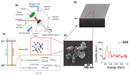
PLA has been demonstrated to be a promising process for the direct synthesis of NV-enriched NDs. Narayan et al. [63] achieved synthesis of NV-doped diamond in the form of single-crystal nanodiamonds, nanoneedles, microneedles, and thin films by pulsed laser irradiation of N-doped carbon film. Diamond phase formation is obtained through conversion of the sp 2 carbon atoms through rapid melting in a super undercooled state and consequent quenching at ambient temperatures and pressures in air. Recently, we demonstrated direct synthesis of NV-centers-enriched NDs through the PLA of graphite in two different nitrogen-containing media: controlled nitrogen atmosphere [43] and liquid nitrogen [44]. In the first case, graphite is laser ablated inside a vacuum chamber filled with 1 Pa of nitrogen gas, and the ablated material deposits onto a silicon substrate. The resulting sample is a diamond-like carbon (DLC) film embedded with the fluorescent NDs (
carbon atoms through rapid melting in a super undercooled state and consequent quenching at ambient temperatures and pressures in air. Recently, we demonstrated direct synthesis of NV-centers-enriched NDs through the PLA of graphite in two different nitrogen-containing media: controlled nitrogen atmosphere [64] and liquid nitrogen [65]. In the first case, graphite is laser ablated inside a vacuum chamber filled with 1 Pa of nitrogen gas, and the ablated material deposits onto a silicon substrate. The resulting sample is a diamond-like carbon (DLC) film embedded with the fluorescent NDs ( ).
Figure 7.
(
a
) Experimental setup of pulsed laser ablation (PLA). (
b
) SEM image of the synthesized sample: on the Si substrate a thin diamond-like carbon (DLC) film is deposited over which NDs are dispersed. (
c
) NV
−
center energy levels. When the NV is excited by using a green laser (green arrow), it can relax either radiatively (red arrow) or non-radiatively (yellow dotted arrow). The effect of the lattice strain, both in its parallel and perpendicular components with respect to the NV axis, on the degenerated
ms
= 1 spin states is represented (see text for details). In the red box: scheme of diamond crystal structure with an NV center, consisting of a nitrogen atom (blue sphere) and a nearest-neighbor carbon-vacancy (yellow circle) along the (111) direction. (
d) Left-hand side: SEM image of one microparticle deposited on the DLC film, consisting of clustered C-nanoparticles with sizes below 50 nm. Right-hand side: corresponding EDXS spectrum. The carbon and nitrogen peaks are detected at, respectively, 0.27 and 0.38 KeV, indicating that the nitrogen is contained inside the nanoparticles’ cluster. In addition, the silicon peak from the Si substrate was detected at 1.74 KeV (not shown). Reproduced with permission from [43], Royal Society of Chemistry, 2018.
) Left-hand side: SEM image of one microparticle deposited on the DLC film, consisting of clustered C-nanoparticles with sizes below 50 nm. Right-hand side: corresponding EDXS spectrum. The carbon and nitrogen peaks are detected at, respectively, 0.27 and 0.38 KeV, indicating that the nitrogen is contained inside the nanoparticles’ cluster. In addition, the silicon peak from the Si substrate was detected at 1.74 KeV (not shown). Reproduced with permission from [64], Royal Society of Chemistry, 2018.
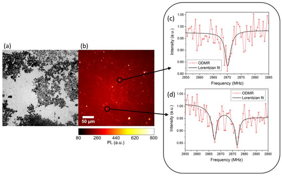
In the case of ablation in liquid nitrogen, the NDs are directly dispersed into the liquid medium. In both cases, NDs show intense native photoluminescence (PL) without the need of post-synthesis thermal activation or additional procedures. Proof of NV centers formation is obtained through optically detected magnetic resonance (ODMR), reported in
, for synthesis in liquid nitrogen.
Figure 8.
(
a
) Wide field optical image and (
b
) relative photoluminescence (PL) image. (
c
,
d
) Typical ODMR spectra obtained from the bright spot of (
b
), confirming the Nitrogen-Vacancy (NV) origin of the collected PL. The intensity reduction at 2.87 GHz is evident in (
c
), while in (
d
) a double resonance is observed due to strain of the NDs hosting the NV centers and removing the degeneracy of the
ms = ±1 states. Reproduced with permission from [44], Elsevier, 2019.
= ±1 states. Reproduced with permission from [65], Elsevier, 2019.
The mechanism responsible for ND formation is the same reported . The whole graphite–liquid–diamond transition is represented by the purple arrow in the carbon phase diagram [18] in
The mechanism responsible for ND formation is the same reported in Section 2.4. The whole graphite–liquid–diamond transition is represented by the purple arrow in the carbon phase diagram [41] in a. The tilted red lines indicate the region where undercooled liquid carbon and metastable diamond coexist, referred to as a “diamond-like” liquid [45]. The transition to diamond phase occurs because in this thermodynamic condition, the energy barrier for diamond formation is lower than that for graphite formation [46]. It is important to note the presence of atomic nitrogen, which is required for NV-centers formation. The energy of the atoms, ions (from C
a. The tilted red lines indicate the region where undercooled liquid carbon and metastable diamond coexist, referred to as a “diamond-like” liquid [66]. The transition to diamond phase occurs because in this thermodynamic condition, the energy barrier for diamond formation is lower than that for graphite formation [67]. It is important to note the presence of atomic nitrogen, which is required for NV-centers formation. The energy of the atoms, ions (from C +
to C
4+), and electrons leaving the laser ablated target can be higher than 100 eV for the typical laser fluence used [47]. This energy is enough to break the N
), and electrons leaving the laser ablated target can be higher than 100 eV for the typical laser fluence used [68]. This energy is enough to break the N 2
molecules, having a bond dissociation energy at room temperature of 9.79 eV. Thus, the ablated energetic species can easily break N
2
molecules, and single N atoms may be trapped inside the nanodroplets expelled from the graphite target. Interestingly, we performed a comparison between these two methods (ablation of graphite in gas and liquid nitrogen) in term of the total PL emission of the produced sample (
b,c).
Figure 9.
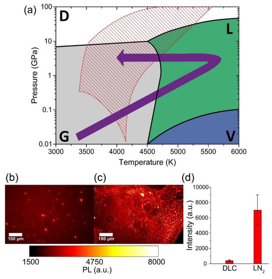
a
) Carbon phase diagram. Stability regions of diamond (D), graphite (G), vapor (V), and liquid carbon (L) are indicated, respectively, in white, grey, blue, and green. The purple arrow shows the graphite–liquid–diamond transition used to explain ND formation under pulsed laser irradiation of graphite in LN
2. The tilted red lines show the region known as “diamond-like liquid” [9], where undercooled liquid carbon and metastable diamond coexist. Typical PL wide-field images of NDs synthesized by Pulsed Laser Deposition (PLD) in nitrogen atmosphere (
. The tilted red lines show the region known as “diamond-like liquid” [33], where undercooled liquid carbon and metastable diamond coexist. Typical PL wide-field images of NDs synthesized by Pulsed Laser Deposition (PLD) in nitrogen atmosphere ( b
) and by PLA in liquid nitrogen (
c
d
) PL strength comparison between the two samples, obtained by integrating the intensity of the whole PL image after background subtraction: LN
2
-NDs show a more than 10× higher emission compared to Diamond-like Carbon (DLC)-embedded NDs. The error bars of (
d) are given by the standard deviation of the different integrated images. Reproduced with permission from [44], Elsevier, 2019.
) are given by the standard deviation of the different integrated images. Reproduced with permission from [65], Elsevier, 2019.
The results, shown in
The results, shown in
d, prove that the LN
2
-NDs present a PL emission intensity (7000 ± 2000 a.u.) that is more than one order of magnitude higher with respect to DLC-NDs (400 ± 100 a.u.). The explanation of this larger NV-enriched ND production efficiency can be related to the different conditions attained inside the ablation plume. In particular, a strong sp
2 contamination of the NV-enriched NDs surface is observed for laser ablation in a gaseous environment [44] due to both lower pressure and smaller cooling rates achieved in the ablation plume.
contamination of the NV-enriched NDs surface is observed for laser ablation in a gaseous environment [65] due to both lower pressure and smaller cooling rates achieved in the ablation plume.