Your browser does not fully support modern features. Please upgrade for a smoother experience.
Please note this is a comparison between Version 1 by Julia Yang and Version 2 by Rita Xu.
Layered intercalation compounds are the dominant cathode materials for rechargeable Li-ion batteries. In this review, we discuss the topology of the layered structure and explain how the structure (1) sets the voltage slope trends among various alkali ions, (2) is critically limited to certain transition metals due to their electronic structure, and (3) controls the alkali diffusion mechanism.
- layered oxide cathodes
- alkali–alkali interactions
- electronic structure
- Li diffusion
1. Introduction to the O3 Structure
Rechargeable Li-ion batteries have enabled a wireless revolution and are currently the dominant technology used to power electric vehicles and provide resilience to a grid powered by renewables. Research in the 1970s to create superconductors by modifying the carrier density of chalcogenides through intercalation [1] transitioned into energy storage when Whittingham demonstrated in 1976 a rechargeable battery using the layered TiS2 cathode and Li metal anode [2]. Soon thereafter, Mizushima, Jones, Wiseman, and Goodenough demonstrated that a much higher voltage could be achieved by reversible Li de-intercalation from layered LiCoO2 [3], energizing generations of rechargeable battery research. In this short review we revisit our work in understanding a few basic relationships between the structure, electronic structure, and properties of layered cathode materials.
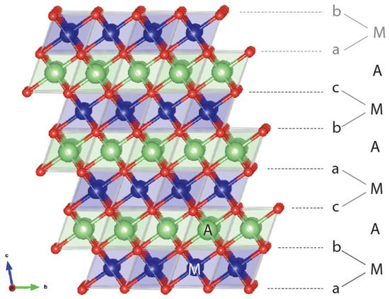
A layered rocksalt cathode oxide adopts the general formula AxMO2 (A: alkali cation, M: metal cation, O: oxygen anion). The O anions form a face-centered cubic (FCC) framework with octahedral and tetrahedral sites. These two environments are face sharing and form a topologically connected network. When fully alkaliated such that x ~ 1, the compound consists of AO2 and MO2 edge-sharing octahedra. The layered structure, illustrated in Figure 1, is aptly named because AO2/MO2 octahedra form alternating (111) planes of the FCC oxygen lattice when fully lithiated. The A and M cations alternate in the abc repeat unit of the oxygen framework to form a−b_c−a_b−c_, stacking where the minus sign “−” indicates the location of M and the underscore “_” gives the position of the A ions. Because the oxygen stacking has a repeat unit of three and the metal layering repeats every two layers, periodicity is achieved after six oxygen layers. Under the structural classification by Delmas et al. for layered cathode oxides [4], the layered rocksalt cathode structure is commonly referred to as O3: O for the octahedral alkali ion environment (not to be confused with O for oxygen) and 3 for the number of MO2 slabs in a repeat unit. The O3 structure is equivalent to the structure of α-NaFeO2 and the cation ordering is also known in metallic alloys as L11 (CuPt prototype) [5].

Figure 1. Representative O3 structure showing the abc stacking sequence of oxygen ions (red), thus creating various coordination environments for the alkali ion A (green) and metal ion M (blue). In an O3 repeat unit, M and A are coordinated below and above by oxygen layers. The beginning of another repeat unit with a-M-b stacking is in gray.
It is now well understood that the ordering of AO2 and MO2 in alternating layers is not the most favored cation ordering from an electrostatic perspective. Instead, the layered structure finds its stability in the size difference of A and M [6][7][6,7] as it allows A-O and M-O bond distances to relax independently of each other. This independent A-O and M-O bond accommodation explains how a larger A cation, such as Na+, can form the layered structure with a wide range of M radii [8], whereas a smaller A, such as Li+, only forms stable O3 compounds with a limited range of smaller M radii, namely Co3+ [9], V3+ [10], Ni3+ [11], and Cr3+ [10].
2. Evolution from LiCoO2 to NMC
Today, O3 cathodes have evolved in several directions from LiCoO2 [12] for use cases beyond portable electronics. Anticipating potential cost and resource problems with Co [13], research in the 1980s and 1990s mostly focused on substitutions of Co by Ni [14]. However, consideration of the low cost of Mn and the high stability of the Mn4+ charge state led the community towards layered LiMnO2. Even though this structure is not the thermodynamically stable state of LiMnO2 [15], Delmas [16] and Bruce [17] were able to synthesize it by ion exchange from the stable NaMnO2. Unfortunately, the high mobility of Mn3+ [18] leads to a rapid transformation of the layered structure into the spinel structure upon cycling [19] because of its pronounced energetic preference at the Li0.5MnO2 composition [20]. Attempts to stabilize layered LiMnO2 with Al [21] or Cr [22][23][22,23] substitution were only partially successful and led to the formation of a phase intermediate between layered and spinel [24]. Then, in 2001, several key papers were published that would pave the way for the highly successful Ni-Mn-Co (NMC) cathode series: Ohzuku showed very high capacity and cyclability in Li(Ni1/3Mn1/3Co1/3)O2 [25], known as NMC-111, and in Li(Ni1/2Mn1/2)O2 [26]; Lu and Dahn published their work on the Li(NixCo1−2xMnx)O2 [27] and its Co-free Li-excess version Li(NixLi1/3−2/xMn2/3−x/3)O2 [28]. In these compounds Ni is valence +2 and Mn is +4 [29], thereby stabilizing the layered material against Mn migration and providing double redox from Ni2+/Ni4+. At this point the NMC cathode series was born. Since then, Ni-rich NMC cathodes have become of great interest to both academia and industry because they deliver a capacity approaching 200 mAh/g and demonstrate high energy density, good rate capability, and moderate cost [30][31][32][30,31,32].
In this short article, we summarize some general and fundamental understanding we have gained in layered oxide cathodes, without delving into issues with very specific compositions. We focus on the roles of the alkali–alkali interaction, electronic structure, and alkali diffusion, and illustrate how these fundamental features conspire to control the electrochemical behavior of O3-structured layered oxides.
3. Alkali–Alkali Interactions, Alkali/Vacancy Ordering, and Voltage Slope
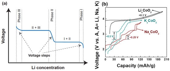
The voltage of a cathode compound is set by the chemical potential of its alkali ions [33] which itself is the derivative of the free energy with respect to alkali concentration. This thermodynamic connection between voltage and free energy creates a direct relation between the voltage profile, the alkali–alkali interactions, and phase transformations as functions of alkali content. While NaxMO2 compounds show many changes in the stacking of the oxygen host layers when the Na content is changed, phase transitions in LixMO2 materials are mostly driven by the Li-vacancy configurational free energy, resulting from Li+-Li+ interactions in the layer [20][34][20,34]. In layered compounds with a single transition metal, such as LixCoO2 and LixNiO2, such phase transitions are easily observed as voltage plateaus and steps in the electrochemical charge–discharge profiles as shown in Figure 2a. For a first-order phase transformation, for example from Phase I to Phase II, the Gibbs phase rule dictates that the Li chemical potential should be constant, hence the voltage remains constant while one phase transforms into the other. Phases in which the alkali ions are well-ordered usually display a rapid voltage change as the alkali content is changed, reflecting the high energy cost of trying to create off-stoichiometry in ordered phases. This is in contrast to solid solutions which have smoother voltage profiles as a function of alkali concentration. For example, both theory [35] and experiments [36][37][36,37] indicate that in LixCoO2 a monoclinic phase appears with lithium and vacancies ordered in rows for x ≈ 0.5 [36]. In LixNiO2, Li-vacancy ordering is responsible for stable phases at x ~ 0.8, ~0.5, and ~0.25–0.3 [38][39][40][38,39,40]. When many transition metals are mixed, as in NMC cathodes, the Li+-Li+ interaction remains present, but Li-vacancy ordering is suppressed by the electrostatic and elastic perturbations on the Li site caused by the distribution of the Ni, Mn and Co in the transition metal layers.

Figure 2. (a) Typical charge–discharge of intercalation-based cathode materials. A voltage step indicates new phase formation. (b) Charge–discharge comparison of O3-LixCoO2, P2-NaxCoO2, and P2-KxCoO2 [41][42][43][44,47,48]. Voltage curves for P2-NaxCoO2, P2-KxCoO2, and O3-LixCoO2 are reproduced with permissions from [41][42][43][44,47,48]. The voltage curve for P2-KxCoO2 is licensed under CC BY-NC 4.0 [42][47].
The Li+-Li+ interaction is mostly electrostatic but is highly screened by the charge density on the oxygen ions, leading to a rather small effective interaction in layered LixMO2 compounds and small voltage slope. This is a critical feature of LixMO2 compounds that gives them high capacity in a relatively narrow voltage window compared to other alkali compounds, as explained below. The effective interaction between intercalating ions increases significantly when larger alkali ions (e.g., Na+ and K+) are used in the layered structure [44][45][46][41,42,43]. These larger alkali ions increase the oxygen slab distance, reducing the oxygen charge density available for screening within the alkali layer [20][45][46][20,42,43]. The larger effective repulsion between the Na+ or K+ ions affects the phase transition and electrochemistry in a very significant way as shown in Figure 2b. For example, NaxCoO2 has stronger Na-vacancy ordering and thus more pronounced voltage steps compared to LixCoO2. This phenomenon [41][47][44,45] becomes even more significant in KxCoO2 [48][42][46,47]. The effect of the intercalant’s size on the phase transitions and voltage steps is not just limited to Co-containing compounds but is also generally applicable to other transition metal systems as described in a recent review [46][43].
