Your browser does not fully support modern features. Please upgrade for a smoother experience.
Please note this is a comparison between Version 2 by Peter Tang and Version 1 by Luka Boban.
Geothermal energy is a widely available, constant source of renewable energy that has shown great potential as an alternative source of energy in achieving global energy sustainability and environment protection. When exploiting geothermal energy, whether is for heating or cooling of buildings, a ground heat exchanger (GHE) is the most important component, whose performance can be easily improved by following the latest design aspects.
- shallow geothermal energy
- ground heat exchanger
- design and configuration
1. Introduction
Geothermal energy is a renewable form of energy that can be used for electricity production or can be utilized for heating and cooling applications [1]. The latter is commonly described as low temperature, shallow geothermal energy use where ground resources up to approximately 400 m below the surface are used. To do so, different types of ground heat exchangers (GHEs) are buried underground to exchange heat with the surrounding soil. Based on installation depth, systems are commonly divided into horizontal systems that are installed just below the surface in excavated trenches and vertical systems where boreholes are drilled to larger depths and grouted. In between, a group of shallow systems up to the depth of 30 m in form of energy piles or large diameter helical coils exist. Geothermal systems can also be classified as open or closed systems [2]. In an open system configuration, air or water from the surrounding flows through a heat exchanger, exchanging heat with the underground, and is then used in heating, cooling, or ventilation systems. In a closed configuration, secondary working fluid circulates in a heat exchanger in the closed-loop and exchanges heat with the underground; therefore, only heat transfer is accounted for.
Ground coupled system efficiency is based on the stable underground temperature that results from the combined effect of the ground thermal inertia that dampens the temperature changes on the surface and continuous geothermal gradient [3]. Depending on the depth, the underground temperature is higher in winter and lower in summer compared to the outside air. Direct use of shallow geothermal energy is possible in the ground-to-earth heat exchangers for partial or complete conditioning of inlet air used for ventilation. The temperature level of the shallow underground usually is not enough to fully cover cooling and heating needs, so ground heat exchangers are coupled to heat pumps (GSHP) [1,4][1][4]. Heat pump performance is strongly dependent on a heat sink and source temperatures; therefore, it is imperative that the ground heat exchanger is designed efficiently and cost-effectively, as installation costs increase with installation depth [5,6][5][6].
2. Different types of Ground Heat Exchangers
2.1. Horizontal Heat Exchanger Configurations
Horizontal configurations include the direct use of ground thermal energy in the air to ground heat exchangers and horizontal ground heat exchangers coupled to the heat pump system. Both types of systems are installed in surface soil layers, where performance is affected by seasonal variations of soil temperature and moisture content. Local geological conditions, mainly ground thermal conductivity and heat capacity, affect the heat transfer in the underground.
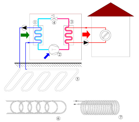
Earth-to-air heat exchangers are the simplest configuration of heat exchangers when the use of renewable underground energy is considered. Commonly, they are abbreviated as EAHE [17[7][8],58], GAHE [59][9], or HAGHE [60[10][11],61], where the additional H letter designates horizontal installation. In an open system configuration, ambient air passes through the pipes inserted in the ground and exchanges heat with the ground [2]. Depending on the season, the air is heated or cooled before being distributed through the ventilation system or used as a heat source for an air source heat pump [62][12] (Figure 1). EAHE can also be employed as part of the thermally activated building systems (TABSs), where walls are constructed as hollow prefabricated building components or pipes are embedded inside walls [63][13]. In such systems, a closed-loop configuration can be used [41][14].


Figure 1. Earth to air heat exchanger used for an air supply in a ventilation system (left) and coupled to the air source heat pump (right) (1—evaporator, 2—compressor, 3—condenser, 4—expansion valve, 5—earth to air heat exchanger).
Horizontal ground heat exchangers (HGHE) are used as a closed system and are coupled to the heat pump. The ground exchanges thermal energy with the working fluid inside pipes. Being installed in 1–2 m deep trenches, their performance is comparatively lower than the vertical GSHP systems. The needed installation area for the horizontal system is larger, but installation costs are smaller compared to the vertical heat exchangers [2]. Based on pipe loop geometry, horizontal systems can be divided into linear-loop, spiral-coil, and slinky-coil configurations [11[15][16],48], and based on loop connections system can be further divided into a trench, series, and parallel configurations [48][16] (Figure 2). Compared to linear configurations, coil configurations enable more efficient use of the available ground while requiring longer pipes and increased pump work [64][17].


Figure 2. Horizontal heat exchanger coupled to the heat pump (1—evaporator, 2—compressor, 3—condenser, 4—expansion valve, 5—linear loop, 6—slinky coil, 7—spiral coil).
2.2. Vertical Heat Exchanger Configurations
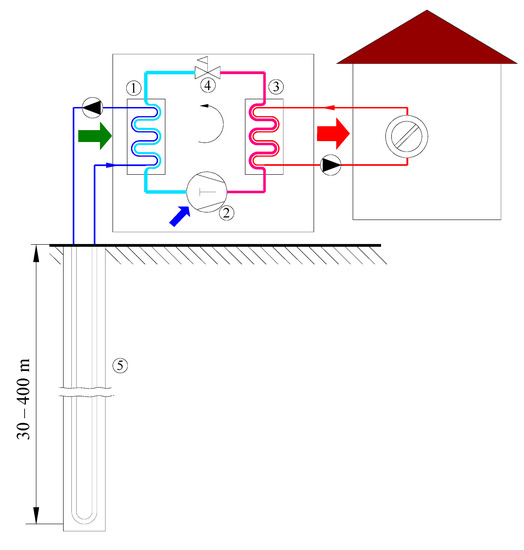
When sufficient ground area is available, as mentioned, horizontal GHEs present the most cost-effective option. However, if the available area is limited, the ground surface is rocky, and visual interference with the landscape is not welcome, vertical GHEs are applied. Vertical ground heat exchangers (VGHE) are also referred to as borehole heat exchangers (BHEs). In comparison with horizontal GHEs, BHEs have higher installation costs and more stable performance, as they are not affected severely by ambient air [65][18]. Vertical GHEs are divided into two groups depending on the depth of the borehole and, consequently, the type of heat exchanger. The first group, shallow boreholes GHE (<400 m), are usually used in combination with heat pumps (ground-coupled heat pumps—GCHP) as a source or sink for thermal energy (Figure 3). A traditional configuration consists of the borehole with a diameter usually around 100–200 mm containing U-tubes with a diameter in the range of 19–38 mm for working fluid to circulate [65][18]. Besides the most common single U-tube configuration, other configurations that can be used are double or triple U-tube, W-shaped tube, coaxial tube, and helical-shaped tube [53][19]. The annulus section of the borehole is made from various backfill materials referred to as grout, which reduces the thermal resistance between the pipes and ground and ensures good contact between materials. As the heat transfer area of such systems is limited, consequently, the thermal capacity (thermal power) of such systems is also limited. To achieve a higher thermal capacity of such systems, there are two possible solutions—increasing the number of boreholes (most of today’s installations) or increasing the depth of the borehole [66][20]. Increasing the number of boreholes is only available when there is sufficient available space.


Figure 3. Vertical borehole heat exchanger coupled to the heat pump (1–evaporator, 2—compressor, 3—condenser, 4—expansion valve, 5—borehole heat exchanger).
The second option, to increase the thermal capacity of GHE, uses the technology of the deep borehole heat exchangers (DBHE), which can be also classified as the second category of vertical BHE. DBHE can extract medium-deep geothermal energy at high temperatures [67][21]. Although the literature does not give, to our knowledge, strict classification of BHEs by depth, a good definition is proposed by Sapinska-Sliwa et al. [67][21]. They proposed that deep borehole heat exchangers (DBHE) are those where there is a possibility that the extracted heat can be used directly (without the aid of HP). When using the technology of DBHE, classical U-tubes configurations are usually replaced with coaxial (pipe in a pipe) borehole heat exchangers, which have a larger heat transfer area and can sustain a larger flow rate (lower pumping costs) [68][22]. As over 50% of the total cost of the geothermal project can be drilling costs [69][23], a good solution to reduce high drilling costs is presented by using depleted and abandoned gas and oil wells, which has been extensively investigated recently [70,71,72,73][24][25][26][27]. Depending on the obtained temperature in DBHE, these systems can be used for direct space heating [74[28][29],75], coupled with heat pumps [76[30][31][32],77,78], or even in power production systems [79][33].
2.3. Shallow Ground Heat Exchanger Configurations
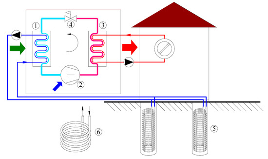
Most prevailing GHE configurations include horizontal and vertical design, the former having low installation costs and the latter having superior thermal performance due to ground temperature stability. In between, shallow systems incorporate advantages of both systems: less expensive excavation works and use of ground layers where the effect of surface conditions are damped [80][34]. The application of this GHE layout is interesting in urban environments with increased ground temperature and limited installation area or in locations where deep drilling is prohibited to prevent disturbance of aquifers [81][35]. Shallow systems include a large diameter, to increase the heat transfer area, conically or helically shaped configurations [82[36][37][38],83,84], or pipes embedded in building piles (energy piles) [85][39] (Figure 4). An alternative configuration of a coil GHE inserted in a water tank with PCM and used as an underground thermal battery was proposed by Warner et al. [86][40]. The authors concluded that the performance of this layout is comparable with vertical BHE with the same heat transfer surface area.


Figure 4. Shallow heat exchanger coupled to the heat pump (1—evaporator, 2—compressor, 3—condenser, 4—expansion valve, 5—energy piles, 6—large diameter coil GHE).
2.4. Direct Expansion Systems
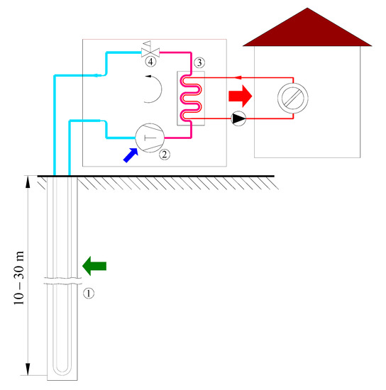
R&D in the field of ground physics allowed us to determine accurate soil temperature profiles and thermal properties. Modeling these properties in cooperation with advanced control systems and overcoming some of the design challenges was a prerequisite for use of direct expansion (DX) systems [87][41]. Compared to previously mentioned heat exchangers with water or glycol mixtures often used as indirect heat pump secondary circuit, DX systems act as evaporators or condensers of a heat pump whose working fluid is heat pump refrigerant (Figure 5). This setup removes the need for a heat exchanger between the fluid circles as well as a circulation pump. A ground heat exchanger design with the DX of refrigerant needs to follow some specific rules concerning the type of refrigerant, refrigerant charging, oil return to the compressor, depth of the vertical borehole heat exchanger, and possible ground pollution due to refrigerant leak [88][42]. The ground heat exchanger can be placed horizontally, vertically, or in a slinky manner. Exchangers with vertical configuration are predominant [36][43]. Several researchers have investigated dynamic heat transfer analysis of the two-phase flow in the ground evaporator and the heat exchange with ground [89,90,91,92][44][45][46][47]. De Carli et al. [89][44] developed the mathematical models of evaporation in the vertical U-tube. Li et al. [91][46] developed and validated numerically and experimentally a three-dimensional transient thermal resistance and capacity model of a novel direct expansion downhole heat exchanger. Additionally, Nguyen et al. [92][47] evaluated a pressure-enthalpy coupled thermal resistance and capacity model for a direct expansion vertical borehole heat exchanger for supercritical CO2 application.


Figure 5. Direct expansion borehole heat exchanger (1—evaporator/BHE, 2—compressor, 3—condenser, 4—expansion valve).
References
- Soltani, M.; Kashkooli, F.M.; Dehghani-Sanij, A.R.; Kazemi, A.R.; Bordbar, N.; Farshchi, M.J.; Elmi, M.; Gharali, K.; B. Dusseault, M. A comprehensive study of geothermal heating and cooling systems. Sustain. Cities Soc. 2019, 44, 793–818.
- Florides, G.; Kalogirou, S. Ground heat exchangers-A review of systems, models and applications. Renew. Energy 2007, 32, 2461–2478.
- Carotenuto, A.; Ciccolella, M.; Massarotti, N.; Mauro, A. Models for thermo-fluid dynamic phenomena in low enthalpy geothermal energy systems: A review. Renew. Sustain. Energy Rev. 2016, 60, 330–355.
- Lucia, U.; Simonetti, M.; Chiesa, G.; Grisolia, G. Ground-source pump system for heating and cooling: Review and thermodynamic approach. Renew. Sustain. Energy Rev. 2017, 70, 867–874.
- Atam, E.; Helsen, L. Ground-coupled heat pumps: Part 1—Literature review and research challenges in modeling and optimal control. Renew. Sustain. Energy Rev. 2016, 54, 1653–1667.
- Atam, E.; Helsen, L. Ground-coupled heat pumps: Part 2—Literature review and research challenges in optimal design. Renew. Sustain. Energy Rev. 2016, 54, 1668–1684.
- Rouag, A.; Benchabane, A.; Mehdid, C.E. Thermal design of Earth-to-Air Heat Exchanger. Part I a new transient semi-analytical model for determining soil temperature. J. Clean. Prod. 2018, 182, 538–544.
- Yusof, T.M.; Ibrahim, H.; Azmi, W.H.; Rejab, M.R.M. Thermal analysis of earth-to-air heat exchanger using laboratory simulator. Appl. Therm. Eng. 2018, 134, 130–140.
- Agrawal, K.K.; Misra, R.; Agrawal, G. Das to study the effect of different parameters on the thermal performance of ground-air heat exchanger system: In situ measurement. Renew. Energy 2020, 146, 2070–2083.
- Congedo, P.M.; Lorusso, C.; Baglivo, C.; Milanese, M.; Raimondo, L. Experimental validation of horizontal air-ground heat exchangers (HAGHE) for ventilation systems. Geothermics 2019, 80, 78–85.
- Baglivo, C.; D’Agostino, D.; Congedo, P.M. Design of a ventilation system coupled with a horizontal air-ground heat exchanger (HAGHE) for a residential building in a warm climate. Energies 2018, 11, 2122.
- Baglivo, C.; Bonuso, S.; Congedo, P.M. Performance Analysis of Air Cooled Heat Pump Coupled with Horizontal Air Ground Heat Exchanger in the Mediterranean Climate. Energies 2018, 11, 2704.
- Xu, X.; Yu, J.; Wang, S.; Wang, J. Research and application of active hollow core slabs in building systems for utilizing low energy sources. Appl. Energy 2014, 116, 424–435.
- Gao, J.; Li, A.; Xu, X.; Gang, W.; Yan, T. Ground heat exchangers: Applications, technology integration and potentials for zero energy buildings. Renew. Energy 2018, 128, 337–349.
- Habibi, M.; Hakkaki-Fard, A. Evaluation and improvement of the thermal performance of different types of horizontal ground heat exchangers based on techno-economic analysis. Energy Convers. Manag. 2018, 171, 1177–1192.
- Cui, Y.; Zhu, J.; Twaha, S.; Chu, J.; Bai, H.; Huang, K.; Chen, X.; Zoras, S.; Soleimani, Z. Techno-economic assessment of the horizontal geothermal heat pump systems: A comprehensive review. Energy Convers. Manag. 2019, 191, 208–236.
- Kim, M.J.; Lee, S.R.; Yoon, S.; Go, G.H. Thermal performance evaluation and parametric study of a horizontal ground heat exchanger. Geothermics 2016, 60, 134–143.
- Yang, H.; Cui, P.; Fang, Z. Vertical-borehole ground-coupled heat pumps: A review of models and systems. Appl. Energy 2010, 87, 16–27.
- Cui, Y.; Zhu, J.; Twaha, S.; Riffat, S. A comprehensive review on 2D and 3D models of vertical ground heat exchangers. Renew. Sustain. Energy Rev. 2018, 94, 84–114.
- Holmberg, H.; Acuña, J.; Næss, E.; Sønju, O.K. Thermal evaluation of coaxial deep borehole heat exchangers. Renew. Energy 2016, 97, 65–76.
- Sapinska-Sliwa, A.; Rosen, M.A.; Gonet, A.; Sliwa, T. Deep Borehole Heat Exchangers-A Conceptual and Comparative Review. Int. J. Air-Cond. Refrig. 2016, 24.
- Beier, R.A. Thermal response tests on deep borehole heat exchangers with geothermal gradient. Appl. Therm. Eng. 2020, 178, 115447.
- Bu, X.; Ma, W.; Li, H. Geothermal energy production utilizing abandoned oil and gas wells. Renew. Energy 2012, 41, 80–85.
- Lo Russo, S.; Gizzi, M.; Taddia, G. Abandoned oil and gas wells exploitation by means of closed-loop geothermal systems: A review. Geoing. Ambient. Min. 2020, 160, 3–11.
- Macenić, M.; Kurevija, T. Revitalization of abandoned oil and gas wells for a geothermal heat exploitation by means of closed circulation: Case study of the deep dry well Pčelić-1. Interpretation 2018, 6, SB1–SB9.
- Mehmood, A.; Yao, J.; Fan, D.; Bongole, K.; Liu, J.; Zhang, X. Potential for heat production by retrofitting abandoned gas wells into geothermal wells. PLoS ONE 2019, 14, e0220128.
- Nian, Y.-L.; Cheng, W.L.; Yang, X.Y.; Xie, K. Simulation of a novel deep ground source heat pump system using abandoned oil wells with coaxial BHE. Int. J. Heat Mass Transf. 2019, 137, 400–412.
- Dai, C.; Li, J.; Shi, Y.; Zeng, L.; Lei, H. An experiment on heat extraction from a deep geothermal well using a downhole coaxial open loop design. Appl. Energy 2019, 252, 113447.
- Li, C.; Guan, Y.; Liu, J.; Jiang, C.; Yang, R.; Hou, X. Heat transfer performance of a deep ground heat exchanger for building heating in long-term service. Renew. Energy 2020, 166, 20–34.
- Luo, Y.; Xu, G.; Yan, T. Performance evaluation and optimization design of deep ground source heat pump with non-uniform internal insulation based on analytical solutions. Energy Build. 2020, 229, 110495.
- Deng, J.; Wei, Q.; He, S.; Liang, M.; Zhang, H. Simulation analysis on the heat performance of deep borehole heat exchangers in medium-depth geothermal heat pump systems. Energies 2020, 13, 754.
- Yao, J.; Liu, W.; Zhang, L.; Tian, B.; Dai, Y.; Huang, M. Performance analysis of a residential heating system using borehole heat exchanger coupled with solar assisted PV/T heat pump. Renew. Energy 2020, 160, 160–175.
- Alimonti, C.; Soldo, E. Study of geothermal power generation from a very deep oil well with a wellbore heat exchanger. Renew. Energy 2016, 86, 292–301.
- Najib, A.; Zarrella, A.; Narayanan, V.; Grant, P.; Harrington, C. A revised capacitance resistance model for large diameter shallow bore ground heat exchanger. Appl. Therm. Eng. 2019, 162, 114305.
- Rivera, J.A.; Blum, P.; Bayer, P. Increased ground temperatures in urban areas: Estimation of the technical geothermal potential. Renew. Energy 2017, 103, 388–400.
- Agbossou, A.; Souyri, B.; Stutz, B. Modelling of helical coil heat exchangers for heat pump applications: Analysis of operating modes and distance between heat exchangers. Appl. Therm. Eng. 2018, 129, 1068–1078.
- Boughanmi, H.; Lazaar, M.; Bouadila, S.; Farhat, A. Thermal performance of a conic basket heat exchanger coupled to a geothermal heat pump for greenhouse cooling under Tunisian climate. Energy Build. 2015, 104, 87–96.
- Najib, A.; Zarrella, A.; Narayanan, V.; Bourne, R.; Harrington, C. Techno-economic parametric analysis of large diameter shallow ground heat exchanger in California climates. Energy Build. 2020, 228, 110444.
- Cui, Y.; Zhu, J. Year-round performance assessment of a ground source heat pump with multiple energy piles. Energy Build. 2018, 158, 509–524.
- Warner, J.; Liu, X.; Shi, L.; Qu, M.; Zhang, M. A novel shallow bore ground heat exchanger for ground source heat pump applications—Model development and validation. Appl. Therm. Eng. 2020, 164, 114460.
- Badache, M.; Eslami-Nejad, P.; Bastani, A.; Aidoun, Z.; Nguyen, A. Theoretical and experimental analysis of a vertical direct expansion geothermal evaporator using CO2 as refrigerant. Sci. Technol. Built Environ. 2019, 25, 1081–1094.
- Ndiaye, D. Reliability and performance of direct-expansion ground-coupled heat pump systems: Issues and possible solutions. Renew. Sustain. Energy Rev. 2016, 66, 802–814.
- Bastani, A.; Eslami-Nejad, P.; Badache, M.; Nguyen, A.T.A. Experimental characterization of a transcritical CO2 direct expansion ground source heat pump for heating applications. Energy Build. 2020, 212.
- De Carli, M.; Fiorenzato, S.; Zarrella, A. Performance of heat pumps with direct expansion in vertical ground heat exchangers in heating mode. Energy Convers. Manag. 2015, 95, 120–130.
- Gao, Y.; Gao, T.; Liu, Z. Study on the heat transfer performance of boiling in vertical buried tube of direct expansion ground source heat pump. Energy Procedia 2019, 158, 5494–5503.
- Li, Y.; Xu, W.; Ma, L.; Zhao, J.; Li, W.; Wang, S.; Liu, J. Dynamic heat transfer analysis of a direct-expansion CO2 downhole heat exchanger. Appl. Therm. Eng. 2021, 189, 116733.
- Nguyen, A.; Elsami-Nejad, P.; Badache, M.; Bastani, A. Pressure–enthalpy coupled thermal resistance and capacity model (PH-TRCM) for direct-expansion borehole heat exchangers: Application for supercritical CO2. Geothermics 2018, 76, 50–59.
More
