Advanced martensitic steels (AMSs) developed for sheet and wire rod products have a tensile strength higher than 1.5 GPa, good cold-formability, superior toughness and fatigue strength, and delayed fracture strength due to a mixture of martensite and retained austenite, compared with the conventional martensitic steels.
- advanced martensitic steel
- retained austenite characteristics
- microstructure
- mechanical properties
- heat treatment
- hot-stamping
- hot-forging
- case hardening
1. Introduction
The strain-induced transformation of austenite to martensite enhances the ductility of austenitic steels such as Fe-Ni, Fe-Ni-C, and Fe-Cr-Ni steels. These high-alloy austenitic steels are called TRansformation-Induced Plasticity (TRIP) steels [1][2][1,2]. In the 1980s, low and medium carbon Si-Mn ferritic steels subjected to intercritical annealing and then isothermal transformation (IT) or austempering process were developed by Sakuma et al. [3][4][3,4]. The steel is named low alloy TRIP-aided steel or TRIP-assisted steel because it achieves high ductility by the TRIP effect of metastable retained austenite of 5 to 30 vol %. The TRIP-aided steel was mainly applied to the automotive body parts that need high cold press formability and weldability [4][5][6][4,5,6]. The product of tensile strength and total elongation (TS×TEl) of various AHSSs as a function of austenite or retained austenite fraction is shown in Figure 1. Hereafter, these third-generation AHSSs (type B) are also called low and medium-carbon “Advanced Martensitic Steel (AMS)”, because the martensitic structure is the main matrix structure.
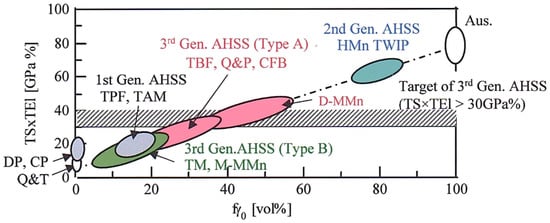
Figure 1. Relationship between the product of tensile strength and total elongation (TS×TEl) and initial volume fraction of austenite or retained austenite (fγ0) in the first-, second-, and third-generation (Type A and Type B) advanced high-strength steels (AHSSs). Q&T: conventional quenched and tempered martensitic steel, DP: ferrite–martensite dual-phase steel, CP: complex-phase steel, TPF, TAM, TBF, and TM: transformation-induced plasticity (TRIP)-aided steels with polygonal ferrite, annealed martensite, bainitic ferrite, and martensite matrix structure, respectively. Q&P: one-step and two-step quenched and partitioned steel, CFB: carbide-free bainitic steel, D-MMn: duplex-type medium Mn steel, M-MMn: martensite-type medium Mn steel, HMn TWIP: high manganese TWIP steel, Aus: austenitic steel. This figure is reproduced based on Ref. [7][52]. Reprinted with permission from Elsevier: Mater. Sci. Eng. A, Copyright 2021.
2. Two Kinds of Heat-Treatment Process for AMSs
The heat-treatment process of AMS is as simple as the Q&T process of the conventional martensitic steels. In addition, the process after austenitizing is conducted at relatively low temperature, compared with those of TBF, Q&P, and CFB steels [8][9][10][11][12][13][14][15][16][17][18][19][20][21][58,59,60,61,62,63,66,67,68,69,70,71,72,73].
When the Mf of the AMS is higher than room temperature, the IT process below Mf [9][10][11][12][13][59,60,61,62,63] or DQ process [22][8][9][10][11][12][13][18][19][20][21][53,58,59,60,61,62,63,70,71,72,73] immediately after austenitizing and hot-rolling is conducted using an oil bath below 200 °C (Figure 2a). In the case of the DQ process, partitioning is added after the DQ process (named DQ-P process) [9][10][18][19][20][59,60,70,71,72]. The partitioning temperatures just below and above Mf are recommended to minimize the increase in carbide precipitation and the decrease in retained austenite fraction [9][10][59,60]. Unlike this, Gao et al. propose the partitioning (tempering) temperature above Ms [18][19][20][70,71,72]. Such IT and DQ-P processes (Figure 2a) are applied to Si/Al-Mn steels with low and medium carbon content [9][10][11][12][13][59,60,61,62,63] and with a medium manganese content of about 5% [23][14][65,66]. Regarding M-MMn steels, air cooling to room temperature is possible instead of quenching in oil or water bath due to the high hardenability [24][25][26][27][28][64,77,78,79,80]. On the other hand, when the Mf of the AMS is lower than room temperature such as for M-MMn steel with a relatively high Mn content of about 10 mass %, the DQ or DQ-P process is carried out [15][16][17][67,68,69] (Figure 2b).
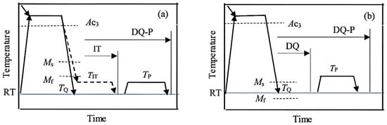
Figure 2. Heat treatment diagrams of (a) the isothermal transformation (IT) process below Mf and direct quenching to room temperature (RT) followed by partitioning (DQ-P) process in a case of RT < Mf [8][9][10][11][12][13][58,59,60,61,62,63] and (b) the DQ and DQ-P process in a case of RT > Mf [15][16][17][67,68,69]. RT: room temperature, TIT: isothermal transformation temperature, TQ: quenching temperature, TP: partitioning temperature.
3. Microstructure and Retained Austenite Characteristics of AMSs
3.1. IT and DQ-P Processes (RT < M
f
)
When 0.21%C–1.49%Si–1.50%Mn–1.0%Cr–0.05%Mn TM steel is subjected to the IT process at temperatures below Mf (261 °C) and the DQ process, most of the austenite start to transform to soft coarse lath-martensite accompanied with auto-tempering [9][10][11][12][13][59,60,61,62,63] (Figure 3 and Figure 4a). The other austenites are retained as filmy and blocky morphology in the lath-martensite structure matrix, and a part of retained austenite stays in the fine MA phase [29][9][10][11][12][13][35,59,60,61,62,63].
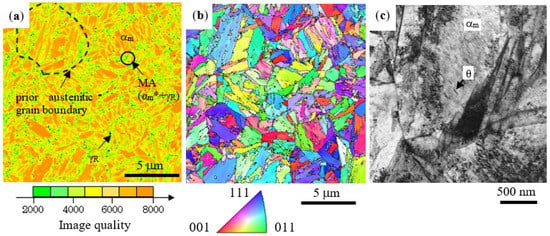
Figure 3. (a) Image quality distribution map and (b) inverse pole figure map of Fe-α (body centered cubic structure) phase and (c) TEM image in 0.21%C–1.49%Si–1.50%Mn–1.0%Cr–0.05%Mn TM steel subjected to the IT process at Tp = 200 °C (< Mf) for 1000 s [12][62]. αm: coarse lath-martensite, αm*: fine lath/twin-martensite, γR: retained austenite (black dots), MA: martensite/austenite phase, θ: carbide in coarse lath-martensite. Reprinted with permission from ISIJ: ISIJ Int, Copyright 2021.
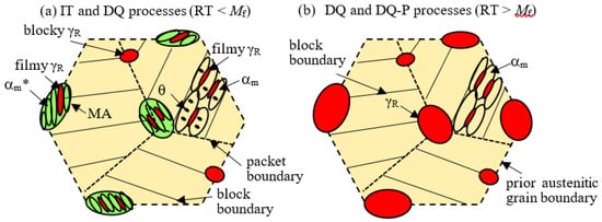
Figure 4. Illustration of typical microstructures of advanced martensitic steels (AMSs) subjected to (a) the IT and DQ processes in the case of RT < Mf and (b) the DQ and DQ-P processes in the case of RT > Mf. RT: room temperature. αm, αm*, γR, θ and MA represent coarse lath-martensite, fine lath/twin-martensite, retained austenite, carbide and MA phase, respectively.
According to Sugimoto et al. [10][11][13][60,61,63], the retained austenite fraction increases with increasing IT temperature, with a constant carbon concentration, in an IT temperature range of 25 to 250 °C in 0.21%C–1.49%Si–1.50%Mn–1.0%Cr–0.05%Nb TM steel (Figure 5a), where the IT process at 25 °C is corresponding to the DQ process. It is noteworthy that the MA phase fraction increases and the carbide fraction decreases with increasing IT temperature in the TM steel (Figure 5b). The carbide fraction is 1/4 to 1/2 times that of JIS-SCM420 Q&T steel. Additions of Cr and Mo hardly influence the retained austenite fraction (about 4 vol %) but increase the MA phase fraction and decrease the carbide fraction [9][12][59,62]. An increase in Mn content significantly increases the volume fraction of retained austenite in 0.2%C–1.5%Si–1.5%Mn TM steel [23][14][65,66]. The mechanical stability of the retained austenite defined by the following strain-induced transformation factor k [6] is nearly constant in an IT temperature range below Mf in the same way as the carbon concentration of the retained austenite (Figure 5b,c).
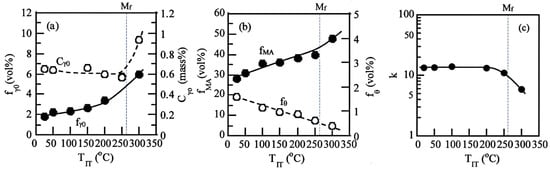
Figure 5. Variations in (a) initial volume fraction (fγ0) and initial carbon concentration (Cγ0) of retained austenite, (b) volume fractions of MA phase (fMA) and carbide (fθ), and (c) strain-induced transformation factor (k) as a function of IT temperature (TIT) in 0.21%C–1.49%Si–1.50%Mn–1.0%Cr–0.05%Nb TM steel [11][61]. The IT process at 25 °C is corresponding to the DQ process. Reprinted with permission from AIST: AIST 2013, Copyright 2021.
3.2. DQ and DQ-P Processes (RT > M
f
)
The DQ process at the temperatures above Mf produces a simple duplex structure of soft coarse lath-martensite structure matrix and blocky and filmy retained austenite in 0.2%C–10%Mn–2%Al–0.1%V [15][16] (Figure 4b). The soft lath-martensite fraction (fαm) can be estimated by the following empirical equation proposed by Koistinen and Marburger [30][31].
3.3. Ausforming
where TQ is the quenching temperature. It is noteworthy that the retained austenite fraction is much higher than that of TM steel subjected to the IT process of Figure 2a [15][16]. Differing from the IT process (Figure 4a), the MA phase and carbide are hardly formed because the process is not cooled to temperatures below Mf, similar to TBF, Q&P, and CFB steels with a BF/M matrix structure [32][33][34][35][36][37][38][39][40]. In addition, such a microstructure without carbide in the sosft lath-martensite resembles that of 0.23%C–2.3%Mn–1.5%Si–12.5%Cr–0.03%Ti–0.05%Nb martensitic stainless steel containing retained austeniterming at [41].
3.3. Ausforming
Ausforming at temperatures between Ac3 and Ms before the IT, DQ, and DQ-P process can not only reduce the Ms due to the strengthening of austenite but also introduce deformation defects and elongate the microstructure [42][81], in the same way as TBF [43][84] and CFB [44][49] steels. If the ausforming is conducted under the conditions of relatively high temperature and large plastic strain, prior austenitic grain is refined, although dislocation density is decreased.
4. Tensile Properties and Cold Formability of AMS Sheets
4.1. Tensile Properties
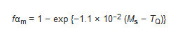
The IT process brings on the continuous yielding and low yield stress (or 0.2% offset proof stress) at room temperature in 0.21%C–1.49%Si–1.50%Mn–1.0%Cr–0.05%Nb TM steel (Figure 6). The main origin is due to a large amount of hard MA phase [11][12][13][61,62,63], which creates a preferential yielding zone in a matrix as fresh martensite second phase in dual-phase steel, as well as the strain-induced transformation of retained austenite [11][12][13][45][61,62,63,88].
Figure 6. Typical engineering stress−strain (σ−ε) curves at room temperature in 0.21%C–1.49%Si–1.50%Mn–1.0%Cr–0.05%Nb TM steel subjected to the DQ process and the IT process at Tp = 200 °C and 300 °C [13][63]. (a): initial stage, (b) overall stage [13][63]. Measured Ms and Mf of the steel are 406 °C and 261 °C, respectively.
4.2. Formabilities
The best combination of tensile strength and formabilities such as stretch-formability, stretch-flangeability, and bendability can be achieved by the IT process at TIT = 200 °C in 0.21%C–1.49%Si–1.50%Mn–1.0%Cr–0.05%Nb TM steel (Figure 7) [11][61]. This optimum IT temperature (200 °C) is equivalent to Mf—60 °C in the TM steel. All formabilities of the TM steel are superior to those of 22MnB5 Q&T steel and 0.082%C–0.88%Si–2.0%Mn DP steel. The increased stretch-formability may be caused by the TRIP effect of metastable retained austenite. Meanwhile, the high stretch-flangeability is brought from a small degree of damage to the punched hole-surface with a long shear section and a small number of tiny cracks or voids, resulting from the plastic relaxation by the strain-induced transformation of retained austenite. Such small punching damage leads to difficult crack propagation and void growth on hole-expanding [10][11][60,61]. Good bendability is considered to be caused by a high localized ductility. Partitioning after the DQ process further increases these formabilities, but the formabilities are lower than those of the IT process at 200 °C [10][60].
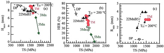
Figure 7. Relationships between (a) maximum stretch height (Hmax), (b) hole expansion ratio (HER) and (c) minimum bending radius (Rmin), and tensile strength (TS) in 0.21%C–1.49%Si–1.50%Mn–1.0%Cr–0.05%Nb TM steel subjected to the DQ process or the IT process at TIT = 100 to 250 °C for 1000 s (●). DP (▽): 0.082%C–0.88%Si–2.0%Mn ferrite–martensite dual-phase steel, DIN-22MnB5 (▲): 0.23%C–0.19%Si–1.29%Mn–0.21%Cr–0.003%B Q&T steel [11][61], 3Mn (◇): 0.2%C–1.5%Si–3%Mn M-MMn steel subjected to the DQ process and the IT process at TIT = 200 °C, 5Mn (◆): 0.2%C–1.5%Si–5%Mn M-MMn steel subjected to the DQ process and the IT process at 100 °C [14][66]. This figure was reproduced from Refs. [11][14][61,66]. Ref. [11][61] is reprinted with permission from AIST: AIST 2013, Copyright 2021.
5. Mechanical Properties of Heat-Treated AMS Plates and Bars
5.1. Impact Toughness and Fracture Toughness
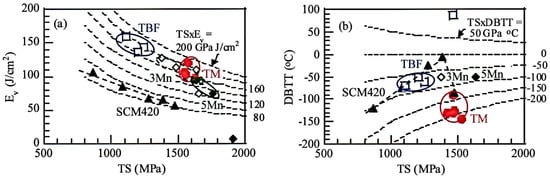
Figure 8. (a) Relationships between (a) Charpy V-notch impact value (Ev) at 25 °C and (b) ductile–brittle fracture transition temperature (DBTT) and tensile strength (TS) in 0.2%C–1.5%Si–1.5%Mn–(0–1.0)%Cr–(0–0.2)%Mn TBF (TIT = 400 °C, □) and TM (DQ-P, Tp = 300 °C, ●) steels, JIS-SCM420 Q&T steel (TT = 200 °C to 600 °C, ▲) and 0.2%C–1.5%Si–3%Mn (◇) and 0.2%C–1.5%Si–5%Mn (◆) M-MMn steels. This figure was reproduced from refs. [23][46][65,74]. Ref. [46][74] was reprinted with permission from Springer Nature: Metall. Mater. Trans. A, Copyright 2021.
5.2. Fatigue Property
0.2%C–1.5%Si–1.5%Mn–1.0%Cr–0.2%Mo TM steel subjected to the DQ-P (Tp = 200 °C) process exhibits large fatigue hardening despite a tensile strength over 1.5 GPa [47][95] (Figure 911a), in the same way as TBF [48][96], CFB [49][97], and high alloy TRIP (16%Cr–7%Mn–8%Ni and 16%Cr–6%Mn–6%Ni) [50][98] steels. Conversely, conventional martensitic steel such as JIS-SCM420 Q&T steel exhibits fatigue softening.
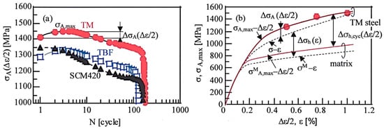
Figure 911. (a) Variations in stress amplitude (σA(∆ε/2)) as a function of the number of cycles (N) under total strain amplitude of ∆ε = 1.5% for 0.2%C–1.5%Si–1.5%Mn–1.0%Cr–0.2%Mo TM subjected to the IT process at TIT = 200 °C and TBF steel (TIT = 350 °C), and JIS-SCM420 Q&T steel (TT = 200 °C). (b) Monotonic stress–strain (σ-ε: dotted lines) and maximum cyclic stress amplitude–strain amplitude (σA,max-∆ε/2: solid red lines) curves for TM steel, as well as the definition of ∆σh(∆ε/2), ∆σh,cyc(∆ε/2), and ∆σA(∆ε/2), in which σM-ε and σMA,max-∆ε/2 are the monotonic and cyclic curves of the assumed matrix structure in the TM steel, respectively [47][95]. Reprinted with permission from Springer Nature: Metall. Mater. Trans. A, Copyright 2021.
5.3. Delayed Fracture Strength
It is well-known that metastable retained austenite can absorb a large amount of solute hydrogen in TBF, Q&P, CFB, and D-MMn steels [51][52][53][54][55][56][57,106,107,108,109,110]. This results in a high delayed fracture strength in these steels because hydrogen concentration on the prior austenitic grain boundary is lowered. In 0.2%C–1.5%Si–1.5%Mn–(0–1.0)%Cr–(0–0.2)%Mo–(0–1.5%%Ni–0.05%Nb TM steels, the DQ-P process (Tp = 250 and 350 °C) increases the delayed fracture strength (maximum fracture strength enduring for 5 h measured by four-point bending tests).
5.4. Wear Property and Overall Performance of Mechanical Properties
When various mechanical properties without wear property of 0.2%C–1.5%Si–1.5Mn TM steel are compared to those of TBF steel with the same composition and DIN-22MnB5 Q&T steel, the TM steel is superior to that of Q&T steel (Figure 105) [57][58][116,117]. The mechanical properties of M-MMn steel are not ready yet. Ausforming at temperatures between Ac3 and Ms is expected to enhance the whole mechanical properties. However, only the effects of ausforming conditions on the tensile strength, total elongation, and impact toughness are reported up to now [59][60][118,119].
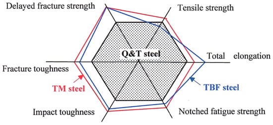
Figure 105. Comparison of various mechanical properties of 0.2%C–1.5%Si–1.5Mn TBF and TM steels and DIN-22MnB5 Q&T steel. This figure was modified based on Ref. [58][117].
6. Case Hardening of AMSs
Fine particle peening (FPP) treatment after the heat-treatment (the DQ-P process, Tp = 180 °C) increases the rotating bending fatigue limits of smooth and notched specimens in 0.20%C–1.50%Si–1.51%Mn–1.0%Cr–0.05%Nb TM steel (Figure 119a) [61][147]. Vacuum carburization (VC) treatment followed by the DQ-P process and subsequent FPP treatment (VC+FPP, Tp = 180 °C) further increases the fatigue limits in 0.2%C–1.5%Si–1.5%Mn–1.0%Cr–0.05%Nb TM steel [62][148]. According to Sugimoto et al., the high fatigue limits are obtained under the conditions of carbon potential of 0.8 mass% (Figure 119b) [62][148] and arc-height of 0.21 mm with a gage N (Figure 119a) [61][147].
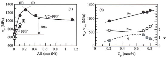
Figure 119. (a) Arc-height (AH) dependence of smooth fatigue limit (σw) in 0.2%C–1.5%Si–1.5%Mn–1.0%Cr–0.05%Nb TM steel (●○) and JIS-SNCM420 Q&T steel (△▲) subjected to fine particle peening (FPP) treatment after heat-treatment (the DQ-P process, Tp = 180 °C) and vacuum carburization (VC) followed by the DQ-P process (Tp = 180 °C) and then fine particle peening (FPP) treatment (VC+FPP) [61][147]. (b) Carbon potential (Cp) dependence of σw, notch-fatigue limit (σwn) and notch sensitivity (q) in the TM steel subjected to VC+FPP treatment [62][148]. (i) Increases in hardness and compressive residual stress, (ii) fish-eye crack fracture at a high depth. Refs. [61][62][147,148] are reprinted with permissions from Springer Nature: Metall. Mater. Trans. A, Copyright 2021 and from Taylor & Francis: Mater. Sci. Technol., Copyright 2021, respectively.