Robotics grippers are one of the most important components in the industry because of their capability to manipulate objects. They not only realize transportation tasks but also perform quality control to optimize robotic work cells. Thanks to the advance in soft material and soft actuators, soft grippers have gained relief in the field of soft robotics in the last years. Soft grippers have considerable flexibility that allows them to grasp a variety of objects, in contrast to hard grippers, which are designed for a specific item. Using the principles of soft robotics, gripping tools with a greater robustness can be developed. This implies that they do not require changes in their programming or construction to manipulate different objects, and the precision needed to make the grips is reduced.
- grasping and manipulation of soft objects
- soft robotics
- soft gripper
1. Background
Although the development of soft robotics is relatively recent, a variety of soft grippers exist, as seen in [1]. Rigid gripping tools with electromechanical actuation are the first step toward soft robotics. Using a chain of rigid elements, grippers can adapt to the shape of the objects. The greater the number of elements that compose the chain, the better the finger profile approximate to that of a continuous line. This is interesting because a larger contact area between the gripping tool and the object leads to a reduced pressure exerted on that area, thus resulting in a lower risk of damaging delicate objects. A prototype based on this idea was developed in 1978. This gripper could adapt to objects of almost any shape and size and grip them with uniform pressure along with the whole finger. Moreover, it presented a relatively simple mechanism and control implemented only with the traction of a pair of wires [2].
An evolution of the previous example is a tendon-driver gripper fabricated through shape deposition manufacturing, which presents joints formed by an elastomer as well as actuators and sensors incorporated in hard rigid polymers [3]. In another case, two different types of silicone have been used to realize the fingers of the gripper: one more rigid for the base and another more flexible for the section to be in contact with objects. The actuation is realized only with a cable to allow an easier adaptation of the gripper to objects [4]. Other examples are [5][6][7][8][9].
The need to increase the contact surface between the finger and the object is also the idea behind the grippers that use passive structures actuated with external motors. In this case, cables are not required, because when grippers deform, they adapt to the geometry of the objects. The fourth gripper presented in this study and in [10] are based on this concept.
Another large family of soft grippers is the one using pneumatic actuators. In general, they have deformable pneumatic chambers realized with different types of silicone or other elastomers. What distinguishes them is the shapes of the pneumatic chambers. Examples of this type of gripper can be seen in [11][12][13][14][15][16].
Two interesting types of pneumatic soft grippers are those that use the pneumatic system to create the vacuum and grasp objects by suction, such as [17][18], and those that exploit the principle of jamming transition such as [19][20][21][22]. It is also worth mentioning the fabric-based soft grippers; these pneumatic actuators present some advantages over others due to their high flexibility, stiffness customizability, and high force-to-weight ratio [23][24][25].
Apart from these two categories into which the four grippers described in this research fall, many other technologies have been used: electro-adhesion [26][27][28], Gecko-adhesion [29][30], dielectric elastomer actuators (DEAs) [31][32][33][34], fluidic elastomer actuators (FEAs) [35][36], magnetorheological (MR) fluid [37], and shape-memory materials [38]. In some cases, two different types of actuation are implemented in the same gripper to allow stable and reliable grasping under different working environments as in [39], which presents the combination of the suction and traditional linkage-driven grippers or in [15], which presents the integration of an electro-adhesive system and a pneumatic actuator.
All these last technologies have achieved good results, although to date, they are not yet used, especially in the industrial sector, since they do not have the same performance as pneumatic and mechanical grippers.
2. Mechanical Design of Grippers
In this work, four soft robotic grippers have been recreated starting from commercial products, except for the third one. Each gripper has been designed from scratch, thus being able to modify in part their original design, but always aiming for the finest quality. To realize an effective comparison, two actuation systems (pneumatic and electromechanical) and four design solutions have been chosen. More specifically, two grippers employ a pneumatic actuation system, while the another two utilize an electromechanical actuation system. In addition, grippers present similar sizes and fit the UR3, which is the robotic arm used in the experiments.
In the first part of this section, each gripper will be described in terms of its design and actuation. The two type of actuation systems are separately described, being common to every pair of grippers.
2.1. Pneumatic System
The two pneumatic grippers use the actuation system shown in
.
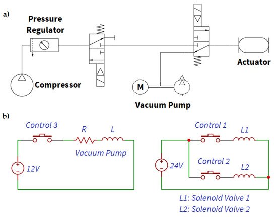
Pneumatic system. (
) Connection diagram. (
) Wiring diagram control. Signals 1, 2, and 3 are the cables that connect to the UR3 for control.
The pneumatic module is composed of two solenoid valves. One of the solenoid valves is used to connect the path that carries pressurized air to the gripper with the one from which air is extracted with the vacuum pump. The other solenoid valve connects the tube from the pressurized air reservoir with the inlet of the first solenoid valve and a blind tube. It operates as an open/close valve. Finally, a pressure regulator controls the pressure that is administered to the gripping tools. For compressed air, a compressor with a small tank is used, whereas an electric vacuum pump is used for vacuum generation.
2.1.1. Gripper 1
The first gripper, shown in
, is a pneumatic gripper based on the one commercialized by Soft Robotics [40]. They developed several configuration solutions depending on the application. In this work, the four-finger solution, with fingers symmetrically spaced around the center of the gripper, has been adopted.
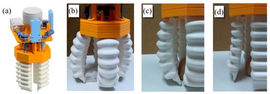
First gripper: (
) CAD model, (
) Gripper during the operation, (
) Fingers flexed, (
) and Fingers in extension.
The most important aspect of the design of fingers is its asymmetry along the lengthwise plane. This is necessary to allow movements. The inner side presents a flat surface with small reliefs that stick out to improve gripping capacity. The outer side presents six chambers that inflate when pressurized air is introduced inside, generating the contraction movement. Vice versa, creating a vacuum inside, they contract and generate the extension movement.
At one end, the finger has a section that allows it to be held at the base of the gripper, as well as allowing air to enter and exit the chamber. On the other end, a section with greater rigidity and with a triangular profile has been added to the finger. This provides a relatively straight section at the end of the finger to perform a better grip with the extremity. Fingers measure 11 cm in length and 4.5 cm in width.
For the creation of this prototype, two parts can be distinguished: manufacturing silicone fingers and the 3D printing of the rest of the pieces that form the base of the gripping tool (all 3D printed parts are made with the thermoplastic polyester PLA).
To obtain a silicone finger, a mold has been realized with 3D printing, as shown in
. It comprises three different parts: a male that provides the internal shape of the finger, and two females, which provide the exterior. The silicone used is the Silastic
3483, with a cure time of one hour.
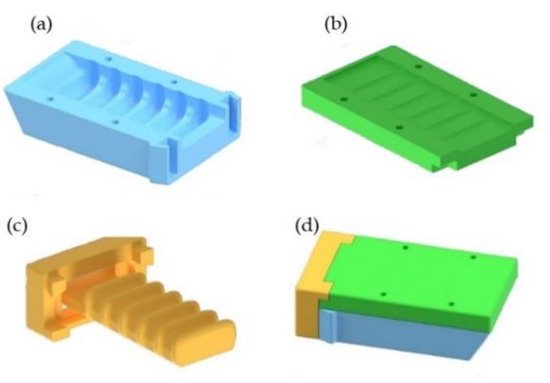
Mold for manufacturing silicone fingers: (
) Mold for inner side, (
) Mold for outer side, (
) Male mold, (
) The assembled mold.
This silicone allows getting the desired characteristics with regard to stiffness, while other silicones such as Ecoflex
00-30 have proved too soft for this application.
The working pressure of the gripping tools is around 2 bars.
2.1.2. Gripper 2
The second gripper, as shown in
, is also pneumatic and is based on the Versaball, which is a gripper produced by the company Empire Robotics Inc. [41]
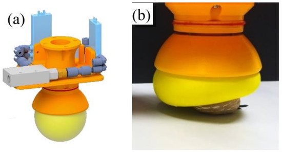
Second gripper: (
) CAD model of the gripper, (
) Gripper during the operation.
Its operation is based on the jamming process by which granular materials increase their viscosity when the density of particles increases.
The gripper presents a spherical chamber made of an elastomeric plastic membrane filled with granular material. It is possible to get the liquid and solid pseudo-states when pressurized air and vacuum are applied, respectively.
To grab an object, a small amount of air has to be introduced in the chamber so that the granular material acts similar to a liquid. Then, the gripper has to be pressed against the object, adapting the contents of the chambers to the outer shape of the object. Finally, the vacuum is created inside the chamber, in order to solidify its interior and maintain the shape of the object. As long as the vacuum is maintained, the object is held by the gripper. Subsequently, it is enough to fill the chamber with air again, to return to the “liquid” state and release the object. This method of gripping requires that the object size be approximately half of the diameter of the pneumatic chamber.
This gripper is composed of the previously described pneumatic module, a piece to join this module with the claw, two pieces to keep the filter in place, and two final pieces that hold the pneumatic camera.
As in the previous case, the pneumatic chamber is the basic element of the gripper. To realize it, a latex balloon of approximately 1-mm thickness and about 8 cm in diameter has been chosen. The chosen thickness provides the chamber with resistance against the abrasive action of the granular material and ensures that it is not damaged when coming into contact with objects. At the same time, a smaller thickness adapts easier to the small irregularities of the objects, besides gaining flexibility and elasticity.
Several options of granular materials have been tested, such as ground coffee, fine sand, and breadcrumbs. After testing ground coffee and breadcrumbs, it has experimentally been observed that with ground coffee, the chamber adapts much better to objects. This is the same material used in the research previously mentioned.
A filter is necessary to allow air to pass in both directions and maintain the granular material isolated from the pneumatic system. The filter is composed of a felt circle with the same diameter as the upper section of the base and a thickness of approximately one millimeter. The working pressure is around 1 bar.
2.2. Electromechanical System
The other two grippers are mechanical and use a 6 V DC motor with a reduction gearbox. To calculate the reduction, two parameters must be considered: the approximate closing time of the gripper and its generated torque.
For the third gripper, a great reduction ratio is necessary, since the torque generated by the motor must be enough to pull the three cables of the three fingers of the gripper simultaneously, so a reduction of 1:298 is necessary at least.
Indeed, a fourth gripper presents a spindle nut system that generates a suitable torque for this application. Thus, the reduction is chosen only based on the gripper closing time and is equal to 1:125.
The same structure is used to mount the motors on the two grippers, as the motor size is identical in spite of the different reduction ratio. This structure is composed of two parts: a base and an adapter for the robotic arm UR3. The base part houses the motor inside and is designed to be tightened to prevent its longitudinal displacement.
Finally, the simplified electrical scheme is showed in
. The LR group represents the DC motor, and the H bridge is composed of the four bipolar signals and the two control signals. These are the ones that connect to the input/output panel of the UR3.
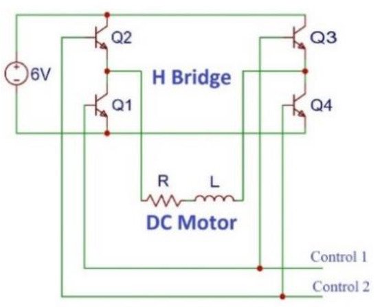
Wiring diagram of the electromechanical system.
2.2.1. Gripper 3
The first mechanical gripper, as shown in
, presents articulated fingers actuated by cables. When the cables are pulled by a motor connected to a pulley, the fingers are flexed.
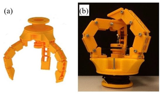
Third gripper: (
) CAD model of the gripper, (
) Real Gripper.
The shape that fingers adopt is a function of the object to be grasped; the links of the finger will adapt to the outer surface of the object.
Here, the number of fingers selected to achieve optimum grip is three, which are arranged at 120 degrees. To work properly, the three fingers must perform their movements simultaneously.
To carry out this movement, the three cables (one for each finger) are wound on the same pulley that collects or releases the cables, generating thus the flexion or extension of the fingers on the basis of the rotating direction.
The pulley represents a crucial part of the design, since it is responsible for the synchronization of the movement of fingers. It has an inner section in which a nut is inserted to fasten the pulley to the flat face of the motor shaft. The pulley is designed with a diameter that is small enough to generate a good torque for the application but large enough to be printed in 3D and not too fragile. It also has a duct with a circular section that connects the outer face of the pulley, where the cables are wound, with the underside of the pulley.
The three fingers are held on a base, and an adapter is used for the connection to the robot. Each finger comprises three base modules, one end, and a mount. Modules are joined with screws that allow their relative rotation. Each finger measures 12 cm in length and 2.5 cm in width.
2.2.2. Gripper 4
The fourth gripper, as shown in
, is based on the MultiChoice Gripper product manufactured by the FESTO
Company [42]. This design is based on the mechanics of the human hand where the thumb serves to impose an effort in the same direction but opposite orientation as the rest of the fingers. To adapt to different object typologies, the tool developed by FESTO is able to reorient the fingers and obtain different configurations. For example, for objects with round perimeter are placed with ternary symmetry. However, for objects with parallel faces, one finger is placed in opposition to the other two.
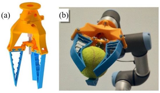
Fourth gripper: (
) CAD model of the gripper, (
) Gripper during the operation.
Nevertheless, for the reproduction of this prototype, this feature has been obviated to focus attention on the design of the fingers: passive structures capable of adapting to the objects that deform them. This gripping tool comprises three fingers of a flexible material. The fingers are triangular with thin walls and, longitudinally, they present a nucleus formed by rigid parts that prevent the walls of the finger from approaching. With this morphology, the tip remains approximately in the same place when trying to deform the finger, but the body bends around the object. This deformation of the finger allows it to adapt to the shape of the surface of the object with which it will make contact, and, thanks to its flexibility, it will deform before damaging it. In this case, the choice of the number of fingers that form the gripper could have been two, three, or four. The number three has been selected because the spindle mechanism makes the movement perfectly synchronized, and it is unnecessary to complicate the design by adding a fourth finger, although in some scenarios, it might be useful to have it.
The gripping tool consists of three flexible fingers and a rigid base. The fingers are made from the elastomeric thermoplastic produced by the company Recreus [43] called FilaFlex, and they measure 11 cm in length and 1.5 cm in width. The base is formed by two pieces: the main one on which the fingers are mounted and to which the motor is coupled, and a secondary one that serves to join the gripping tool with the UR3. Furthermore, the mechanical actuation is composed of a direct current motor, a coupler flexible, a spindle and a nut, and a handle to which the nut, the finger connector as well as the motor support are attached.
To generate the grip movement, each finger can be held with rotational joints at both ends of its base. By maintaining the position of the outer ends of the finger bases and changing the height of the inner ends, the opening and closing movement of the hand is achieved. This movement, which can be generated in many ways, is done with a spindle nut mechanism. A motor rotates the spindle, which causes the nut to move up and down when its rotation is prevented. The inner ends of the fingers are connected to the nut by connectors, which allow the possibility of movement while preventing the rotation of the nut.
The rigid sections that form the internal structure of the finger have been made with a wire. This wire has enough rigidity to allow the deformation of the finger but at the same time allow it to return to its initial position.
3. Experiments
Preparation of the Experiments
The objective of this work is to test the robustness of the gripping tools and their grasp stability. To test these parameters, an experiment has been designed in which the ability of the gripper to grip a certain object, to hold it while the robotic arm realizes a trajectory, and successively release it, is evaluated (as illustrated in
Figure 8). The test is deemed successful if the object does not fall either during the grip or the displacement and if the object is not damaged after gripping action.
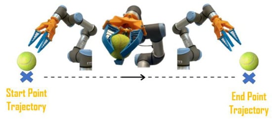
Test execution: the gripper picks up one of the twelve objects in a predetermined position and place it in the desired location.
Since one of the most important aspects is the capability of grippers to manipulate objects with different characteristics, i.e., different shape, rigidity, and fragility, twelve objects, as shown in
Figure 9, have been chosen for experimentation. Each of them presents different characteristics to represent a wider range of objects. The weight and dimensions of objects are limited by the capacity and dimensions of the grippers.
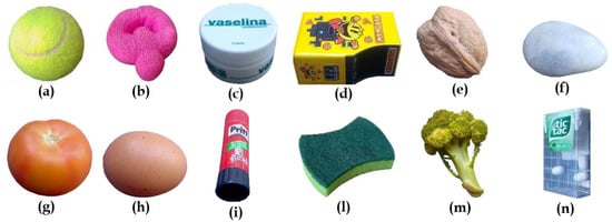
Selection of objects for experimentation with its identification number. (
) Tennis ball #1, (
) Screen Cleaner #2, (
) Vaseline Container #3, (
) Metallic Container #4, (
) Nut #5, (
) Rock #6, (
) Tomato #7, (
) Egg #8, (
) Glue Stick #9, (
) Dish Sponge #10, (
) Broccoli #11, and (
) Candy Box #12.
Objects are oriented in different ways to not facilitate any gripper. For example, object #9 (see
Table 1) is arranged vertically, whereas object #12 is arranged horizontally. In some cases, external elements have been used to ensure the correct positioning of the object, such as for the egg (#8) (as can be seen in
Figure 10or for the tennis ball (#1), which would have slipped once placed on the surface due to their physical characteristics.
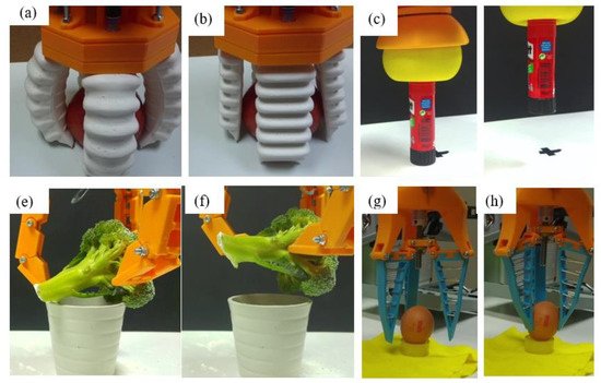
Test execution with Gripper 1 (
,
), Gripper 2 (
,
), Gripper 3 (
,
), Gripper 4 (
,
).
Selection of objects for experimentation. Each object has been assigned a number to facilitate the subsequent display of results (first column). The “Dimensions” column shows the significant dimensions of each object, and the “Weight” column shows the weight of the objects used in the experiments. In the last column “Relevant Aspects”, the aspects that differentiate each object from the others are highlighted.
| ID | Object | Dimensions | Weight | Relevant Aspects |
|---|
| 1 | Tennis ball | 70 mm diameter | 57.6 g | Quite rigid and with a rough surface |
| 2 | Screen Cleaner | 80 mm diameter 30 mm thickness |
12.8 g | Considerably soft and deformable |
| 3 | Vaseline container | 80 mm diameter 50 mm height |
147 g | Very smooth surface |
| 4 | Metallic container | 85 × 50 × 30 mm | 47.9 g | Prismatic form with some irregularities, smooth surface |
| 5 | Nut | 35 mm diameter 45 mm height |
14.4 g | Very small and lightweight |
| 6 | Rock | 25 × 15 × 10 mm | 12.9 g | The smallest object of the experiment |
| 7 | Tomato | 90 mm diameter 70 mm height |
229.6 g | The heaviest object of the experiment |
| 8 | Egg | 50 mm diameter 65 mm height |
71 g | Hard but very fragile |
| 9 | Glue stick | 25 mm diameter 100 mm height |
19.6 g | Svelte with irregularities at the ends |
| 10 | Dish sponge | 105 × 80 × 25 mm | 10.2 g | Considerably soft and deformable with a slightly stiffer surface |
| 11 | Broccoli | 90 mm diameter 120 mm height |
130.4 g | Irregular object that should not be deformed |
| 12 | Candy box | 60 × 35 × 15 mm | 7.9 g | Little gripping surface |
The experiment has been carried out in three different environments: normal, humid, and dusty. The normal environment is achieved without changing the properties of the environment. In this case, objects are not damp or dusty.
The experiment has been carried out in three different environments: normal, humid, and dusty. The normal environment is achieved without changing the properties of the environment. In this case, objects are not damp or dusty.The humid environment consists in moistening both the gripping tool and the object. The presence of humidity causes greater effects on some objects than on others, depending on the surface of the object and how much the water can wet it. For instance, while a plastic container with smooth walls may only slightly be affected by a humid environment, properties of a sponge, such as its weight and surface adhesion, greatly change in such an environment. Finally, the dusty environment is simulated by spreading a generous amount of flour both by the tool and by the object. The last two situations can occur in agriculture or in specific industrial processes.
The humid environment consists in moistening both the gripping tool and the object. The presence of humidity causes greater effects on some objects than on others, depending on the surface of the object and how much the water can wet it. For instance, while a plastic container with smooth walls may only slightly be affected by a humid environment, properties of a sponge, such as its weight and surface adhesion, greatly change in such an environment. Finally, the dusty environment is simulated by spreading a generous amount of flour both by the tool and by the object. The last two situations can occur in agriculture or in specific industrial processes. For each experiment, 20 repetitions have been performed. This means that for each object, 60 repetitions have been performed with each tool and twenty have been performed for each environment, which are 240 for each gripper and object. Being twelve objects, a total of 2880 repetitions are performed. InFor each experiment, 20 repetitions have been performed. This means that for each object, 60 repetitions have been performed with each tool and twenty have been performed for each environment, which are 240 for each gripper and object. Being twelve objects, a total of 2880 repetitions are performed. In
Figure 10, it is possible to see some captions of these experiments.
The time used for successful gripping is different for each of the grippers. In the case of Gripper 1, this time is in the range of 1–2 s, since the fingers must be inflated to a greater or lesser extent according to the object’s size. In the case of Gripper 2, this time is about 3 s, since it is necessary that the gripper first adjusts to the shape of the object to subsequently perform the vacuum. In the case of Gripper 3 and Gripper 4, this time is less than or equal to one second.
References
- Shintake, J.; Cacucciolo, V.; Floreano, D.; Shea, H. Soft Robotic Grippers. Adv. Mater. 2018, 30, 1707035.
- Hirose, S.; Umetani, Y. The development of soft gripper for the versatile robot hand. Mech. Mach. Theory 1978, 13, 351–359.
- Dollar, A.M.; Howe, R.D. A robust compliant grasper via shape deposition manufacturing. IEEE/ASME Trans. Mechatron. 2006, 11, 154–161.
- Manti, M.; Hassan, T.; Passetti, G.; D’Elia, N.; Laschi, C.; Cianchetti, M. A bioinspired soft robotic gripper for adaptable and effective grasping. Soft Robot. 2015, 2, 107–116.
- Odhner, L.U.; Jentoft, L.P.; Claffee, M.R.; Corson, N.; Tenzer, Y.; Ma, R.R.; Buehler, M.; Kohout, R.; Howe, R.D.; Dollar, A.M. A compliant, underactuated hand for robust manipulation. Int. J. Rob. Res. 2014, 33, 736–752.
- Liarokapis, M.; Dollar, A.M. Post-contact, in-hand object motion compensation for compliant and underactuated hands. In Proceedings of the 2016 25th IEEE International Symposium on Robot and Human Interactive Communication (RO-MAN), Columbia, NY, USA, 26–31 August 2016; pp. 986–993.
- Stuart, H.S.; Wang, S.; Cutkosky, M.R. Tunable contact conditions and grasp hydrodynamics using gentle fingertip suction. IEEE Trans. Robot. 2018, 35, 295–306.
- Mutlu, R.; Alici, G.; in het Panhuis, M.; Spinks, G.M. 3D printed flexure hinges for soft monolithic prosthetic fingers. Soft Robot. 2016, 3, 120–133.
- Gafford, J.; Ding, Y.; Harris, A.; McKenna, T.; Polygerinos, P.; Holland, D.; Moser, A.; Walsh, C. Shape deposition manufacturing of a soft, atraumatic, deployable surgical grasper. J. Med. Device. 2015, 7, 021006.
- Liu, C.-H.; Huang, G.-F.; Chiu, C.-H.; Pai, T.-Y. Topology synthesis and optimal design of an adaptive compliant gripper to maximize output displacement. J. Intell. Robot. Syst. 2018, 90, 287–304.
- Udupa, G.; Sreedharan, P.; Sai Dinesh, P.; Kim, D. Asymmetric bellow flexible pneumatic actuator for miniature robotic soft gripper. J. Robot. 2014, 2014, 902625.
- Galloway, K.C.; Becker, K.P.; Phillips, B.; Kirby, J.; Licht, S.; Tchernov, D.; Wood, R.J.; Gruber, D.F. Soft robotic grippers for biological sampling on deep reefs. Soft Robot. 2016, 3, 23–33.
- Hao, Y.; Gong, Z.; Xie, Z.; Guan, S.; Yang, X.; Ren, Z.; Wang, T.; Wen, L. Universal soft pneumatic robotic gripper with variable effective length. In Proceedings of the 2016 35th Chinese control conference (CCC), Chengdu, China, 27–29 July 2016; pp. 6109–6114.
- Guo, J.; Sun, Y.; Liang, X.; Low, J.-H.; Wong, Y.-R.; Tay, V.S.-C.; Yeow, C.-H. Design and fabrication of a pneumatic soft robotic gripper for delicate surgical manipulation. In Proceedings of the 2017 IEEE International Conference on Mechatronics and Automation (ICMA), Kagawa, Japan, 6–9 August 2017; pp. 1069–1074.
- Guo, J.; Elgeneidy, K.; Xiang, C.; Lohse, N.; Justham, L.; Rossiter, J. Soft pneumatic grippers embedded with stretchable electroadhesion. Smart Mater. Struct. 2018, 27, 55006.
- Li, Y.; Chen, Y.; Li, Y. Pre-charged pneumatic soft gripper with closed-loop control. IEEE Robot. Autom. Lett. 2019, 4, 1402–1408.
- Mantriota, G. Optimal grasp of vacuum grippers with multiple suction cups. Mech. Mach. Theory 2007, 42, 18–33.
- Krahn, J.M.; Fabbro, F.; Menon, C. A soft-touch gripper for grasping delicate objects. IEEE/ASME Trans. Mechatron. 2017, 22, 1276–1286.
- Brown, E.; Rodenberg, N.; Amend, J.; Mozeika, A.; Steltz, E.; Zakin, M.R.; Lipson, H.; Jaeger, H.M. Universal robotic gripper based on the jamming of granular material. Proc. Natl. Acad. Sci. USA 2010, 107, 18809–18814.
- Amend, J.; Cheng, N.; Fakhouri, S.; Culley, B. Soft robotics commercialization: Jamming grippers from research to product. Soft Robot. 2016, 3, 213–222.
- Guo, Z.; Sun, Z.; Li, X. Design and fabrication of pneumatic soft gripper. In Proceedings of the ASME 2018 International Mechanical Engineering Congress and Exposition, Pittsburgh, PA, USA, 9–15 November 2018.
- Mizushima, K.; Oku, T.; Suzuki, Y.; Tsuji, T.; Watanabe, T. Multi-fingered robotic hand based on hybrid mechanism of tendon-driven and jamming transition. In Proceedings of the 2018 IEEE International Conference on Soft Robotics (RoboSoft), Livorno, Italy, 24–28 April 2018; pp. 376–381.
- Fei, Y.; Wang, J.; Pang, W. A novel fabric-based versatile and stiffness-tunable soft gripper integrating soft pneumatic fingers and wrist. Soft Robot. 2019, 6, 1–20.
- Nguyen, P.H.; Sridar, S.; Amatya, S.; Thalman, C.M.; Polygerinos, P. Fabric-based soft grippers capable of selective distributed bending for assistance of daily living tasks. In Proceedings of the 2019 2nd IEEE International Conference on Soft Robotics (RoboSoft), Seoul, Korea, 14–18 April 2019; pp. 404–409.
- Nassour, J.; Hamker, F. Enfolded textile actuator for soft wearable robots. In Proceedings of the 2019 IEEE International Conference on Cyborg and Bionic Systems (CBS), Munich, Germany, 18–20 September 2019; pp. 60–65.
- Monkman, G. Electroadhesive microgrippers. Ind. Robot An Int. J. 2003, 30, 326–330.
- Shintake, J.; Rosset, S.; Schubert, B.; Floreano, D.; Shea, H. Versatile soft grippers with intrinsic electroadhesion based on multifunctional polymer actuators. Adv. Mater. 2016, 28, 231–238.
- Shea, H.R.; Jun, S.; Dario, F. Soft Compliant Gripper for Safe Manipulation of Extremely Fragile Objects; SPIE: Bellingham, WA, USA, 2016.
- Song, S.; Majidi, C.; Sitti, M. Geckogripper: A soft, inflatable robotic gripper using gecko-inspired elastomer micro-fiber adhesives. In Proceedings of the 2014 IEEE/RSJ International Conference on Intelligent Robots and Systems, Chicago, IL, USA, 14–18 September 2014; pp. 4624–4629.
- Glick, P.; Suresh, S.A.; Ruffatto, D.; Cutkosky, M.; Tolley, M.T.; Parness, A. A soft robotic gripper with gecko-inspired adhesive. IEEE Robot. Autom. Lett. 2018, 3, 903–910.
- Shintake, J.; Schubert, B.; Rosset, S.; Shea, H.; Floreano, D. Variable stiffness actuator for soft robotics using dielectric elastomer and low-melting-point alloy. In Proceedings of the 2015 IEEE/RSJ International Conference on Intelligent Robots and Systems (IROS), Hamburg, Germany, 28 September–3 October 2015; pp. 1097–1102.
- Xu, L.; Gu, G. Bioinspired Venus flytrap: A dielectric elastomer actuated soft gripper. In Proceedings of the 2017 24th International Conference on Mechatronics and Machine Vision in Practice (M2VIP), Auckland, New Zealand, 21–23 November 2017; pp. 1–3.
- Guo, J.; Xiang, C.; Rossiter, J. A soft and shape-adaptive electroadhesive composite gripper with proprioceptive and exteroceptive capabilities. Mater. Des. 2018, 156, 586–587.
- Pourazadi, S.; Bui, H.; Menon, C. Investigation on a soft grasping gripper based on dielectric elastomer actuators. Smart Mater. Struct. 2019, 28, 35009.
- Wang, Z.; Chathuranga, D.S.; Hirai, S. 3D printed soft gripper for automatic lunch box packing. In Proceedings of the 2016 IEEE International Conference on Robotics and Biomimetics (ROBIO), Qingdao, China, 3–7 December 2016; pp. 503–508.
- Marchese, A.D.; Katzschmann, R.K.; Rus, D. A recipe for soft fluidic elastomer robots. Soft Robot. 2015, 2, 7–25.
- Pettersson, A.; Davis, S.; Gray, J.O.; Dodd, T.J.; Ohlsson, T. Design of a magnetorheological robot gripper for handling of delicate food products with varying shapes. J. Food Eng. 2010, 98, 332–338.
- Hamid, A.M.B.; Makhdoomi, M.R.; Saleh, T.; Bhuiyan, M. Development of a Shape Memory Alloy (SMA) Based Assistive Hand. Adv. Mater. Res. 2015, 1115, 454–457.
- Kang, L.; Seo, J.-T.; Kim, S.-H.; Kim, W.-J.; Yi, B.-J. Design and Implementation of a Multi-Function Gripper for Grasping General Objects. Appl. Sci. 2019, 9, 5266.
- Soft Robotics Inc. Available online: (accessed on 20 February 2021).
- Empire Robotics. Available online: (accessed on 20 February 2021).
- Festo MultiChoiceGripper. Available online: (accessed on 20 February 2021).
- Recreus Recreus. Available online: (accessed on 20 February 2021).