In inverter-dominated AC grids, impedance-based analysis methods are proving to be more powerful than traditional state-space-based analysis methods. Even the conventional parameters and standards used to estimate the stability of generators and stronger grids cannot fully capture the dynamics of weaker, inverter-dominated grids. It then stands to reason that system impedances that are commonly used to analyze DC systems will be useful in the analysis of grid-forming inverters in these hybrid systems. To understand the value of studying the impedances of inverters and other elements in weak AC grids, this article reviews and describes the various ways in which impedance-based analyses can be used to define, assess, and improve the performance of grid-forming inverter controllers.
- grid-forming
- inverter
- control design
- impedance
- stability
1. Introduction
The increased use of power electronic converters to interface loads and sources has led to a significant shift in the dynamics and behavior of various grid components. Not only are the response times faster, but the overall grid is also weaker with lower inertia and higher impedance, so the concerns and conditions used as the foundation for control design become less relevant in inverter-based grids [1][2]. Hence, the analysis methods developed for synchronous machines need to be replaced by a new paradigm for assessing system stability and calculating parameters for converter control [3]. Impedance-based analysis methods are better suited to capture the high-frequency dynamics and resonant interactions created by the presence of power electronic elements [4].
The increased use of power electronic converters to interface loads and sources has led to a significant shift in the dynamics and behavior of various grid components. Not only are the response times faster, but the overall grid is also weaker with lower inertia and higher impedance, so the concerns and conditions used as the foundation for control design become less relevant in inverter-based grids [1,2]. Hence, the analysis methods developed for synchronous machines need to be replaced by a new paradigm for assessing system stability and calculating parameters for converter control [3]. Impedance-based analysis methods are better suited to capture the high-frequency dynamics and resonant interactions created by the presence of power electronic elements [4].
Grid-following (or grid-tied) inverters are more commonly analyzed using impedance-based and other analysis methods than grid-forming inverters, which have only recently gained traction and interest [5][6][7][8]. Furthermore, the conclusions obtained from the analysis of grid-following inverters cannot be completely applied to grid-forming inverters because, in the absence of a stiff grid or synchronous generators the interaction of the inverter with other inverters, loads and grid elements becomes much more complicated [9][10]. Inverters controlled in a decentralized manner (which is the case for most grid-forming control strategies) are greatly affected by sudden load changes, which can cause power sharing instability in the low frequency range. The fast dynamics in the inner control loops and high order filters of parallel inverters interact with each other and cause harmonic resonance in the high frequency range [11]. Non-linearities of loads and inverters, as well as multiple resonance modes of network impedance, in inverter-based microgrids make power quality control more challenging [12].
Grid-following (or grid-tied) inverters are more commonly analyzed using impedance-based and other analysis methods than grid-forming inverters, which have only recently gained traction and interest [5,6,7,8]. Furthermore, the conclusions obtained from the analysis of grid-following inverters cannot be completely applied to grid-forming inverters because, in the absence of a stiff grid or synchronous generators the interaction of the inverter with other inverters, loads and grid elements becomes much more complicated [9,10]. Inverters controlled in a decentralized manner (which is the case for most grid-forming control strategies) are greatly affected by sudden load changes, which can cause power sharing instability in the low frequency range. The fast dynamics in the inner control loops and high order filters of parallel inverters interact with each other and cause harmonic resonance in the high frequency range [11]. Non-linearities of loads and inverters, as well as multiple resonance modes of network impedance, in inverter-based microgrids make power quality control more challenging [12].
2. Grid-Forming Control
Voltage source inverters are generally used for interfacing distributed generation with the grid, while current source inverters are largely used in motor drive applications [13]. However, for grid-connected operation, voltage source inverters are transformed into current sources to feed active and reactive power to the grid. As a virtual current source, these inverters require a stiff grid and prior knowledge of system loads. Even grid-supporting inverters, which do not necessarily need a synchronous generator to impose a stiff frequency, are normally only used to balance the voltage and frequency of the grid [14]. Moreover, current-controlled inverters cannot respond instantly to load change. Generally, in isolated microgrids, there is only one grid-forming inverter to establish the grid voltage (as the leader), while the other inverters function in grid-following mode (as followers) [15][16].
Voltage source inverters are generally used for interfacing distributed generation with the grid, while current source inverters are largely used in motor drive applications [24]. However, for grid-connected operation, voltage source inverters are transformed into current sources to feed active and reactive power to the grid. As a virtual current source, these inverters require a stiff grid and prior knowledge of system loads. Even grid-supporting inverters, which do not necessarily need a synchronous generator to impose a stiff frequency, are normally only used to balance the voltage and frequency of the grid [25]. Moreover, current-controlled inverters cannot respond instantly to load change. Generally, in isolated microgrids, there is only one grid-forming inverter to establish the grid voltage (as the leader), while the other inverters function in grid-following mode (as followers) [27,28].
3. Impedance-Based Analysis for Controller Design
The two major analysis tools used for power electronics-based grids are the state-space method and impedance-based method [17]. These two tools have certain advantages and disadvantages and can be used in a complementary manner. The state-space model tends to be more comprehensive by providing deep insight into the dynamics of the whole system but requires extensive knowledge of the system and control parameters for model formulation and validation [18].The details for each component in (heterogeneous) inverter-based grids are not easily available to perform a global stability analysis in advance. State-space methods also do not allow the local analysis of individual elements to support controller development [19].
The two major analysis tools used for power electronics-based grids are the state-space method and impedance-based method [39]. These two tools have certain advantages and disadvantages and can be used in a complementary manner. The state-space model tends to be more comprehensive by providing deep insight into the dynamics of the whole system but requires extensive knowledge of the system and control parameters for model formulation and validation [40].The details for each component in (heterogeneous) inverter-based grids are not easily available to perform a global stability analysis in advance. State-space methods also do not allow the local analysis of individual elements to support controller development [41].
On the other hand, although impedance-based models cannot be used to identify the reasons for underdamped or unstable modes, they are easier to formulate and validate using direct measurements and without complete knowledge of the system [10]. Moreover, as the attention shifts towards higher frequency dynamics with the proliferation of more grid-forming inverters in the grid, impedance-based analysis will prove to be more useful than state-space methods as they are able to include the impact of interactions between inverter and grid impedances in the analysis [20].
On the other hand, although impedance-based models cannot be used to identify the reasons for underdamped or unstable modes, they are easier to formulate and validate using direct measurements and without complete knowledge of the system [10]. Moreover, as the attention shifts towards higher frequency dynamics with the proliferation of more grid-forming inverters in the grid, impedance-based analysis will prove to be more useful than state-space methods as they are able to include the impact of interactions between inverter and grid impedances in the analysis [42].
3.1. DC-Side Stability
Most analyses of AC power inverters connected to DC sources normally consider an infinite DC source behind the DC-link and completely ignore the DC-link dynamics. This leads such analyses to focus solely on the AC output behavior or the impact of the input impedance on the AC output, which results in an incomplete understanding of the inverter behavior, as well as an inefficient design. As more DC power system-based control and analysis methods are applied to AC grids, attention must also be paid to the DC dynamics behind the AC inverter.
The major impedance-based stability criteria used in DC power systems are described in Reference [
]. The most common stability issue in DC (micro)grids is the negative incremental resistance behavior of constant power loads [
]. The constant power loads usually analyzed in these studies are DC and AC motor loads connected to the grid through an inverter which is tightly controlled [
47]. However, source inverters connected to DC sources, depending on the control feedback structure can also behave like constant power loads from the perspective of the upstream DC source. It is this behavior that causes unstable interactions between parallel inverters, even when each inverter is designed to be independently stable (Figure 1).
]. However, source inverters connected to DC sources, depending on the control feedback structure can also behave like constant power loads from the perspective of the upstream DC source. It is this behavior that causes unstable interactions between parallel inverters, even when each inverter is designed to be independently stable.
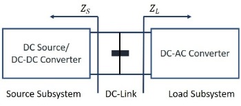
Figure 1. Source-load subsystem model for minor loop gain-based stability criteria.
Figure 3. Source-load subsystem model for minor loop gain-based stability criteria.
3.2. AC-Side Stability
Current-controlled voltage source inverters commonly used for grid-tied operation
are incapable of quickly responding to changes in load. This control is sufficient to extract a constant amount of power and make the inverter impervious to grid disturbances. However, trying to maintain the stability of an inverter during disturbances can also make the inverter unresponsive to changing load conditions. Maintaining stable operation while providing sufficient load support is a challenging task, especially for weak grids with poor grid stiffness. Although controllers with multiple feedback loops are employed for their ability to limit the output voltage and current, these loops tend to slow down the controller response, making them unable to achieve fast frequency or inertia response which are intrinsic to synchronous generators [
53]. These types of controllers also need to be retuned with changing grid conditions to achieve the intended control characteristics which can be achieved using an impedance-based approach as described in Reference [
]. These types of controllers also need to be retuned
with changing grid conditions to achieve the intended control characteristics which can be achieved using an impedance-based approach as described in Reference [
].
3.3. Load Disturbance Compensation
Since the inner control loop removes disturbances in the output of the outer loop, a cascaded control structure can increase the stability and the response speed of the outer loop. Nevertheless, cascaded control cannot respond to any disturbance outside the control loop which creates errors in the control loop variable. Hence, feedforward control is normally added as a correcting signal to modulate the output of the control loop and cancel out the load disturbance [
Since the inner control loop removes disturbances in the output of the outer loop, a
cascaded control structure can increase the stability and the response speed of the outer loop. Nevertheless, cascaded control cannot respond to any disturbance outside the control loop which creates errors in the control loop variable. Hence, feedforward control is normally added as a correcting signal to modulate the output of the control loop and cancel out the load disturbance [
]. In this way, the load disturbance compensation by feedforward control complements the supply disturbance compensation of the cascaded feedback loop control and improves its transient stability. In this case, the control system poles are determined by the feedback loop gains, while the zeros are determined by the feedforward loop gains.
3.4. Cross-Coupling in Different Domains
Cross-coupling in the synchronous domain is caused by asymmetrical control dynamics along the axes and the presence of inductance and capacitance in output filters and grid impedance whereas cross-coupling in the sequence domain is attributed to system imbalances in the positive or negative sequence domains and the mirror frequency effect [
].
3.5. Improved Power Sharing
The flow of circulating currents between inverters reduces their power sharing efficiency and can also lead to instability in severe cases. Circulating currents between inverters are usually a result of the mismatch at the output terminals of connected inverters, which can be a small difference in output voltage magnitude or frequency, disparate output/line impedance, or phase error between outputs. Active and reactive power sharing accuracy can be improved by adjusting or shaping the output impedance of each converter to minimize the circulating current between them [
]. Impedance analysis can also be used to determine power transfer stability limits for converters interfaced with DC sources like energy storage and solar arrays that are connected to weak AC grids [
].
4. Application of Impedance Analysis to Droop Control
The impedance analysis of a droop-controlled grid-forming inverter along with simulation results will demonstrate the application of the aforementioned impedance-based analysis methods to judge different aspects of the controller performance and its interaction with the load in the absence of any influence from an additional parallel inverter. The controller is analyzed using MATLAB and then simulated in an inverter-load system using Simulink (Figure 2).
The impedance analysis of a droop-controlled grid-forming inverter along with simulation results will demonstrate the application of the aforementioned impedance-based analysis methods to judge different aspects of the controller performance and its interaction with the load in the absence of any influence from an additional parallel inverter. The controller is analyzed using MATLAB and then simulated in an inverter-load system using Simulink.
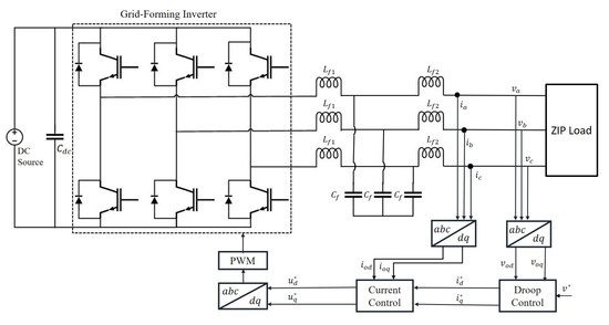
Figure 26.
Simulink model of droop-controlled inverter with LCL filter connected to a ZIP load.
5. Conclusions
Impedance-based models are capable of representing controller dynamics, resonant behavior, and interactions with grid elements for a grid-forming inverter, thus simplifying the system analysis on both DC and AC sides. These modeling and analysis techniques can help identify desirable input and output impedance characteristics. This enables a localized analysis of inverter controllers by characterizing the impacts of and interactions with other grid elements, unlike state-space-based analysis methods.
The input and output impedances of an inverter can be actively shaped by varying the control structure, using feedforward compensation, and adding virtual impedance in the control loop to damp resonances and enhance disturbance rejection. While passive impedance shaping techniques increase the overall cost of the system, active shaping methods can add control delays and decrease the robustness of the controller. Besides, the objectives of different active shaping techniques may conflict with each other. The impact of these shaping techniques on each other, as well as on the control dynamics, can also be studied by impedance-based methods. Impedance-based modeling and analysis are, thus, powerful tools in inverter control design which is illustrated by applying these methods to analyze a droop controller in a low-voltage inverter-based grid.
Impedance-based models are capable of representing controller dynamics, resonant behavior, and interactions with grid elements for a grid-forming inverter, thus simplifying the system analysis on both DC and AC sides. These modeling and analysis techniques can help identify desirable input and output impedance characteristics. This enables a localized analysis of inverter controllers by characterizing the impacts of and interactions with other grid elements, unlike state-space-based analysis methods.
The input and output impedances of an inverter can be actively shaped by varying
the control structure, using feedforward compensation, and adding virtual impedance in the control loop to damp resonances and enhance disturbance rejection. While passive impedance shaping techniques increase the overall cost of the system, active shaping methods can add control delays and decrease the robustness of the controller. Besides, the objectives of different active shaping techniques may conflict with each other. The impact of these shaping techniques on each other, as well as on the control dynamics, can also be studied by impedance-based methods. Impedance-based modeling and analysis are, thus, powerful tools in inverter control design which is illustrated by applying these methods to analyze a droop controller in a low-voltage inverter-based grid.