Harmonic Radio Frequency Identification (RFID) system operates at two different frequencies for uplink and downlink communication unlike conventional RFID systems. Operating at two frequencies provides many operational advantages over RFID system.
- RFID
- harmonic
1
1. Introduction
Radio Frequency Identification (RFID) technology has emerged as a successful technology for tagging, tracking, sensing, and locating objects [1][2][3] in different sectors such as healthcare, retail, logistics, and agriculture [4][5][6]. RFIDs can work at different frequencies, starting from a low frequency (LF) band to microwave ISM (Industrial, Scientific, and Medical) bands with or without on-board power source such as batteries. Active RFIDs are battery powered [7], whereas passive type RFIDs harvest energy from the incoming Electromagnetic (EM) field. Active RFIDs can have a very long read range of 100 m and longer, in some cases, more than 1 km [8][9], whereas the read range of a passive RFID is limited by their energy harvesting capability [10]. A passive LF RFID is used for short range communication (∼5 cm), whereas the ultra high frequency (UHF) passive RFID has a longer read range (∼6–8 m). The exclusion of batteries in passive RFIDs allows them to have a small form factor and leads to lower cost, and makes them easier to adopt for many applications. Advances in RFID have been possible due to state-of-the-art CMOS fabrication technology, development of printing techniques for low cost and bulk manufacturing, and development of required software for scalable business operation [11]. The RFID market has become a multi-billion dollar industry and continues to grow.Beyond object tagging, demand for RFIDs is increasing in many other applications such as sensing and localization. Food packages tagged with RFID-based sensors can help in dramatically reducing food wastage by seamless monitoring of food quality across the food supply chain [12][13]. Another important growing application of RFID is in the localization of products. Localization of specific RFID tagged objects in retail stores, sorting facilities, warehouses, and resource management facilities can automate the handling process and minimize the possibility of misplaced items [14][15][16]. Due to a shorter read range of passive RFIDs, an unmanned vehicle with an RFID reader has been proposed to localize desired tagged objects at large facilities for complete automation [14][17][18]. Usually, the received signal strength indicator (RSSI) and phase of return RF signal are measured by a conventional RFID reader to estimate a tag’s location. This method does not provide good accuracy, especially when many tags are co-located. Furthermore, reflection from nearby scatterers, such as metal racks and shelves, can induce multipath fading and hence degrade the localization accuracy. To overcome this challenge, different measurement methods such as spatial-temporal phase profiling (STPP) for relative object localization [19], Bayesian filter, and a variable power RFID model (BFVP) [20] have been proposed for improved localization accuracy. Those methods were demonstrated in complex real-world applications such as locating objects in a mock apparel store, misplaced books in a library, or determining the baggage order at an airport.Apart from the multipath effect, background clutter is a major challenge for RFID technology as it reduces the desired read range. Clutter is background reflection from nearby objects and it can overshadow the desired signal coming from the RFIDs and thus degrade the signal-to-noise ratio (SNR) at the reader [21]. In addition, strong clutter can significantly reduce the localization accuracy [22]. Most of the proposed solution to reduce the clutter and multipath effects are dependent on heavy computation at the reader and in some cases requires a detailed understanding of the operating environment. Recently, a new type of RFID, harmonic RFID, was proposed to mitigate the clutter and localization challenges [23][24]. In contrast to the conventional RFID system, the harmonic RFID system uses two different frequencies (fundamental and its harmonic) for down- and up-link communication between the RFID reader and tag. This review article presents the fundamental advantage, progress, applications, and future harmonic RFID trend.
2. IntDroducawback of Conventional RFID
Although conventional RFID has many advantages, there are also certain drawbacks that arise due to the fundamental operating principle of RFID. The primary two drawbacks of conventional RFID are: (a) clutter, and (b) localization. The drawbacks are discussed first from a system operation point of view and the advantage of harmonic RFID in mitigating those drawbacks is elaborated later.
2.1. Clutter
Clutter is described as an unwanted signal, which can obscure the desired signal and hence diminish the system performance. The clutter source in conventional RFID can arise from several places: (1) self-jamming due to mismatch at the antenna port, (2) multi-reader jamming when multiple RFID readers are transmitting simultaneously and one can jam the other, (3) reflection from nearby objects [25][26][27]. The primary clutter objects are usually different in different applications. For example, the primary clutter object for a body area network (BAN) based sensor or sensor monitoring body vitals is the biological body [28]. In underground object tagging, the ground is a source of strong clutter [29][30]. Similarly, in industrial environments, metal objects are a source of clutter [24]. The different clutter sources are shown pictorially for multiple scenarios in Figure 1.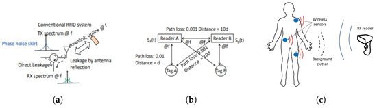 Figure 1. Different sources of clutter (a) self-jamming [25], (b) multi-reader jamming [25], [Reproduced with permission from Y. Ma, A passive broadband harmonic Radio Frequency Identification (RFID) platform; published by IEEE, 2016.] (c) Reflection from human body in a body area network (BAN) sensor [27]. [Reproduced with permission from S. Mondal, Scope and application of harmonic RFID for implanted body area network; published by IEEE, 2020].In [24], a mathematical formulation is provided to show how the clutter phase noise can overshadow the low power tag return modulation signal. Furthermore, experimentally, it was demonstrated that a conventional RFID read rate reduces in the presence of a clutter source. The read rate was directly correlated to the signal-to-clutter ratio (SCR), and hence, the read rate can be analyzed to monitor the clutter effect. Clutter that originated due to reflection from the metallic scatterer was measured in [27] using the conventional RFID front end. In the reader front end, the baseband amplifier should be of very low noise to measure the system phase noise [31]. If the tag returned signal is of very low power and low frequency, it can get buried under the clutter phase noise. The reader circuit and the measured phase noise response in the absence and presence of the clutter source are shown in Figure 2.
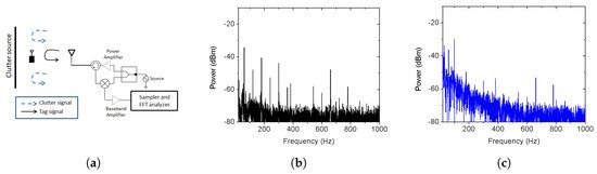 Figure 2. (a) The reader circuit to measure the clutter, (b) clutter phase noise in presence of an absorber, and (c) clutter phase noise in the presence of a clutter source [27]. [Reproduced with permission from S. Mondal, Scope and application of harmonic RFID for implanted body area network; published by IEEE, 2020].
2.2. Localization
RFID has become widely accepted in enterprise supply chain management systems as it improves the efficiency of inventory tracking. In the supply chain, RFID tagged object localization using RF signal is a desired feature. The RF localization is primarily done using RSSI, or phase information, or a combination of both [32][33]. However, precise localization in a conventional RFID system is a challenge due to (a) multipath effect, (b) undesired interference, and (c) presence of multiple RFID tags [34]. In RSSI-based localization, the signal attenuation level is monitored and the distance is estimated from Friis transmission equation. The multipath effect is stronger in this method due to the received signal power level measurement. In phase-based measurement, the phase of the arrival of the backscattered signal is measured. However, accurate phase-based localization is possible when the bandwidth is wider, which is difficult for a conventional RFID system with only 30 MHz bandwidth. Interference among multiple readers is possible and can contribute to distance uncertainty. Furthermore, when the RFID tags are densely populated, it becomes difficult to remove localization ambiguity among the tags. The inherent problem lies in the frequency of operation and the localization ambiguity reduces with an increase in the operating frequency.
2.3. Harmonic RFID as a Solution
Clutter and localization issues can be substantially mitigated by employing a harmonic RFID solution. The harmonic RFID tag and reader operates at two different frequencies: (a) reader to tag downlink at the fundamental frequency, and (b) tag to reader uplink at the harmonic frequency. In a harmonic RFID, the tag generates harmonic of the reader transmitted RF signal and uses that as a carrier for modulation. Harmonic RFID has an advantage in a cluttered environment as the clutter appears at the fundamental frequency and the tag return signal is at the harmonic frequency. Hence, the clutter cannot obscure the desired signal, unlike the conventional RFID system.Similarly, the localization is also improved when harmonic RFID is used. In [35], it was experimentally demonstrated that as the phase information is contained within the second harmonic, interferences and phase errors caused by direct reflections of the interrogating signal were greatly reduced. In addition, the phase information is better preserved in the harmonic operation and immune to background interference, as demonstrated in [36]. Simultaneously, as the readers transmit only the fundamental frequency, the reader-to-reader interference will be greatly reduced. Additionally, as the harmonic frequency reduces the operating wavelength, the localization accuracy is significantly enhanced [37]. Two different cases of harmonic phase based localization and sensing are shown in Figure 3.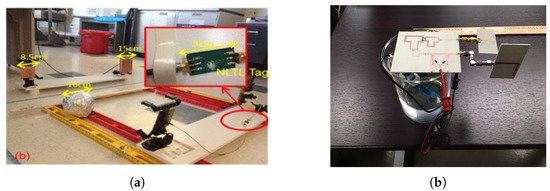 Figure 3. (a) Harmonic phase based localization in the presence of a scatterer [35] [Reproduced with permission from Y. Ma, Accurate indoor ranging by broadband harmonic generation in passive NLTL backscatter tags; published by IEEE, 2014]. (b) Harmonic phase-based sensing with better immunity to background clutter [36]. [Reproduced with permission from S. Mondal, A wireless passive pH sensor with clutter rejection scheme; published by IEEE, 2019].
3. Harmonic RFID
The methodology to generate low conversion loss and an efficient harmonic are discussed in detail in the previous sections. In this section, the different methods to realize a complete harmonic RFID tag using those harmonic generators will be discussed. Similar to the conventional RFID system, there are primarily two types of harmonic RFID: (a) chipless harmonic RFID, where the ID bits are encoded in the frequency domain, and (b) chip-based harmonic RFID, where the ID bits are encoded in the time domain. The advantage of chipless harmonic RFID is the simplicity of the circuit. However, the bandwidth requirement is significantly large for chipless harmonic RFIDs with a higher number of ID bits. On the other hand, the chip-based harmonic RFID with ID bits in the time domain has a significantly complex circuit, but the bandwidth usage is extremely low. The trend in passive harmonic RFID systems is summarized in Figure 4.
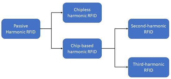
Figure 4. Recent trend in passive harmonic RFID systems.
3.1. Chipless Harmonic RFID
One-bit to multi-bit chipless harmonic RFID tags have been proposed earlier [38][39]. The chipless harmonic tags consist of two antennas resonating at fundamental and harmonic frequencies and a Schottky diode-based harmonic generator. In [38], the one-bit tag used a Schottky diode, HSMS-2850, for harmonic generation. The tag used two antennas at the fundamental and harmonic frequencies for signal reception and reply from the harmonic RFID reader. A read range of approximately 1 m was achieved using this setup. In [39], a multi-bit harmonic RFID tag was proposed using BAT 15-03 Schottky diode and resonators in different configurations. One configuration was to use split-ring resonators as band stop filters at the desired frequency spectrum to encode the ID. A wideband antenna was required to cover the complete bandwidth of operation. Another configuration was to use multiple dipoles resonating at the desired frequency band pairs, fundamental and harmonic. One such dipole pair represents one-bit in this configuration. As the number of bits is increased, the required number of antennas increases significantly, making 2nantennas a requirement for n bits. Other chipless harmonic RFID work exploited the idea of information encoding within the phase information [40]. In this work, the proposed tag first generates the harmonic of the received signal then splits it into two orthogonal channels. The orthogonal channels were realized using two orthogonally polarized antennas.Although the chipless tags have a very simple architecture, most of them have the fundamental limitation of the number of ID bits encoding and many proof-of-concept works demonstrate only single bit encoding [29][41][42]. Likewise, the harmonic RFID reader architecture is also simple in nature. The harmonic reader primarily contains a transmitter at fundamental frequency and a power level detector (like spectrum analyzer) at the desired harmonic frequency. A schematic of a chipless harmonic RFID system with a tag and reader is shown in Figure 5.
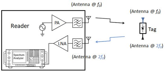
Figure 5. Schematic diagram of a chipless harmonic RFID tag and reader system with two antennas.
3.2. Chip-Based Harmonic RFID
Apart from chipless harmonic RFID, other works on harmonic RFID are based on chip integrated RFID. In addition, under chip integrated RFID, there are primarily two lines of work: (a) second harmonic RFID and (b) third harmonic exploitation of conventional RFID. First, the second harmonic RFID system is described, followed by harmonic RFID using conventional RFIDs.
3.2.1. Second Harmonic RFID
This type of harmonic RFID is a balanced integration of functional units of conventional chip-based RFID and harmonic generators. Conventional RFID uses fundamental functional blocks as: (a) energy harvester, (b) digital circuit for ID generation, and (c) antenna. In a harmonic RFID system, an additional building block of a harmonic generator is added. Furthermore, as harmonic RFID uses two frequency bands for communication, multi-band or multiple antennas are required for a harmonic RFID tag and reader. Different harmonic RFID configurations were proposed in [24][25][43]. In [25], a fully functional first harmonic RFID tag was proposed. The proposed tag used an NLTL-based harmonic generator and operated within the 700 to 1200 MHz band for the fundamental frequency. A schematic block diagram of the tag circuit and implementation are shown in Figure 6. The proposed harmonic RFID tag requires two broadband antennas for NLTL impedance matching at fundamental and harmonic frequencies.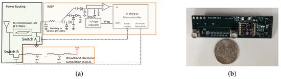 Figure 6. (a) Schematic block diagram of the harmonic RFID, and (b) implementation of the harmonic RFID circuit as in [25]. [Reproduced with permission from Y. Ma, A passive broadband harmonic RFID platform; published by IEEE, 2016].In [24], an 8-bit harmonic RFID tag was proposed for a 434 and 868 MHz frequency duplex as the fundamental and harmonic frequency, respectively. Similar to [25], Ref. [24] also required two antennas. However, in [24] broadband antenna was no longer required and hence the harmonic RFID tag could be miniaturized with small feature size antennas both at input and output. The schematic block diagram and the circuit implementation of harmonic RFID are shown in Figure 7.
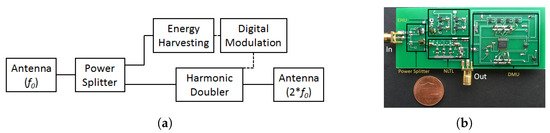 Figure 7. (a) Schematic block diagram of the harmonic RFID, and (b) implementation of the harmonic RFID circuit as in [24]. [Reproduced with permission from S. Mondal, A passive harmonic RFID tag and interrogator development; published by IEEE, 2019].The most recent harmonic RFID tag reported in [43] also operates on 434 MHz and 868 MHz frequency duplex as fundamental and harmonic frequency. The reported harmonic tag uses a dual frequency band single antenna and hence greatly reduces the tag real estate area [44]. The tag architecture also reduces the number of components compared to [24][25]. In addition to standard conventional RFID components, the only extra component required in [43] is the harmonic generator. To the best of our knowledge, the harmonic RFID tag reported in [43] will require the least tag area for the same frequency operation among the reported chip-based second harmonic RFID tags. The schematic block diagram and the circuit implementation of harmonic RFID are shown in Figure 8. In addition to miniaturized tag dimension, the harmonic RFID can harvest energy at both modulation states, unlike conventional RFID, which cannot harvest energy when the antenna is shorted.
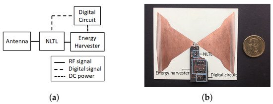 Figure 8. (a) Schematic block diagram of the harmonic RFID, and (b) implementation of the harmonic RFID circuit as in [43]. [Reproduced with permission from S. Mondal, A continuous-mode single-antenna harmonic RFID tag; published by IEEE, 2020].The second harmonic RFID reader can be a heterodyne or a homodyne design. A heterodyne receiver architecture was proposed in [45], where the reference clock is required to demodulate the tag signal. In [24], a homodyne receiver architecture was proposed for tag signal demodulation. The antenna and filter system at the receiver operates as a bandpass filter (BPF) to prevent undesired signal effectively at the demodulated output for homodyne receiver.
3.2.2. Harmonic Exploitation of Conventional RFID
In parallel to the second harmonic RFID system development, another popular approach was to exploit the third harmonic generation from the conventional RFID tag [46][47][48][49][50][51][52][53]. In this method, the antiparallel combination of detector diodes in a charge pump configuration was leveraged towards third harmonic generation from a conventional RFID. A conventional RFID tag would backscatter modulated the third harmonic along with the modulated fundamental carrier. In the literature, the generated third harmonic is exploited in two ways: (a) harvest the third harmonic and enhance the read range [50][51]; and (b) use the third harmonic for tag-to-reader link communication [49][52][53]. The implementation of the conventional tag and backscattering third harmonic is shown in Figure 9. A dual band antenna, resonating at both the fundamental and third harmonic, is required for third harmonic exploitation of the conventional RFID tag. In [52][53], impedance matching of the antenna was performed for maximum power transfer at both frequencies. The implemented conventional tag in [52] demonstrated digital data transfer at the harmonic for the first time. A comparable read range was achieved when compared to the same tag IC used at the fundamental frequency implementation. Redesign of the tag IC for harmonic generation will allow for enhanced read range.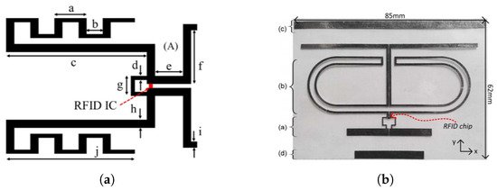 Figure 9. Harmonic RFID tag realization using conventional RFID IC (a) as in [52], [Reproduced with permission from D. Kumar, Harmonic RFID communication using a conventional ultra high frequency (UHF) system; published by IEEE, 2019.] and (b) as in [53]. [Reproduced with permission from G.A. Vera, Third harmonic exploitation in passive UHF RFID; published by IEEE, 2015].The conventional reader’s RF front end needs to be modified to obtain data modulation from the tag at the third harmonic. The new reader configuration was proposed in [52], as shown in Figure 10. The primary challenge in the reader implementation was to prevent leakage of tag transmitted data modulation at the fundamental frequency. Hence, multiple circulators were used to provide enough isolation for the backscattered fundamental frequency. Additionally, the transmitted fundamental frequency path and received third harmonic frequency path were separated using two antennas. The tag modulated third harmonic signal was downconverted at the reader using the second harmonic reference signal. The conventional RFID reader could successfully decode the tag ID from the downconverted fundamental signal.
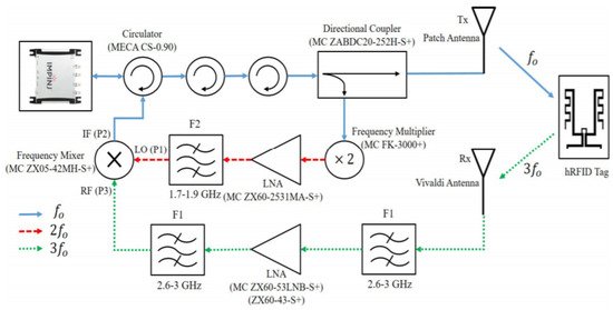 Figure 10. Harmonic RFID reader realization using conventional RFID reader as in [52]. [Reproduced with permission from D. Kumar, Harmonic RFID communication using conventional UHF system; published by IEEE, 2019].
3.3. Antenna Design for Harmonic RFID
2. Drawback of Conventional RFID
2.1. Clutter
2.2. Localization
2.3. Harmonic RFID as a Solution
3. Harmonic RFID
3.1. Chipless Harmonic RFID
3.2. Chip-Based Harmonic RFID
3.2.1. Second Harmonic RFID
3.2.2. Harmonic Exploitation of Conventional RFID
3.3. Antenna Design for Harmonic RFID
One of the major design challenges of harmonic RFID implementation is the dual frequency antenna design. One objective of harmonic RFID is to miniaturize the overall tag area, which requires small antennas, and simultaneously maintain a considerable gain at both the frequencies. Many different antenna designs were proposed in the literature for dual frequency harmonic RFID tag design. In [54], two nested annular slot antennas were used at a 1.2 and 2.4 GHz frequency duplex. As the 2.4 GHz antenna is nested within the 1.2 GHz antenna, the maximum tag area would be the area occupied by the 1.2 GHz antenna. In [42], two half wavelength patch antennas were used at 868 MHz and its second harmonic duplex. As both the patch antennas were kept side-by-side, the total tag area would be at least the summation of both antenna areas. In [29], parallel connected dual band slot antennas resonating at 2.5 and 5 GHz were proposed. In [44], an edge slotted bow-tie antenna was proposed. The bow-tie antenna was designed for second harmonic frequency, and the edge slot provided a secondary resonance for fundamental frequency. Other harmonic tag implementations using conventional RFID ICs required dual antennas resonating at fundamental and third harmonic frequency. In [52], a meandered dipole at fundamental frequency and a standard dipole at third harmonic frequency were implemented. The meandering at the fundamental frequency reduced the overall tag dimension.
References
- Ahuja, S.; Potti, P. An introduction to RFID technology. Commun. Netw. 2010, 2, 183–186.
- Riley, J.; Smith, A.; Reynolds, D.; Edwards, A.; Osborne, J.; Williams, I.; Carreck, N.; Poppy, G. Tracking bees with harmonic radar. Nature 1996, 379, 29.
- Zhang, D.; Yang, L.T.; Chen, M.; Zhao, S.; Guo, M.; Zhang, Y. Real-time locating systems using active RFID for Internet of Things. IEEE Syst. J. 2016, 10, 1226–1235.
- Ruiz-Garcia, L.; Lunadei, L. The role of RFID in agriculture: Applications, limitations and challenges. Comput. Electron. Agric. 2011, 79, 42–50.
- Wamba, S.F.; Anand, A.; Carter, L. A literature review of RFID-enabled healthcare applications and issues. Int. J. Inf. Manag. 2013, 33, 875–891.
- Musa, A.; Dabo, A.A.A. A review of RFID in supply chain management: 2000–2015. Glob. J. Flex. Syst. Manag. 2016, 17, 189–228.
- Liao, J.Y.; Sun, C. Active RFID tag, application system and method thereof. U.S. Patent Application 13/482,734, 20 September 2012.
- Ni, L.M.; Liu, Y.; Lau, Y.C.; Patil, A.P. LANDMARC: Indoor location sensing using active RFID. In Proceedings of the First IEEE International Conference on Pervasive Computing and Communications, 2003. (PerCom 2003), Fort Worth, TX, USA, 26 March 2003; pp. 407–415.
- Lavric, A.; Popa, V. A LoRaWAN: Long range wide area networks study. In Proceedings of the 2017 International Conference on Electromechanical and Power Systems (SIELMEN), Iasi, Romania, 11–13 October 2017; pp. 417–420.
- Nikitin, P.V.; Rao, K. Performance limitations of passive UHF RFID systems. In Proceedings of the 2006 IEEE Antennas and Propagation Society International Symposium, Albuquerque, NM, USA, 9–14 July 2006; pp. 1011–1014.
- Tedjini, S.; Karmakar, N.; Perret, E.; Vena, A.; Koswatta, R.; E-Azim, R. Hold the chips: Chipless technology, an alternative technique for RFID. IEEE Microw. Mag. 2013, 14, 56–65.
- Potyrailo, R.A.; Nagraj, N.; Tang, Z.; Mondello, F.J.; Surman, C.; Morris, W. Battery-free radio frequency identification (RFID) sensors for food quality and safety. J. Agric. Food Chem. 2012, 60, 8535–8543.
- Abad, E.; Zampolli, S.; Marco, S.; Scorzoni, A.; Mazzolai, B.; Juarros, A.; Gómez, D.; Elmi, I.; Cardinali, G.C.; Gómez, J.M.; et al. Flexible tag microlab development: Gas sensors integration in RFID flexible tags for food logistic. Sens. Actuators B Chem. 2007, 127, 2–7.
- Won, D.; Chi, S.; Park, M.W. UAV-RFID Integration for Construction Resource Localization. KSCE J. Civ. Eng. 2020, 24, 1683–1695.
- Yang, P.; Wu, W.; Moniri, M.; Chibelushi, C.C. Efficient object localization using sparsely distributed passive RFID tags. IEEE Trans. Ind. Electron. 2012, 60, 5914–5924.
- Fortin-Simard, D.; Bouchard, K.; Gaboury, S.; Bouchard, B.; Bouzouane, A. Accurate passive RFID localization system for smart homes. In Proceedings of the 2012 IEEE 3rd International Conference on Networked Embedded Systems for Every Application (NESEA), Liverpool, UK, 13–14 December 2012; pp. 1–8.
- Buffi, A.; Motroni, A.; Nepa, P.; Tellini, B.; Cioni, R. A SAR-based measurement method for passive-tag positioning with a flying UHF-RFID reader. IEEE Trans. Instrum. Meas. 2018, 68, 845–853.
- Buffi, A.; Nepa, P.; Cioni, R. SARFID on drone: Drone-based UHF-RFID tag localization. In Proceedings of the 2017 IEEE International Conference on RFID Technology & Application (RFID-TA), Warsaw, Poland, 20–22 September 2017; pp. 40–44.
- Shangguan, L.; Yang, Z.; Liu, A.X.; Zhou, Z.; Liu, Y. STPP: Spatial-temporal phase profiling-based method for relative RFID tag localization. IEEE/ACM Trans. Netw. 2016, 25, 596–609.
- Zhang, J.; Lyu, Y.; Patton, J.; Periaswamy, S.C.; Roppel, T. BFVP: A probabilistic UHF RFID tag localization algorithm using Bayesian filter and a variable power RFID model. IEEE Trans. Ind. Electron. 2018, 65, 8250–8259.
- Luo, Y. Direction Finding for UWB RFID System in Dense Cluttered Environments. Ph.D. Thesis, Nanyang Technological University, Singapore, 2014.
- Gravelle, K.; Landt, J.; Lunsford, P.W. System and method for microwave ranging to a target in presence of clutter and multi-path effects. U.S. Patent 8,786,488, 2014.
- Palazzi, V.; Alimenti, F.; Virili, M.; Mariotti, C.; Orecchini, G.; Mezzanotte, P.; Roselli, L. A novel compact harmonic RFID sensor in paper substrate based on a variable attenuator and nested antennas. In Proceedings of the IEEE MTT-S International Microwave Symposium (IMS), San Francisco, CA, USA, 22–27 May 2016; pp. 1–4.
- Mondal, S.; Chahal, P. A passive harmonic RFID tag and interrogator development. IEEE J. Radio Freq. Identif. 2019, 3, 98–107.
- Ma, Y.; Hui, X.; Kan, E.C. Harmonic-WISP: A passive broadband harmonic RFID platform. In Proceedings of the 2016 IEEE MTT-S International Microwave Symposium (IMS), San Francisco, CA, USA, 22–27 May 2016; pp. 1–4.
- Kim, D.Y.; Yoon, H.G.; Jang, B.J.; Yook, J.G. Effects of reader-to-reader interference on the UHF RFID interrogation range. IEEE Trans. Ind. Electron. 2009, 56, 2337–2346.
- Mondal, S.; Karuppuswami, S.; Kumar, D.; Chahal, P. Scope and application of harmonic RFID for implanted body area network. In Proceedings of the 2020 IEEE International Conference on RFID (RFID), Orlando, FL, USA, 28 September–16 October 2020; pp. 1–8.
- Hui, X.; Kan, E.C. Monitoring vital signs over multiplexed radio by near-field coherent sensing. Nat. Electron. 2018, 1, 74–78.
- Ghazali, M.I.M.; Karuppuswami, S.; Chahal, P. Embedded passive RF tags towards intrinsically locatable buried plastic materials. In Proceedings of the IEEE 66th Electronic Components and Technology Conference (ECTC), Las Vegas, NV, USA, 31 May–3 June 2016; pp. 2575–2580.
- Mondal, S.; Kumar, D.; Ghazali, M.I.; Chahal, P.; Udpa, L.; Deng, Y. Monitoring and localization of buried plastic natural gas pipes using passive RF tags. AIP Conf. Proc. 2018, 1949, 020020.
- Breitbarth, J. Design and Characterization of Low Phase Noise Microwave Circuits. Ph.D. Thesis, University of Colorado at Boulder, Boulder, CO, USA, 2006.
- Wu, H.; Tao, B.; Gong, Z.; Yin, Z.; Ding, H. A fast UHF RFID localization method using unwrapped phase-position model. IEEE Trans. Autom. Sci. Eng. 2019, 16, 1698–1707.
- Ma, H.; Wang, K. Fusion of RSS and phase shift using the Kalman filter for RFID tracking. IEEE Sens. J. 2017, 17, 3551–3558.
- Ni, L.M.; Zhang, D.; Souryal, M.R. RFID-based localization and tracking technologies. IEEE Wirel. Commun. 2011, 18, 45–51.
- Ma, Y.; Kan, E.C. Accurate indoor ranging by broadband harmonic generation in passive NLTL backscatter tags. IEEE Trans. Microw. Theory Tech. 2014, 62, 1249–1261.
- Mondal, S.; Kumar, D.; Chahal, P. A wireless passive pH sensor with clutter rejection scheme. IEEE Sens. J. 2019, 19, 3399–3407.
- Hui, X.; Kan, E.C. Radio ranging with ultrahigh resolution using a harmonic radio-frequency identification system. Nat. Electron. 2019, 2, 125–131.
- Palazzi, V.; Mariotti, C.; Alimenti, F.; Virili, M.; Orecchini, G.; Mezzanotte, P.; Roselli, L. Demonstration of a chipless harmonic tag working as crack sensor for electronic sealing applications. Wirel. Power Transf. 2015, 2, 78.
- Karuppuswami, S.; Ghazali, M.I.M.; Kaur, A.; Chahal, P. Multi-band harmonic RF tags for barcode applications in a cluttered environment. In Proceedings of the 2017 IEEE 67th Electronic Components and Technology Conference (ECTC), Orlando, FL, USA, 30 May–2 June 2017; pp. 1861–1867.
- Alimenti, F.; Roselli, L. Theory of zero-power RFID sensors based on harmonic generation and orthogonally polarized antennas. Prog. Electromagn. Res. 2013, 134, 337–357.
- Dardari, D. Detection and accurate localization of harmonic chipless tags. EURASIP J. Adv. Signal Process. 2015, 2015, 1–13.
- Abdelnour, A.; Lazaro, A.; Villarino, R.; Kaddour, D.; Tedjini, S.; Girbau, D. Passive harmonic RFID system for buried assets localization. Sensors 2018, 18, 3635.
- Mondal, S.; Kumar, D.; Chahal, P. A continuous-mode single-antenna harmonic RFID tag. IEEE Microw. Wirel. Compon. Lett. 2020, 30, 441–444.
- Mondal, S.; Karuppuswami, S.; Kumar, D.; Kaur, A.; Chahal, P. A miniaturized dual band antenna for harmonic RFID tag. In Proceedings of the 51th International Symposium on Microelectronics, Pasadena, CA, USA, 9–11 October 2018.
- Hui, X.; Kan, E.C. Collaborative reader code division multiple access in the harmonic RFID system. IEEE J. Radio Freq. Identif. 2018, 2, 86–92.
- Nikitin, P.V.; Rao, K. Harmonic scattering from passive UHF RFID tags. In Proceedings of the 2009 IEEE Antennas and Propagation Society International Symposium, North Charleston, SC, USA, 1–5 June 2009; pp. 1–4.
- Vera, G.A.; Duroc, Y.; Tedjini, S. RFID test platform: Nonlinear characterization. IEEE Trans. Instrum. Meas. 2014, 63, 2299–2305.
- Vera, G.A.; Duroc, Y.; Tedjini, S. Analysis of harmonics in UHF RFID signals. IEEE Trans. Microw. Theory Tech. 2013, 61, 2481–2490.
- Vera, G.A.; Duroc, Y.; Tedjini, S. Tag-to-reader harmonic link in passive UHF RFID. In Proceedings of the 2014 IEEE MTT-S International Microwave Symposium (IMS2014), Tampa, FL, USA, 1–6 June 2014; pp. 1–4.
- Vera, G.A.; Nawale, S.D.; Duroc, Y.; Tedjini, S. Read range enhancement by harmonic energy harvesting in passive UHF RFID. IEEE Microw. Wirel. Compon. Lett. 2015, 25, 627–629.
- Allane, D.; Vera, G.A.; Duroc, Y.; Touhami, R.; Tedjini, S. Harmonic power harvesting system for passive RFID sensor tags. IEEE Trans. Microw. Theory Tech. 2016, 64, 2347–2356.
- Kumar, D.; Mondal, S.; Karuppuswami, S.; Deng, Y.; Chahal, P. Harmonic RFID communication using conventional UHF system. IEEE J. Radio Freq. Identif. 2019, 3, 227–235.
- Vera, G.A.; Duroc, Y.; Tedjini, S. Third harmonic exploitation in passive UHF RFID. IEEE Trans. Microw. Theory Tech. 2015, 63, 2991–3004.
- Palazzi, V.; Mezzanotte, P.; Roselli, L. Design of a novel antenna system intended for harmonic RFID tags in paper substrate. In Proceedings of the 2015 IEEE Wireless Power Transfer Conference (WPTC), Boulder, CO, USA, 13–15 May 2015; pp. 1–4.