Over the last decade, energy demand from the power grid has increased significantly due to the increasing number of users and the emergence of high-power industries. This has led to a signifi-cant increase in global emissions with conventional energy generation. Therefore, the penetration of renewable energy resources into the power grid has increased significantly. Photovoltaic sys-tems have become the most popular resources as their protentional is enormous, thus, the world-wide installed PV capacity has increased to more than 635 gigawatts (GW), covering approxi-mately 2% of the global electricity demand. Power electronics are an essential part of photovoltaic generation; the drive for efficient power electronic converters is gaining more and more momen-tum. Presently, multilevel inverters (MLI) have become more attractive to researchers compared to two-level inverters due to their abilities to provide lower electromagnetic interference, higher efficiency, and larger DC link voltages.
- multilevel inverter (MLI)
- PV system
- maximum power point tracking
- MPPT
- modified MLC converter
- leakage current suppression
1. Introduction
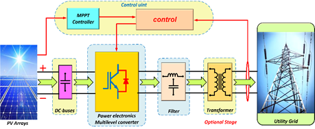
The huge rate of the global energy demand has led to the high consumption of fossil fuels; thus, the environment has been negatively affected owing to the high emission of greenhouse gasses into the atmosphere. Therefore, renewable energy resources have gained attention and development by generating efficient electric power with almost zero pollution [1]. There are various renewable resources, such as solar energy, wind energy, geothermal, etc. [2][3]. Solar radiation contributes largely to the global energy flow. Out of the total amount of solar radiation radiated from the sun, more than 100,000 TW reach the Earth’s surface after reflection and absorption [4]. This amount of free energy has the potential to make solar energy a significant contributor to renewable energy sources [5]. Despite this availability, the global contribution of solar energy to the energy network is still small [6][7]. Significant improvements have indeed been made in the deployment of PV systems over the past three decades, yet certain challenges are still facing solar technologies and, as such, these technologies are yet to compete favorably with the other energy sources, such as fossil fuels, in the energy market. Among these challenges are the high capital cost, intermittency, and modest conversion efficiency of solar technologies [8]. From a technical and scientific perspective, there is an urgent need to develop new technologies that can offer greater conversion efficiencies at a lower production cost as this will improve the entry of solar technologies into the energy market. Several studies have been dedicated to finding solutions to these problems for better reliability, performance, and competitiveness of solar-based energy technologies [9][10][11]. PV cells are used in solar based technologies for the conversion of the solar energy into electrical energy. The components of a system for solar energy conversion include the PV cells, the power converters, and the control unit for the regulation of the power extracted from the PV cells (see Figure 1) [2]. For the efficient harvesting of power from renewable energy sources, various control techniques, power converter topologies, and power tracking methods have been developed [12][13]. Yet, more studies are still focusing on ways of integrating renewable energy sources into the power grid for better efficiency. In this regard, more attention is given to power converters and their controls owing to their vital role in power conversion and output power regulation from these resources. Normally, attention is given to DC/DC converters as the front-end stage of the renewable energy sources’ integration into the DC grid. At this stage, the major requirement is the high efficiency because of the associated variabilities with the output voltage of the renewable energy sources, such as wind and PV energy sources. Therefore, there is a need to ensure the adaptation of the DC/DC front-end stages to such variation so that they can operate maximally. Mostly, the two-level inverters are deployed in small-scale industries and utility applications [14] as they are not suitable for high-power applications due to their production of high voltage stress, low-efficiency operation, and high temperature. Hence, multilevel inverters are mostly used in large-scale high-power grid-connected renewable energy systems [15]. Scholars are focusing more on multilevel inverters due to their low switching losses, high voltage operation capability, low Electro-Magnetic Interference (EMI) output, high efficiency, and good power quality performance (low THD output) due to multiple level output waveform [16].

1. Introduction
The huge rate of the global energy demand has led to the high consumption of fossil fuels; thus, the environment has been negatively affected owing to the high emission of greenhouse gasses into the atmosphere. Therefore, renewable energy resources have gained attention and development by generating efficient electric power with almost zero pollution [1]. There are various renewable resources, such as solar energy, wind energy, geothermal, etc. [2,3]. Solar radiation contributes largely to the global energy flow. Out of the total amount of solar radiation radiated from the sun, more than 100,000 TW reach the Earth’s surface after reflection and absorption [4]. This amount of free energy has the potential to make solar energy a significant contributor to renewable energy sources [5]. Despite this availability, the global contribution of solar energy to the energy network is still small [6,7]. Significant improvements have indeed been made in the deployment of PV systems over the past three decades, yet certain challenges are still facing solar technologies and, as such, these technologies are yet to compete favorably with the other energy sources, such as fossil fuels, in the energy market. Among these challenges are the high capital cost, intermittency, and modest conversion efficiency of solar technologies [8]. From a technical and scientific perspective, there is an urgent need to develop new technologies that can offer greater conversion efficiencies at a lower production cost as this will improve the entry of solar technologies into the energy market. Several studies have been dedicated to finding solutions to these problems for better reliability, performance, and competitiveness of solar-based energy technologies [9–11]. PV cells are used in solar based technologies for the conversion of the solar energy into electrical energy. The components of a system for solar energy conversion include the PV cells, the power converters, and the control unit for the regulation of the power extracted from the PV cells (see Figure 1) [2]. For the efficient harvesting of power from renewable energy sources, various control techniques, power converter topologies, and power tracking methods have been developed [12,13]. Yet, more studies are still focusing on ways of integrating renewable energy sources into the power grid for better efficiency. In this regard, more attention is given to power converters and their controls owing to their vital role in power conversion and output power regulation from these resources. Normally, attention is given to DC/DC converters as the front-end stage of the renewable energy sources’ integration into the DC grid. At this stage, the major requirement is the high efficiency because of the associated variabilities with the output voltage of the renewable energy sources, such as wind and PV energy sources. Therefore, there is a need to ensure the adaptation of the DC/DC front-end stages to such variation so that they can operate maximally. Mostly, the two-level inverters are deployed in small-scale industries and utility applications [14] as they are not suitable for high-power applications due to their production of high voltage stress, low-efficiency operation, and high temperature. Hence, multilevel inverters are mostly used in large-scale high-power grid-connected renewable energy systems [15]. Scholars are focusing more on multilevel inverters due to their low switching losses, high voltage operation capability, low Electro-Magnetic Interference (EMI) output, high efficiency, and good power quality performance (low THD output) due to multiple level output waveform [16].
The first attempt at multilevel converters was made in 1975 [17], starting with the three-level converters [18] and subsequently advanced to several multilevel converters topologies [19][20][21]. However, the MLI is based on the concept of using several DC sources and numerous low-power rated semiconductor switches for the synthesis of a stepped voltage waveform; these are aimed at achieving greater levels of power generation. Various energy sources can be used as multiple-input DC sources, such as batteries, solar PV panels, capacitors, and fuel cells. Then, algorithms are used to control the power switches when combining these multiple DC sources to get a high output voltage [16][22]. There are various industrial applications of MLI topologies, such as in grid-connected renewable energy systems (RES) where it is used as an advanced power converter topology. Currently, the trends in MLIs are mainly focusing on the reduction of the switch count, gate driver circuits, and DC supplies to improve fault tolerance and power quality, thereby making the system cost-efficient for grid-connected RES [23].
Several advance have been witnessed in MPPT controllers in the areas of their accuracy, reliability, efficiency, simplicity, and tracking speed. Normally, the optimal MPPT algorithm exhibits fast speed and less oscillation about the PPP; it goes along with the rapid changes in output power. Several applications of MPPT control techniques are currently available [24]; however, the major application of these controllers is either in tracking the MPP under uniform irradiance or tracking a PV system with MMPP. For any given PV system, the MPP must be unique and must not rely on a complex algorithm to be tracked. Note that there could be some abnormal phenomena in some cases, such as partial shading (PS), which is among the commonest factors with steric effect on the extracted power from PV systems [25]. It is implicated in cases of multipeak points that generate MMPP [26] and global maximum power point (GMPP) [27]. A traditional MPPT algorithm that is under PS normally exhibits low efficiency [28].
Several classifications are available in the literature for the indexing of MPPT controllers [29][30][31]. These classifications are based on different conditions, such as the tracking techniques, modernity, and sensing implementation. Generally, MPPT is classified into the conventional, advanced (soft computing), and hybrid methods. Regarding the conventional methods, they are generally simple but cannot differentiate local peaks from global peaks during PS; hence the causes of low efficiency [28]. Due to their higher efficiency, they require advanced tracking methods to be tracked [32]. Being that the use of the conventional and advanced methods alone is associated with numerous limitations, studies have proposed the hybrid methods as a combination of both methods to overcome these limitations [33]. However, determining the best MPPT method to be used is still an issue. Hence, more studies are still ongoing in the area of MPPT techniques to arrive at a system with better performance in terms of the system cost, the ease of implementation, the tracking efficiency, and the adaptability to different PV systems.
A photovoltaic (PV) system with power electronics and the needed control.
The first attempt at multilevel converters was made in 1975 [17], starting with the three-level converters [18] and subsequently advanced to several multilevel converters topologies [19–21]. However, the MLI is based on the concept of using several DC sources and numerous low-power rated semiconductor switches for the synthesis of a stepped voltage waveform; these are aimed at achieving greater levels of power generation. Various energy sources can be used as multiple-input DC sources, such as batteries, solar PV panels, capacitors, and fuel cells. Then, algorithms are used to control the power switches when combining these multiple DC sources to get a high output voltage [16,22]. There are various industrial applications of MLI topologies, such as in grid-connected renewable energy systems (RES) where it is used as an advanced power converter topology. Currently, the trends in MLIs are mainly focusing on the reduction of the switch count, gate driver circuits, and DC supplies to improve fault tolerance and power quality, thereby making the system cost-efficient for grid-connected RES [23].
Several advance have been witnessed in MPPT controllers in the areas of their accuracy, reliability, efficiency, simplicity, and tracking speed. Normally, the optimal MPPT algorithm exhibits fast speed and less oscillation about the PPP; it goes along with the rapid changes in output power. Several applications of MPPT control techniques are currently available [24]; however, the major application of these controllers is either in tracking the MPP under uniform irradiance or tracking a PV system with MMPP. For any given PV system, the MPP must be unique and must not rely on a complex algorithm to be tracked. Note that there could be some abnormal phenomena in some cases, such as partial shading (PS), which is among the commonest factors with steric effect on the extracted power from PV systems [25]. It is implicated in cases of multipeak points that generate MMPP [26] and global maximum power point (GMPP) [27]. A traditional MPPT algorithm that is under PS normally exhibits low efficiency [28].
Several classifications are available in the literature for the indexing of MPPT controllers [29–31]. These classifications are based on different conditions, such as the tracking techniques, modernity, and sensing implementation. Generally, MPPT is classified into the conventional, advanced (soft computing), and hybrid methods. Regarding the conventional methods, they are generally simple but cannot differentiate local peaks from global peaks during PS; hence the causes of low efficiency [28]. Due to their higher efficiency, they require advanced tracking methods to be tracked [32]. Being that the use of the conventional and advanced methods alone is associated with numerous limitations, studies have proposed the hybrid methods as a combination of both methods to overcome these limitations [33]. However, determining the best MPPT method to be used is still an issue. Hence, more studies are still ongoing in the area of MPPT techniques to arrive at a system with better performance in terms of the system cost, the ease of implementation, the tracking efficiency, and the adaptability to different PV systems.
2. Multilevel Inverters (MLIs)
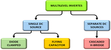
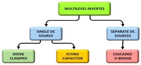
These days, MLIs are being deployed in power systems because of their ability to meet the demand in power quality and power rating, as well as their reduced level of harmonic distortion and electromagnetic interference. There are several advantages of an MLI over the traditional two-level inverters where high switching frequency PWM is used [34,35]. MLIs are currently being considered as an industrial solution for high power quality and dynamic performance demanding systems, spanning through a power range of 1 to 30 MW [36]. Hence, MLIs are ideal for use in high voltage applications because they can generate low THD output voltage waveforms and can generate higher voltages with a limited device rating [37]. The sources of sustainable energy, such as PV cells, fuel cells, and wind can broadly interact with a multilevel converter system [38]. Mostly, the type of control algorithm utilized in the PWM of MLIs determine their operations, efficiency, power ratings, and application [39]. Several studies have proposed various MLI topologies over the last few decades [40–43]. Figure 2 shows the classification of the MLIs into two main groups based on the number of employed DC sources in their topology. Until now, the most commonly used topologies in the industries are the neutral point clamped (NPC) or diode clamped, the flying capacitor (FC), and the cascaded H-bridge (CHB) [44–46].
2. Multilevel Inverters (MLIs)
These days, MLIs are being deployed in power systems because of their ability to meet the demand in power quality and power rating, as well as their reduced level of harmonic distortion and electromagnetic interference. There are several advantages of an MLI over the traditional two-level inverters where high switching frequency PWM is used [34][35]. MLIs are currently being considered as an industrial solution for high power quality and dynamic performance demanding systems, spanning through a power range of 1 to 30 MW [36]. Hence, MLIs are ideal for use in high voltage applications because they can generate low THD output voltage waveforms and can generate higher voltages with a limited device rating [37]. The sources of sustainable energy, such as PV cells, fuel cells, and wind can broadly interact with a multilevel converter system [38]. Mostly, the type of control algorithm utilized in the PWM of MLIs determine their operations, efficiency, power ratings, and application [39]. Several studies have proposed various MLI topologies over the last few decades [40][41][42][43]. Figure 2 shows the classification of the MLIs into two main groups based on the number of employed DC sources in their topology. Until now, the most commonly used topologies in the industries are the neutral point clamped (NPC) or diode clamped, the flying capacitor (FC), and the cascaded H-bridge (CHB) [44][45][46].
2.1. Cascaded H-Bridges MLI
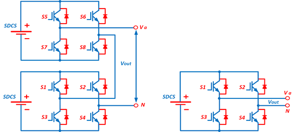
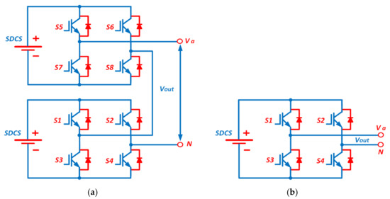
The CHB-MLIs are produced from the serial connection of numerous single-phase H-bridge inverters with separate DC sources (SDCS). Each H-bridge consists of four unidirectional power switches and one DC source as shown in Figure 3 [22]. Each inverter level is programmed to produce three voltage outputs (+Vdc, 0, and −Vdc) via the connection of the DC source to the AC output; the desired output is achieved by connecting the four switches (S1–S4) in different manners. Switching the S1 and S4 switches to the ON position generates the +Vdc output, but when S2 and S3 are in the ON position, −Vdc output is produced. To produce the 0 output voltage, either S1 and S2 or S3 and S4 must be in the ON position. A serial connection of the AC outputs of the full-bridge inverter is made in such a way that the generated voltage waveform will represent the sum of the outputs of all the inverters. In a cascade inverter, m = 2s + 1
Multilevel inverters (MLIs) and their classification.
2.1. Cascaded H-Bridges MLI
The CHB-MLIs are produced from the serial connection of numerous single-phase H-bridge inverters with separate DC sources (SDCS). Each H-bridge consists of four unidirectional power switches and one DC source as shown in Figure 3 [22]. Each inverter level is programmed to produce three voltage outputs (+Vdc, 0, and −Vdc) via the connection of the DC source to the AC output; the desired output is achieved by connecting the four switches (S1–S4) in different manners. Switching the S1 and S4 switches to the ON position generates the +Vdc output, but when S2 and S3 are in the ON position, −Vdc output is produced. To produce the 0 output voltage, either S1 and S2 or S3 and S4 must be in the ON position. A serial connection of the AC outputs of the full-bridge inverter is made in such a way that the generated voltage waveform will represent the sum of the outputs of all the inverters. In a cascade inverter, is used to represent the number of output phase voltage levels, with s being the number of different DC sources [47]. This topology requires a smaller number of components when compared to DCMLI and FCMLI because it does not have clamping diodes and clamping capacitors. In addition to that, it is free from the voltage balancing problem because it does not contain DC link capacitors [23,48]. On the other hand, the multiple DC sources can be replaced either by separate renewable energy sources with separate converters or by single renewable energy sources with multioutput converters where the voltage balancing is the major concern.
Proposals have been made for the use of multilevel cascaded inverters in applications for static var generation, as well as their usage as an interface with RES [49]; they have also been proposed for use in battery-powered applications. A cascade inverter can also be used for static var compensation via direct connection in series with the electric system. They are suitable for the hooking of RES to the AC grid as they need separate DC sources when used in fuel cells and photovoltaics [50]. They have also been proposed to be used in electric vehicles as the main traction drive because in such applications several batteries or ultracapacitors serve as SDCSs [51]. The structure of this topology is flexible and can be used in different number of inverter levels. The generation of the different output voltages is achievable via the application of different ratios of the DC sources and reducing the inner voltage levels-related switching redundancy. Transformer-dependent CHBMLIs are developed to reduce the need for independent DC sources; it is like the CHBMLI structure but differs by the serial connection of the output voltage of the isolation transformer [52].
|
|
|
| FC-MLI [22][35][41][57][59][62][63] |
|
|
| CHB-MLI [22][23][59][64][65][66][67] |
|
|
 |
|
|
(a) |
(b) |
is used to represent the number of output phase voltage levels, with s being the number of different DC sources [47]. This topology requires a smaller number of components when compared to DCMLI and FCMLI because it does not have clamping diodes and clamping capacitors. In addition to that, it is free from the voltage balancing problem because it does not contain DC link capacitors [23][48]. On the other hand, the multiple DC sources can be replaced either by separate renewable energy sources with separate converters or by single renewable energy sources with multioutput converters where the voltage balancing is the major concern.
(
) Five-level CHBMLI topology, (
Proposals have been made for the use of multilevel cascaded inverters in applications for static var generation, as well as their usage as an interface with RES [49]; they have also been proposed for use in battery-powered applications. A cascade inverter can also be used for static var compensation via direct connection in series with the electric system. They are suitable for the hooking of RES to the AC grid as they need separate DC sources when used in fuel cells and photovoltaics [50]. They have also been proposed to be used in electric vehicles as the main traction drive because in such applications several batteries or ultracapacitors serve as SDCSs [51]. The structure of this topology is flexible and can be used in different number of inverter levels. The generation of the different output voltages is achievable via the application of different ratios of the DC sources and reducing the inner voltage levels-related switching redundancy. Transformer-dependent CHBMLIs are developed to reduce the need for independent DC sources; it is like the CHBMLI structure but differs by the serial connection of the output voltage of the isolation transformer [52].
) three-level CHBMLI topology.
2.2. Flying Capacitor MLI
There are close similarities in the topologies of the FCMLI and DCMLI just that the FCMLI relies on the use of floating capacitors rather than clamping diodes. For the FCMLI, the magnitude of the voltage steps in the output waveform is a direct function of the voltage variation occurring in the adjacent capacitors [53]. The FCMLI topology for the ‘m’ level inverter is comprised of DC link capacitors count. Figure 4 is a schematic of the 3-level FCMLI topology which contains four unidirectional power switches and a flying capacitor, in addition to a DC supply with two capacitors for obtaining voltage levels (Vdc/2, 0, −Vdc/2). Switches S1 and S2 must be in the ON position to generate the positive polarity output voltage while S3 and S4 are switched ON for the negative polarity output voltage. Switches S1 and S3 or S2 and S4 are turned on to generate the 0 level output voltage. In the FCMLI, the voltage synthesis is more flexible compared to that of a DCMLI. When there are more than five levels, the problem of voltage balancing can be addressed by making a proper selection of the switching combination [34]. One major advantage of this topology is that the reactive and active power can be controlled [53] while its major drawback is in the use of several capacitors, which makes the system expensive and difficult to assemble. Furthermore, the switching frequency losses in such arrangements are high in real power transmission [54].
2.2. Flying Capacitor MLI
There are close similarities in the topologies of the FCMLI and DCMLI just that the FCMLI relies on the use of floating capacitors rather than clamping diodes. For the FCMLI, the magnitude of the voltage steps in the output waveform is a direct function of the voltage variation occurring in the adjacent capacitors [53]. The FCMLI topology for the ‘m’ level inverter is comprised of ‘m−1’
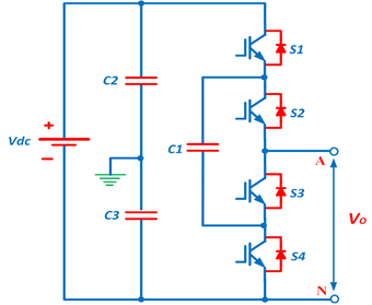
DC link capacitors count. Figure 4 is a schematic of the 3-level FCMLI topology which contains four unidirectional power switches and a flying capacitor, in addition to a DC supply with two capacitors for obtaining voltage levels (Vdc/2, 0, −Vdc/2). Switches S1 and S2 must be in the ON position to generate the positive polarity output voltage while S3 and S4 are switched ON for the negative polarity output voltage. Switches S1 and S3 or S2 and S4 are turned on to generate the 0 level output voltage. In the FCMLI, the voltage synthesis is more flexible compared to that of a DCMLI. When there are more than five levels, the problem of voltage balancing can be addressed by making a proper selection of the switching combination [34]. One major advantage of this topology is that the reactive and active power can be controlled [53] while its major drawback is in the use of several capacitors, which makes the system expensive and difficult to assemble. Furthermore, the switching frequency losses in such arrangements are high in real power transmission [54].
Three-level flying capacitor MLI topology.
2.3. Diode Clamped MLI
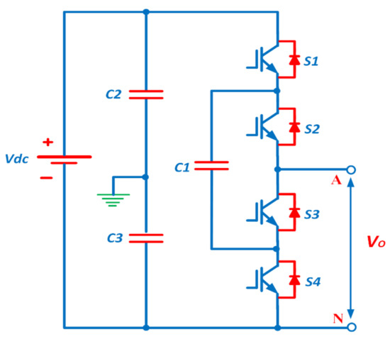
This type of inverter, also called a neutral point clamped inverter (NPC), was invented in 1981 by Nabae et al. [18]. Figure 5 depicts the DCMLI topology, which is used to generate an output voltage with three levels. The configuration for this topology contains four unidirectional power switches, two diodes, and two capacitors. The clamping diodes are connected in series to share the blocking voltage. In this topology, the output voltage is of three levels, which are Vdc/2, 0, and −Vdc/2; Vdc/2 is generated by keeping S1 and S2 switches ON while S3 and S4 are switched to ON to generate −Vdc/2. Switches S2 and S3 are turned on to produce the 0 level voltage. During the passage of the equivalent voltage through the DC link capacitors, it is expected that each active switching device has voltage stress that is clamped to the voltage of each capacitor through diode clamping [54]. In a real application, the blocking voltage is shared by serially connecting the clamping diodes. Then, only a voltage level of dc is required to be blocked by each active device. For reverse voltage blocking, the voltage ratings of the clamping diodes must vary. If operating the DCMLI under the PWM technique, the major issue with the design in high voltage applications is the diode reverse recovery of these clamping diodes [55].
The DCMLI, in comparison to the other multilevel converter topologies, has a greater industrial application due to its high-power delivery capability, simplicity, and efficiency. It has found application in Static VAR Compensators (SVC), high voltage system interconnections [55,56], and variable speed motor drives. The need for a capacitance is annulled in the DCMLI converter as the components share a common DC bus. Hence, it can be used in high voltage back-to-back interconnection, adjustable speed drives, and other back-to-back topologies. However, the problems of this converter include difficulty in single inverter real power flow due to discharging or overcharging of the DC level without adequate control [57], as well as the issue of balancing and stabilizing the capacitor DC voltage in the DC link [41].
2.3. Diode Clamped MLI
This type of inverter, also called a neutral point clamped inverter (NPC), was invented in 1981 by Nabae et al. [18]. Figure 5 depicts the DCMLI topology, which is used to generate an output voltage with three levels. The configuration for this topology contains four unidirectional power switches, two diodes, and two capacitors. The clamping diodes are connected in series to share the blocking voltage. In this topology, the output voltage is of three levels, which are Vdc/2, 0, and −Vdc/2; Vdc/2 is generated by keeping S1 and S2 switches ON while S3 and S4 are switched to ON to generate −Vdc/2. Switches S2 and S3 are turned on to produce the 0 level voltage. During the passage of the equivalent voltage through the DC link capacitors, it is expected that each active switching device has voltage stress that is clamped to the voltage of each capacitor through diode clamping [54]. In a real application, the blocking voltage is shared by serially connecting the clamping diodes. Then, only a voltage level of V /(m−1)
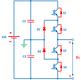
dc is required to be blocked by each active device. For reverse voltage blocking, the voltage ratings of the clamping diodes must vary. If operating the DCMLI under the PWM technique, the major issue with the design in high voltage applications is the diode reverse recovery of these clamping diodes [55].
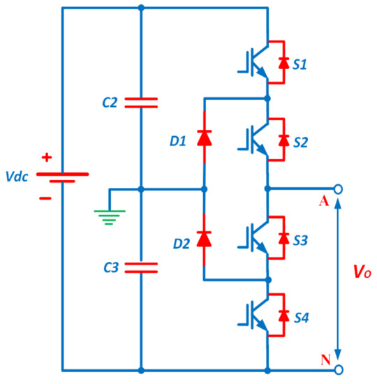
The DCMLI, in comparison to the other multilevel converter topologies, has a greater industrial application due to its high-power delivery capability, simplicity, and efficiency. It has found application in Static VAR Compensators (SVC), high voltage system interconnections [55][56], and variable speed motor drives. The need for a capacitance is annulled in the DCMLI converter as the components share a common DC bus. Hence, it can be used in high voltage back-to-back interconnection, adjustable speed drives, and other back-to-back topologies. However, the problems of this converter include difficulty in single inverter real power flow due to discharging or overcharging of the DC level without adequate control [57], as well as the issue of balancing and stabilizing the capacitor DC voltage in the DC link [41].
Three-level diode-clamped MLI topology.
2.4. Comparison between CHB-MLI, FC-MLI, and DC-MLI Topologies
In this section, a comparison between the three main MLI topologies, called the classical topologies, was made in terms of the advantages and disadvantages, as illustrated in Table 1.
2.4. Comparison between CHB-MLI, FC-MLI, and DC-MLI Topologies
In this section, a comparison between the three main MLI topologies, called the classical topologies, was made in terms of the advantages and disadvantages, as illustrated in Table 1.
| Types of MLI | Advantages | Disadvantages |
|---|---|---|
| DC-MLI [18][35][41][55][57][58][59][60][61] |
| |
|
|
Advantages and disadvantages of the classical topologies (DC-MLI, FC-MLI, and CHB-MLI).
|
Types of MLI |
Advantages |
Disadvantages |
|
DC-MLI [18,35,41,55,57–61] |
· A good option for industrial applications. · Exhibits high fundamental frequency switching efficiency. · Can precharge the capacitors as a group. · Control method is simple. · Reduces the number of required DC sources. · Appropriate for fault-tolerant application. · The use of neutral clamping switches can solve the issue of voltage balancing and uneven loss sharing between the switching devices in neutral point clamped (NPC) converters. |
· The complexity of voltage balancing circuit. · The unequal share of losses between inner and outer switches. · Increased number of clamping diode as the level increased. |
|
FC-MLI [22,35,41,57,59,62,63] |
· Reduces the number of required DC sources. · Phase redundancies are available for balancing the voltage levels of the capacitors. · Appropriate for fault-tolerant application. · Real and reactive power flow can be controlled · No need for filters to reduce harmonics. |
· The complexity of voltage balancing circuit. · Requires numerous capacitors for high levels. · High losses and switching frequency for real power transmission. · High installation cost. |
|
CHB-MLI [22,23,59,64–67] |
· Modular and simple structure. · Easy to extend to higher levels. · Requires only unidirectional switches. · Appropriate for fault-tolerant application. · Potential of electric shock is reduced due to the separate DC sources. · Asymmetric source configuration can be employed. · Can be implemented as a single DC source configuration. |
· Less number of output voltage levels. · Requires more number of gate driver circuits. · Requires several DC sources to increase the output voltage. · Limited to certain applications where separate DC sources are available. · Switches have to bear blocking voltage equal to the input voltage value. · Loss of modularity (asymmetric source configuration). · Implement cost is high (asymmetric source configuration). · Switches are differently voltage rated (asymmetric source configuration). |