Ceramics and ceramic-reinforced metal matrix composites (CMMCs) demonstrate high wear resistance, excellent chemical inertness, and exceptional properties at elevated temperatures. These characteristics are suitable for their utilization in biomedical, aerospace, electronics, and other high-end engineering industries. The aforementioned performances make them difficult to fabricate via conventional manufacturing methods, requiring high costs and energy consumption. To overcome these issues, laser additive manufacturing (LAM) techniques, with high-power laser beams, were developed and extensively employed for processing ceramics and ceramic-reinforced CMMCs-based coatings. In respect to other LAM processes, laser melting deposition (LMD) excels in several aspects, such as high coating efficiency and lower labor cost. Nevertheless, difficulties such as poor bonding between coating and substrate, cracking, and reduced toughness are still encountered in some LMD coatings.
- 3D printing
- laser melting deposition
- ceramic-based coatings
- ceramic-reinforced metal matrix composite-based coatings
- properties of coatings
1. Introduction
Ceramics and ceramic-reinforced metal matrix composites (CMMCs)-based coatings exhibit enhanced properties, including wear resistance, modulus and strength, chemical inertness, and properties at high operating temperatures [1][2][3][4][1,2,3,4]. Owing to these benefits, these coatings have been widely used in extreme working conditions, such as high load, wear, and temperature [5][6][5,6]. There are several commercialized applications of the aforementioned coatings in biomedical [7][8][7,8], aerospace [9], electronic [10], and other high-end engineering [11][12][13][11,12,13].
Because of the high hardness and elevated melting point, ceramics and CMMCs-based coatings are too difficult to process by conventional manufacturing processes [14][15][16][17][14,15,16,17]. A study [15] was conducted on diamond grinding of hot pressed Si3N4 and Al2O3, slip casted ZrO2, and sintered SiC ceramics. It was found that hot-pressing, slip casting and sintering processes resulted in high cost and energy utilizations, while microcracks were observed due to grinding process. Recently, additive manufacturing (AM) has gained great attention and is still under continuous investigations in the case of ceramics and ceramic-reinforced MMCs-based coatings [18]. AM, as defined by the American Society for Testing and Materials (ASTM), is “a technique, opposite to the subtractive manufacturing processes, of joining materials to make a 3D object using a CAD model, generally layer upon layer” [19]. In comparison to conventional coating processes, AM can produce coatings with reduced lead time, exemption from assembly or molds preparations, and less energy consumption [20][21][22][20,21,22].
1.1. Various Additive Manufacturing Processes
Based on the literature survey, AM process can be classified into two methods: (a) indirect and (b) direct. Indirect AM methods include fused deposition modeling [23], stereolithography [24], direct inkjet printing [25][26][25,26], layer-wise slurry deposition [27][28][27,28], and laminated object manufacturing process [29]. Generally, in indirect AM process, the coatings are produced using binding materials. Subsequently, the printed coating is sintered to eliminate the binding materials. Direct AM methods contain selective laser sintering [30][31][30,31], selective laser melting [32][33][32,33], and laser-melting deposition process [34][35][34,35]. The later basically integrates the forming and densification procedures, producing a coating without the post-sintering requirement. Consequently, the coatings by direct AM method exhibit relatively higher density and purity, better mechanical characteristics, and require less time and energy, as compared to indirect AM method [36][37][36,37]. Furthermore, in direct AM methods, a laser beam is used as a heating source having high directionality and energy intensity, thus delivering a large amount of energy to the target (substrate) [38]. The direct AM method is also known as laser additive manufacturing (LAM) processes.
1.2. Laser Additive Manufacturing (LAM) Processes: Selective Laser Sintering and Melting
A schematic illustration of selective laser sintering (SLS) and melting (SLM) is presented in Figure 1. The only difference between SLS and SLM is that SLS involves the partial melting of powders, while the complete melting of powder debits is involved in SLM process. As a consequence, the deposited coatings via SLS yield low density and poor mechanical properties. On the other hand, SLM can produce near fully dense coatings with better mechanical properties [39]. Figure 1 shows that, at first, the substrate is moved downward by a mounted piston, leaving one layer-thickness space. Following on, a powder distributor spreads a specific amount of powder, evenly. The laser beam, which is controlled and directed by XY scanning mirrors and an f-θ lens, melts the powder and forms the first layer. Afterwards, the substrate moves downward to another layer thickness for the formation of the next layer. The designed component is fabricated by repeating the aforementioned steps [40].
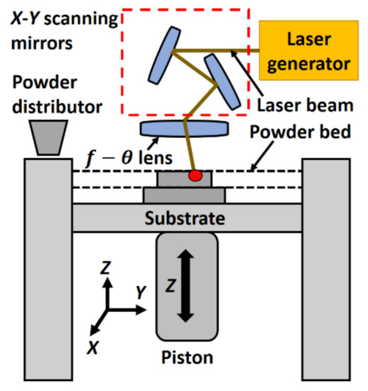
Figure 1. Schematic diagram of selective laser sintering and melting.
1.3. Laser Additive Manufacturing (LAM) Process: Laser Melting Deposition (LMD)
Figure 2 presents the schematic of the LMD process. Primarily, the substrate is melted by heat from laser radiation, generating a melt pool that captures and melts the powder provided by a powder nozzle. The powder particles are carried and mixed by a jet of gases, such as argon and helium. As the laser source departs, the molten pool solidifies as a result of heat dissipation. The deposition head moves along the designated path, provided by a 3D CAD file, resulting in a layer deposition on the substrate. Afterwards, the deposition head moves upward by one-layer thickness for the deposition of the next coating. The previously deposited layer is partially melted, serving as a substrate for the formation of the next one. The aforementioned steps are repeated several times, until the designed 3D component is built layer after layer [37]. The LMD process mainly comprises laser engineered net shaping (LENS) and direct metal deposition (DMD) processes.
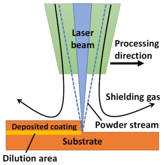
Figure 2.
Schematic of laser melting deposition (LMD) process.
Among the developed LAM techniques, LMD has been widely used efficiently for the coating of a surface with a layer of ceramics and/or CMMCs. This process is usually carried out on the surfaces of bulk (new/worn-out) materials with the emphasis on enhancing the surface characteristics or obtaining the desired biological, frictional, or chemical characteristics for a given material [18]. Equipped with high energy density laser beams, LMD setups have demonstrated their capabilities to process materials with high hardness and elevated melting points. In comparison to SLS and SLM processes, LMD procedure presents the advantages of low effort intensity and high fabrication efficiency [41][42][43][41,42,43]. Besides the benefits mentioned above, difficulties such as poor bonding, cracking, or lower toughness exist, however, in ceramics and CMMCs-based coatings [44]. The solutions to these issues require major dedication from scientists and researchers. The possible solutions include process optimization, adding a buffer layer and/or functionally gradient composite (FGC) layers, integrating the ultrasonic vibration, pre/post-substrate heating, adding additive materials, and tailoring the novel microstructure [45][46][47][48][49][45,46,47,48,49].
2. Coatings by LMD
There are two major types of near-net shape LMD coatings identified through the literature survey: (a) ceramics and (b) CMMCs-based coatings.
2.1. Ceramics-Based Coatings: Compositions and Properties
The LMD process has the capability to process ceramics having high hardness and a melting point up to 3000 °C. The following coatings have been identified based on the literature survey.
2.1.1. Alumina-Based Coatings
Alumina (Al2O3) is a white or nearly colorless crystalline substance that is used as a preliminary material for the smelting of aluminum metal. It also serves as a raw material for a broad range of advanced ceramic products and as an active agent in chemical processing [50]. The properties of pure alumina are given in Table 1.
Table 1. Properties of alumina [51].
| Composition | Al | 2 | O | 3 | + MgO | |||||
| Properties (Units) | Porosity (%) | <0.10 | ||||||||
| Purity (%) | 99.9 | |||||||||
| Density (g/cm | 3 | ) | 3.0–4.0 | |||||||
| Young’s modulus (GPa) | 350–380 | |||||||||
| Bending strength (MPa) | 7500 | |||||||||
| Poisson’s ratio | 0.23 | |||||||||
| Hardness (HV 0.1) | 2100–2200 | |||||||||
| Coefficient of thermal expansion (×10 | −6 | /K) | 8.0 | |||||||
Various studies have been carried on the coatings of Al2O3. Recently, fully dense bulk Al2O3 structures were deposited via LMD with a 0.5 kW continuous wave Nd: YAG laser on a 3-mm-thick Al2O3 substrate. It was found that the deposited layers show anisotropy in mechanical properties with a high compressive strength perpendicular to the build direction and columnar grains parallel to the deposition direction. Heat treatment did not change the strength and anisotropy, but the grain size increased from 6 to 200 mm. In addition, the hardness increased from 1550 to 1700 HV [35]. In another study, the effects of input deposition variables, including laser power, deposition head scanning speed, and powder feeding rate on deposition quality were analyzed. The laser power improves the length, width, surface roughness, flatness, powder efficiency, and microhardness of the deposited clad, but an inverse relation has been found between laser power and clad height. An increment in laser scanning speed causes a decrease in length, width, height, powder efficiency, surface roughness, and microhardness, but with a positive impact on flatness. However, a random behavior was found with regard to the powder feeding rate [36].
Pure alumina coatings (black/white) were deposited by LENS on Ti6Al4V substrates [52]. The coatings showed many evenly distributed surface cracks. The formation process effects both the volatility degree of oxide impurities in the particles, as well as the chemical elements and phase compositions in the samples. The development of the second phase is a major source for obtaining the black coatings and promoting the formation and propagation of surface cracks in the coating. An analytical model was developed to avoid a huge number of experiments for finding the optimal deposition parameters. The analytical formulae were presented, which could reveal the relationship between the operating parameters and physical properties of the Al2O3 parts to be fabricated [53].
The effects of laser scanning speed on the typical defects, microstructure, and mechanical properties of prepared samples were investigated, resulting in optimized process parameters [54]. The results showed that the laser scanning speed has a substantial influence on the macroscopic defects, microstructure characteristics, and mechanical properties. Slow laser scanning speed resulted in longer retaining time of the molten pool, which was beneficial to pore suppression. A fast scanning reduced the temperature gradient at the bottom of the melt pool to achieve crack-free depositions. The fracture toughness of the coatings gradually increased as the scanning speed increased, while a parabolic behavior was observed in the case of flexural strength. The optimal deposition was achieved at a scanning speed of 300−500 mm/m. The deposited material had up to 98% densification at this scanning speed, resulting in 1640 HV hardness, 3.75 MPa·m1/2 fracture toughness, and 212 MPa flexural strength. FigureFigure 4 3 shows the SEM images of the typical microstructure of alumina + aluminum titanate composite ceramics. All samples contain dark and bright phases. The dark α-Al2O3 phase accounts for the main volume fraction, while the Al6Ti2O13 one is distributed in a network. For low and medium scanning speeds (Figure 3Figure 4a–d), the Al2O3 grains’ length along the deposition height is slightly longer than that perpendicular to the deposition direction. When using high-scanning speeds (FigurFigure 4e 3e,f), the preferential growth of Al2O3 grains along the deposition direction is significantly weakened.
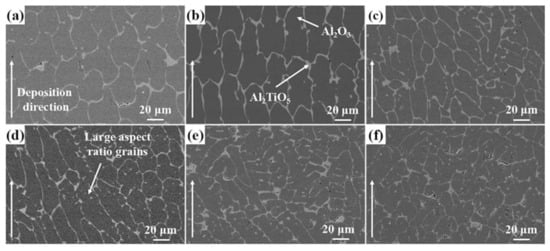
Figure 34. Microstructure of alumina + aluminum titanate composite ceramics for a scanning speed of 50 (a), 100 (b), 300 (c), 500 (d), 700 (e), and 900 (f) mm/min [54]; with permission from Elsevier.
2.1.2. Hydroxyapatite-Based Coatings
Hydroxyapatite (HAP) materials have gained interest from researchers because of outstanding biocompatibility, osteoconductive characteristics, and similarity to the inorganic component of human bones. They are widely used in biomedical materials [55][56][55,56], bone tissue engineering scaffolds [57], bioactive coatings [58], soft tissue repairs [59][60][61][62][59,60,61,62], drug delivery systems [63][64][65][66][67][68][63,64,65,66,67,68], and column chromatography for rapid fractionation of biomolecules [69][70][69,70]. HAP materials are also probable aspirants for usage in cell targeting, fluorescence labeling, and imaging and diagnosis materials [71][72][71,72]. The properties of HAP are given in Table 2 [73].
Table 2. Properties of hydroxyapatite [73].
| Formula | Ca | 5 | (PO | 4 | ) | 3 | (OH) |
| Composition | Ca + P | ||||||
| Theoretical density | 3.156 (g/cm | 3 | ) | ||||
| Hardness | 500–800 (HV) | ||||||
| Tensile strength | 40–100 (MPa) | ||||||
| Bend strength | 20–80 (MPa) | ||||||
| Compressive strength | 100–900 (MPa) | ||||||
| Fracture toughness | 1.0 (MPam | 1/2 | ) | ||||
| Young’s modulus | 70–120 (GPa) |
HAP was coated on Ti6Al4V using the LMD process [74]. One can obtain coatings with decent metallurgical bonding and slight dilution. The microstructural and mechanical properties, chemical composition, and bio-activities of the produced coatings were studied. The results showed that the laser power has a great impact on microstructure evolution, mechanical characteristics, and retainment of HAP coatings. Laser power equivalent to 750 W yielded no dilution. The microhardness results (1100 HV) inferred a strong intermetallic–ceramic bonding, which means that the coating at 750 W can last a long time during service. The hardness increases from the top to the bottom of the coatings or near to the heat-affected zone. The soak tests revealed that the surface of the coating had un-melted HAP crystals. FigureFigure 5 4 shows the SEM images of the HAP coatings.
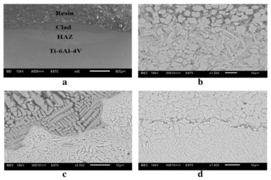
Figure 45. SEM images of hydroxyapatite (HAP) coatings after etching at 750 W (a), cross-section (b), cross-section clad and heat-affected zone (c), and cross-section heat-affected zone and Ti6Al4V substrate (d) [74]; published under open-access license by Elsevier.
HAP + yttria-stabilized zirconia (YZS) composite coatings were cladded by LMD on a titanium alloy substrate. The effects of zirconia on the microstructure, mechanical properties, and the formation of tricalcium phosphate from the HAP + YSZ composite coatings were evaluated. The experimental results showed that adding YSZ in coatings was favorable to the composition and stability of HAP, which leads to the improvement of adhesion strength, microhardness, and micro-toughness [75]. Two types of porous HAP coatings were produced and tested with regard to their reprecipitation in a semi dynamic simulated physiological solution. Coatings having higher porosity were produced using a 355 nm laser wavelength, exhibited substantial reprecipitation more quickly than those deposited by a 266 nm laser wavelength. The dissolution of the non-HAP phases played a key role in the reprecipitation of HAP-like material. The Ca/P ratio of the coatings became nearer to the hypothetical value of HAP. The reprecipitation resulted in a very condensed morphology, suggesting a mechanically robust structure after reprecipitation. Despite dissolution and reprecipitation, the coatings showed sufficient stability in the solution and no significant loss of the coatings were found. Such results prove that HAP coatings can be used in clinical applications [76].
HAP coatings were deposited onto mild steel substrates under several laser power and stand-off distance conditions. The results indicated that microhardness and deposition efficiency increased with increasing power and stand-off distance. Porosity and surface roughness decreased as the Ca/P ratio steadily decreased [77], as shown in Figure 5Figure 6.
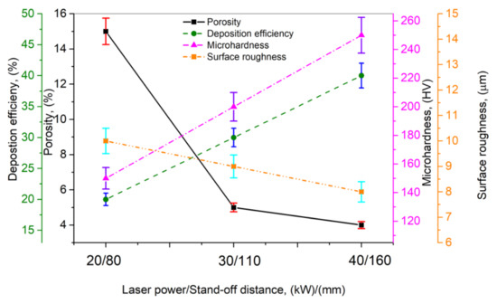
Figure 56. Effect of laser power/standoff distance on porosity, deposition efficiency, microhardness, and surface roughness; based on the data given in Reprinted from permission from [77]. Copyright year Copyright owner’s name [77].
