Solid oxide fuel cells (SOFCs) have been considered as promising candidates to tackle the need for sustainable and efficient energy conversion devices. However, the current operating temperature of SOFCs poses critical challenges relating to the costs of fabrication and materials selection. To overcome these issues, many attempts have been made by the SOFC research and manufacturing communities for lowering the operating temperature to intermediate ranges (600–800 °C) and even lower temperatures (below 600 °C). Despite the interesting success and technical advantages obtained with the low-temperature SOFC, on the other hand, the cell operation at low temperature could noticeably increase the electrolyte ohmic loss and the polarization losses of the electrode that cause a decrease in the overall cell performance and energy conversion efficiency. In addition, the electrolyte ionic conductivity exponentially decreases with a decrease in operating temperature based on the Arrhenius conduction equation for semiconductors.
- low-temperature solid oxide fuel cell
- low-temperature electrolyte
- electrochemical performance
1. Introduction
Deploying more efficient and robust power conversion devices to supply affordable energy with reduced CO2 emission becomes one of the biggest global challenges in this century. Today, more than 70% of the global energy demand for power generation, transportation, and industrial heating comes from fossil fuels extracted from deep within the Earth’s crust. However, harnessing energy from fossil fuels is associated with two major drawbacks: first, due to the scarcity and exhaustible nature of these fuels, they may fail to satisfy the increasing rate of energy demand in the close future; and second, those fuels eventually lead to an increase in the atmospheric concentrations of greenhouse gases (GHGs) which consequently cause a noticeable change in the climate patterns with a contribution to acid rains, water pollution, air pollution, global warming, etc. [1][2][3][4][5][6][1,2,3,4,5,6]. Thus, a comprehensive and urgent solution shall be developed to tackle both the energy and environmental challenges based on the renewable energy sources (such as solar, wind, hydroelectric power, etc.), along with the application of more sustainable energy conversion devices. Nowadays, there is a growing interest in developing fuel cells for both portable and stationary power applications because of their high efficiency, environmental-friendly operation, and fuel flexibility [7][8][9][10][7,8,9,10]. A fuel cell is an electrochemical device that can directly convert the chemical energy of fuels into electricity through a more reversible operation. The first fuel cell, so-called "the gas voltaic battery", was invented by Sir William Grove in 1839, which could generate electricity by combining hydrogen and oxygen gases [7][11][7,11]. Offering a relatively higher efficiency (65–85%) and fewer emissions compared to the internal-combustion engines (Carnot cycle, with an efficiency below 45% [12]), fuel cell technology is considered as one of the most promising candidates for replacing the conventional power generation systems [7][8][9][10][7,8,9,10].
Fuel cells are structurally comprised of an electrolyte layer sandwiched between a couple of porous electrodes. The electrolyte layer has an essential role, as the heart of fuel cell, for indicating the cell operating temperature range, the type of the electrochemical reactions taking place at the electrodes, and the type of catalytic constituents of the electrodes. Thus, fuel cells are classified based on the type of their electrolyte material into various categories such as alkaline fuel cell (AFC) [13], direct methanol fuel cell (DMFC) [14], molten carbonate fuel cell (MCFC) [15], proton exchange membrane fuel cell (PEMFC) [16], phosphoric acid fuel cell (PAFC) [13], solid oxide fuel cell (SOFC) [17], and so on. Among the different types of fuel cells, solid oxide fuel cells have attracted great interests because of their unique properties such as offering comparably a higher efficiency, extensive fuel flexibility, more durability, and relatively lower cost of fabrication because of their capability to operate with non-precious metals [8][14][18][19][20][21][22][8,14,18,19,20,21,22]. SOFCs have a wide range of applications including combined heat and power (CHP) systems, stationary and portable power plants, hybrid vehicles, distributed power sources, etc. [1][20][23][24][1,20,23,24]. Despite the numerous advantages of SOFC, however, their relatively slower start-up, thermochemical instability of the cell individual layers, and the high-temperature range required for exhibiting adequate ionic activity have been addressed to be their major drawbacks [3][8][24][25][26][3,8,24,25,26].
2. Advances in Low-Temperature SOFC Electrolytes (L-T SOFC)
The electrolyte layer is the heart of a SOFC that determines the operating temperature of the cell with a strong impact on its electrochemical performance [27][121]. Currently, YSZ is the state-of-the-art material used for the fabrication of SOFCs. However, due to the high activation energy (∼1 eV) of YSZ, this classical SOFC electrolyte provides the acceptable range of ionic conductivity (1–10 S/cm) only at a high-temperature range (800–1000 °C) [28][29][107,122]. The high operating temperature could be advantageous for developing large-scale power plants, especially the systems based on the combined heat and power (CHP) cycles. However, the current technical challenges associated with operating at high temperatures (such as higher degradation rates and slower start-up and shutdown cycles, etc.), have limited the application of SOFCs for developing portable and auxiliary power systems. Lowering the operating temperature, on the other hand, can significantly reduce the degradation processes associated with the cationic intercalation between the cell individual layers and reduce the minimum voltage needed to keep the stack temperature (thermo-neutral electrolysis voltage) below 1.3 V. In addition, the low-temperature operation can offer a wider choice of sealant materials, as well as a decrease in radiative heat transfer and sintering-rate drop-off, that could reduce the system cost, in overall. [28][30][31][107,123,124]. Therefore, in the past few years, many attempts have been devoted to searching for new materials that can operate at a lower temperature range (below 600 °C). Since the electrolyte layer is well known as the heart of a SOFC, the majority of these attempts have been based on the development of the alternative co-doped electrolyte composites (such as samarium-doped ceria: SDC, gadolinium-doped ceria: GDC, lanthanum strontium gallium magnesium oxide: LSGM, etc.) along with the geometrical modification of the cell structures by minimizing the electrolyte thickness (using the advanced thin-film deposition techniques), and fabrication of the anode-supported SOFCs. The successful attempts for lowering the cell operating temperature should be accomplished with gaining a suitable power density (~1 W·cm−2) and proper ASR (<0.3 Ω·cm−2) [32][125]. Thereby, a new generation of electrolytes with enhanced O2− conductivity and electrochemical kinetics should be developed which can operate at low temperatures [33][34][120,126].
3. Modern Low-Temperature SOFC Electrodes and Interconnects
3.1. Electrode and Current Collectors’ Prospects
In addition to the electrolyte, lowering the operating temperature of other individual layers, namely, anode, cathode, and current collector should also be considered for successful deployment of the low-temperature SOFCs. While achieving higher ionic conductivity without increasing the ohmic resistance is the main goal for lowering the operating temperature of the electrolyte, improving O2− diffusion properties and reducing the ohmic losses are the main targets for the electrodes.
3.2. Operational and Fuel Prospects
In addition to the different layers of the SOFCs, optimizing the fuel is also essential. In this context, fuel processing, which is defined as the conversion of the fuel to suitable fuel gas, can be employed. This process includes the removal of harmful materials from the fuel (such as sulfur, halides, ammonia, etc.), conversion of the fuel into a fuel gas reformate, and altering the fuel gas reformate to meet the desirable properties of SOFCs [35][36][41,303]. High thermal (theoretical) efficiency, compactness, quick-start capability, and multi-cycling are the primary consideration in this regard [37][304]. To integrate an effective fuel processor with a SOFCs, several factors such as fuel flexibility, fuel cell size, vaporization of heavy hydrocarbons, catalyst tolerance, and cost-effectiveness should be considered. A schematic of a fuel processor for the L-T SOFCs is shown in Figure 11 [35] [41].
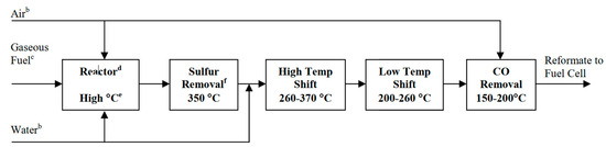
Figure 11. Schematic of the steps in a typical fuel processor for low-temperature SOFCs [35].
Different fuel can be used in SOFCs, including natural gas, diesel, gasoline, hydrogen, ethanol, methanol, ammonia, etc. [38][39][305,306]. Hydrocarbon fuels can provide higher theoretical efficiency (above 91%) compared to pure hydrogen in a fuel cell (83%). For example, if methane is used as the fuel in a SOFC, it can produce eight electrons per oxidizing every single molecule of methane, while hydrogen can only produce two electrons. This increased energy efficiency can be boosted using hydrocarbons with a more complex structure such as ethanol, butane, pentane, etc. Those fuels can also be transported and stored using the current facilities and infrastructure available in the local gas grids and fuel stations [40][38][31,305]. Among the hydrocarbons, propane and butane have higher density and are of greater interest. Butane has higher energy efficiency, while propane can give the highest exergy efficiency [41][307]. Due to the low-temperature needed for reforming ethanol and methanol, they are the most preferred fuels in the low-temperature region and portable SOFC applications [38][305].
In summary, while hydrogen is the most common fuel for the closed systems (such as space crafts), natural gas is the most preferred type of fuel for small and stationary plants. In addition, high sulfur diesel can be used in heavy vehicles, jets, and military applications. For light vehicles and low-temperature applications, on-board hydrogen and liquid fuels such as gasoline and methanol are preferred. Other fuels, such as ethanol, biomass, refuse-derived fuels, etc., have also been investigated for their potential applications in the SOFC systems [35][36][41,303].
4. Technological Aspects for Low-Temperature Stack Design
4.1. Stack Design Technologies
Solid oxide fuel cell stacks consist of individual cells, sealants, and connectors. Generally, the efficiency of a SOFC stack is remarkably lower than that of the individual cells. The critical factor that has a significant influence on the performance of a stack is the interface contact between the current collector and cell [42][308]. A single cell cannot obtain a high current and voltage output; thus, the individual cells should be connected in parallel or series to improve the overall voltage and power density [14][35][14,41]. In addition to the conventional planar and tubular designs, novel stack design technologies can be divided into several classifications such as integrated planar (IP), cone-shaped, flat-tube, honeycomb, microtubular, etc. The IP design (Figure 12a) is a stack design that can be considered as a cross between the tubular and planar structure and can provide lower weight and costs for the current collector and the whole SOFC. It also offers an improved cell performance mainly due to the short electronic and ionic path [43][44][309,310]. However, it needs a careful design and choice of materials as well as optimization of microstructure to overcome the problems with sealing and current collector integrity [45][311]. The cone-shaped design (Figure 12b) can be considered as a tubular SOFC with high thermal stability. By fitting each cone into another, a self-supported tubular structure will be formed. Thus, the integrated cells in this design can offer flexibility to the stack, along with a high power density [46][312]. However, challenges similar to those in IP-SOFCs remain elusive [45][311]. The Flat-tube design (Figure 12c) is a modified tubular design with a higher power density and thermal resistance than the conventional tubular design. In this design, the fuel moves through the gas channels while the oxidants pass through a porous media located between the cells [47][48][313,314]. The honeycomb design (Figure 12d) possesses the advantages of tubular and planar structure and is composed of several honeycomb channels which serve as the fuel and oxidant paths. This design can be either as the electrode- or electrolyte-supported geometries with delivering a high power density and mechanical strength [49][315]. The micro-tubular geometry is a type of tubular design in which the tube diameter is smaller than 3–5 mm [50][316]. Since the power density inversely proportional to the tube diameter, this design provides a higher power density than the conventional tubular SOFCs [51][45][52][79,311,317]. Moreover, the small size of the tube reduces the thermal gradient; thereby, the microtubular SOFCs can provide a better thermal shock resistance [53][54][318,319]. Other types of cell and stack designs, such as SOFCs with novel electrolyte design and wet-impregnated SOFCs, have been investigated by some scholars. These designs may offer higher electrochemical performance compared to the conventional designs; however, their long-term stability and low mechanical strength have yet to be studied in details [45][311].

Figure 12.
a) Integrated planar (IP)-SOFC cell design [43], (
b) cone-shaped SOFC design (1. anode; 2. electrolyte; 3. cathode; and 4. current collector) (Reproduce with permission from [55], Institute of Physics (IOP), 2007), (
c
d) honeycomb SOFC design (Reproduced with permission from [45], Elsevier, 2016).
The stack designs are complex engineering units that have their own pros and cons. Although the IP-SOFCs could provide a relatively better electrochemical performance at lower costs, the integrity of the current collector and sealing are the main challenges with this design [45][311]. The cone-shaped design offers higher thermal shock resistance and power density; however, due to the complex design and problems with current collector integrity, its fabrication is complex and challenging [46][312]. The flat-tube SOFCs could also provide high thermal shock resistance and power density but similar to the cone-shaped design, those suffer from engineering and design complexity issues [45][311]. The honeycomb design, on the other hand, could improve the durability and mechanical strength of the stack, but the challenges associated with the stack fabrication, current collector integrity, and electrical lead have hindered its application in SOFCs. The microtubular design could potentially provide high volumetric output power, good thermal shock resistance, and rapid start-up. However, the poor current collection is the main disadvantage of this design [56][321].
4.2. Synthesis Methods and Conditions
Synthesis conditions (temperature, pressure, dwelling time, etc.) for the ceramic powders and fabrication materials can significantly affect the microstructure and the electrochemical performance of the fabricated SOFCs. Optimizing the cell structure and its properties such as relative density, microdomain formation grain size, grain boundaries, agglomeration, impurities, thermal history, etc., can improve the mechanical and electrical properties of the fabricated cells and stacks [57][58][59][110,322,323]. Shemilt and Williams [60][324] employed compression-molding and dry-pressing to fabricate SDC electrolytes and found that the compression molded-samples can provide a higher grain boundary activation energy compared to the dried pressed samples. Mori et al. [61][325] investigated the effect of different morphologies on the electrical conductivity of SDC samples and found that the spherical particles possessed higher conductivity than the elongated ones mainly due to the smaller microdomain in those samples. Gibson et al. [62][326] reported the grain boundary conductivity linearly correlates to the amount of porosity. It has also been reported that finer microstructure can increase the TPB length and result in a more uniform particle/pore distribution in the bulk of the materials. The synthesis method has a significant impact on particle size and distribution. Optimization of the ratio of the solid phases in the sample can improve the electrochemical performance [63][64][327,328]. Naimaster et al. [65] [329] investigated the effect of microstructure on the performance of I-T SOFCs and reported that decreasing the grain size down to 2 µm could improve the current density in the order of 2–3 A·cm−2. They also noted that porosity and tortuosity did not have a significant impact on the performance; however, a relationship between these two parameters can be useful for adjusting the constituents of the MIEC composite (particularly in the case of LSCF-GDC). The work also showed that the anode diffusion loss could be lower than that of the cathode layer. This work can be exemplified as a successful microstructural improvement study by obtaining the maximum power density of about 0.162 W·cm−2 to about 0.789 W·cm−2 and reduced activation overpotential (~29%) and ohmic loss (68%).
As discussed above, the SOFC electrodes should have a suitable amount of porosity, while the electrolyte should be fabricated as dense as possible. Thus, choosing a proper fabrication method is of significant importance in achieving a high-performance SOFC with desirable properties [66][330]. In addition, the conventional solid-state reaction synthesis, the other fabrication techniques such as sol–gel [67][331], hydrothermal [68][332], citrate sol–gel [69][58], polymeric salt composition [70][333], co-precipitation [71][216], combustion synthesis [72][334], glycine-nitrate and citrate [73][74][152,335], impregnation [75][233], infiltration [76][249], Pechini [77][147], spray pyrolysis [72][334], ionic gelation [25], etc., have been used for the fabrication of various individual SOFC layers. For instance, in the case of microtubular SOFCs, gel-casting, extrusion, cold isostatic press, etc., have been extensively investigated for fabricating the supporting microtubes [66][330]. As another example, the tape casting method can be used for the fabrication of both electrodes and electrolyte layers with various thicknesses and lower costs. However, this method has some challenges associated with the multiple drying process required, as well as the high crack sensitivity of the fabricated cells [78][40]. Screen printing can reduce the cracking problems during sintering and is capable to be used for large-scale fabrication of high-quality SOFC films. However, providing a high-quality ink is an important challenge in this method [79][336]. Onbilgin et al. [80][337] compared the screen-printing and the tape-casting methods and reported that the tape-cast samples could provide a relatively higher performance compared to those samples prepared by the screen-printing method. Overall, the fabrication method and sintering conditions, as well as the starting materials, have a significant impact on the cell output performance. The preferred method selected for the fabrication of the L-T SOFCs depends on the simplicity, feasibility, and costs [81][338].