Abrasive water jet machining (AWJM) is a very useful non-conventional machining for the cutting of dissimilar materials at once. It is a flexible process that generates low thermal damage to the machined surface as there is no continuous tool-material con- tact along the machining process. Compared to conventional processes such as milling, abrasive particles are used in water jet machining. These particles have cutting edges that allow the machining of the material by overlapping of small impacts that deform the material. At each instant, a quantity of abrasive particles travels in the water jet in order to perform the cut.
- AWJM
- Hybrid Structure
- Surface Quality
- Geometric defects
- Machining
1. Introduction
Non-conventional processes are currently attracting a lot of interest because they can provide a very high performance.
Abrasive water-jet machining (AWJM) can be a very interesting choice in this context. Dr. Mohamed Hashish is considered as the father of this machining technology, who proposed a series of models and background on water-jet machining of metals[1][2][3] [20–22]. It is a flexible process, capable of achieving high productivity in the form of high material removal rates. In addition, it generates low machining forces and, especially, generates a very small temperature range compared to conventional processes. This is of great interest because it minimizes the probability of deterioration or degradation of the polymeric matrix of the composite material[4] [23]. From an environmental point of view, this process has high efficiency by using water at high pressure, that can be reused later, reducing its negative impact on the environment. Compared to conventional technologies, there is no physical tool, and there is much less wear on auxiliary elements, reducing process costs as it can be used over a wide range of materials with different machinability at the same time[5] [19]. In addition, metalworking fluids (MWF) are not required[6] [24].
Nevertheless, this technology has different defects associated with the process. The AWJM process generates regions with different surface quality depending on the thickness of the material. It also generates variations of kerf widths at the entrance and exit of the material in the form of conicity or taper angle, mainly caused by the dispersion of the kinetic energy of the water jet. These defects concern the micro and macro-geometric deviations of the final product. These variations are key parameters for the evaluation of the geometry within the design and assembly specifications.
2. Process
Water-jet machining uses a mixture of fluid and solid particles that is accelerated and causes the deformation or removal of the target material on which it is impacted. The jet can be composed of any liquid, but for economic and environmental reasons, the liquid used is usually a mixture of water and air. The water, by presenting a higher density, applies a higher impact pressure during machining[7][8][9][10] [25,26].
In this process, a third element consisting of small abrasive particles is added to the air and water flow. These can be of any material, shape or size, and must be harder than the material to be machined in order to remove it and cause as little damage as possible[7][9][10] [25,27,28]. These particles usually show irregular geometries and sharp edges. However, more rounded particles can be used which generate deformations and residual compressive stresses[11] [11].
Abrasive particles are absorbed by the vacuum created in the mixing chamber, due to the pressure drop at the jet periphery caused by the acceleration of the water jet. In this chamber, the particles are mixed with the water jet at high speed and both are passed through a focusing nozzle, also called a mixing chamber, which is slightly larger in diameter than the hole through which the water passes before. This tube has homogenizing the fluid jet with the particles set as the main function (Figure 12).
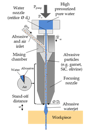
Figure 12. Representative diagram of an abrasive water-jet machining process adapted from[12].
Representative diagram of an abrasive water-jet machining process adapted from [29].
If the particles to be used have a reduced size and an irregular geometry with sharp edges, the impact speed they reach is very high, close to 1000 m/s[13][14] [30,31], which allows these particles to penetrate into the material to be machined, generating a permanent crater[7][9] [25,27]. It should be noted that abrasive particles may collide inside and reduce final size when mixed with water flow.
Finally, when they are ejected by the nozzle, the jet expands freely in a divergent way, reducing its power density and thus the machining capability if the distance between the nozzle and the material is very high[15][16][17] [32–34].
The removal of material during abrasive water-jet cutting is based on the continuous impact of solid particles on the material. This process can be divided into four sub-mechanisms in which abrasive particles erode the material surface: cutting, fatigue, melting, and brittle fracture[18][19] [35,36]. These mechanisms do not act separately, but in combination. In this way, the final cuting effect is generated by the geometric superposition of craters formed by the particles that have impacted the material[20][21] [37,38]. It is necessary to differentiate between the behavior of ductile materials and fragile materials, since due to their different properties they show different behaviors[10][22] [28,39]. Ductile materials suffer plastic deformation during cutting, while brittle materials are subjected to cutting through fracture.
However, it is a process that can present a series of limitations. Due to the loss of kinetic energy during machining and the different machinability of the materials, various defects can occur. Regions of different surface quality have been detected in several investigations generating striations in the final region known as lag defect. At the same time, the resistance of the materials to be machined reduces the kinetic energy of the water jet. This produces a difference between the upper width of the cut and the lower width generating a defect known as taper angle. This defect is enhanced by the erosion effect of the abrasive particles in the initial moments. These produce a rounding on the edges, generating an area affected by erosion.