Water monitoring sensors in industrial, municipal and environmental monitoring are advancing our understanding of science, aid developments in process automatization and control and support real-time decisions in emergency situations. Sensors are becoming smaller, smarter, increasingly specialized and diversified and cheaper. Advanced deployment platforms now exist to support various monitoring needs together with state-of-the-art power and communication capabilities. For a large percentage of submerged instrumentation, biofouling is the single biggest factor affecting the operation, maintenance and data quality. This increases the cost of ownership to the extent that it is prohibitive to maintain operational sensor networks and infrastructures. In this context, the paper provides a brief overview of biofouling, including the development and properties of biofilms. The state-of-the-art established and emerging antifouling strategies are reviewed and discussed.
- biofouling
- instrumentation
- biomimetics
- materials
- marine
- freshwater
- coatings
- optical sensors
1. Introduction
The adhesion and growth of microorganisms at the interface between any non-sterile medium and a solid surface is a widespread phenomenon in most environments on Earth. The development of disturbing or unwanted biofilms on surfaces is a major problem due to the accumulation of biomass that causes reduced efficiency, contamination, corrosion and failure of engineered components. This process is often undesirable in synthetic materials and surfaces from a technological, health or economic perspective. Therefore, the undesirable biological adhesion and growth on surfaces has been called biofouling[1][2]. Biofouling in the aquatic environment shortens the life-time of immersed structures, increases fuel consumption of ships and affects the functioning and data quality of water sensors [3]. The biofilm attached to vessels is responsible for the transport of invasive species from one ecosystem to another [4][5][6].
To control this biofouling problem, different antifouling solutions, such as coatings, have been used throughout history. Many of these coatings incorporate biocides, which base their effectiveness on generalised and non-selective toxicity to marine organisms. The impact of these biocides on the environment has led to the creation of legislation to regulate their use [5]. For example, the environmental impact caused by tributyltin (TBT), included in antifouling coatings, was first banned on 525 m vessels in most industrialised countries[6] and subsequently a worldwide ban by the International Maritime Organization (IMO) for all vessels in 2008. Due to the increasing environmental scrutiny of copper (Cu
2+) and co-biocides, there is a renewed interest in the economic impacts of fouling on ships and a greater effort to develop effective non-toxic coatings[7].
The requirement for effective antifouling solutions is not limited to the shipping industry and extends to infrastructure for renewable energy, telecommunications and ocean and coastal observations. In the context of ocean monitoring, biofouling has long been considered a limiting factor and is recognised as one of the main obstacles to autonomous environmental monitoring in aquatic environments [8][9]. Much of the equipment currently used to monitor coastal and ocean waters relies on sensors incorporated into various platforms like buoys, subsea moorings and surface and subsurface vehicles [10]. All immersed components, including operational components (membranes, optical windows and electrodes), housings and mooring components are subject to biofouling and prone to irreversible damage [11]. For a large percentage of deployed instrumentation, biofouling is the single biggest factor affecting the operation, maintenance and data quality. This is particularly true for coastal and marine deployments. The Alliance for Coastal Technologies has estimated that up to 50% of operational budgets are attributed to biofouling, depending on location and season[12]. Such costs are associated with shorter deployment periods, loss of data due to sensor drift, frequent maintenance requirements and a shorter lifespan of the instrumentation. With recent advances in electronics, power management and battery life, and communication, biofouling is the key factor limiting the length of time a water monitoring instrument can stay deployed, particularly in long-term, continuous monitoring applications[12][13]. With a projected increase in operational architectures at the regional and global scales, to provide a backbone for active networking of autonomous platforms and environmental observations, the role of effective antifouling strategies for in situ sensors is paramount. Despite the importance of protection against biofouling for in situ instrumentation, progress towards an ideal operational strategy has been slow. Although many techniques have been developed and tested in the last decade very few of them have been implemented commercially. In many cases, the strategies used have been developed for the mature shipping industry and applied in their original or altered form to the instrumentation. The most notable developments and advancements have come from industry, with the development of specialised, tailored design solutions.
2. Sensor Materials
Table 1.
| Material | Sample Use of Material in a Sensor | Sensor Type or Application |
|---|---|---|
| Metals | ||
| Titanium | Sensor housings | Available in commercial turbidity sensors |
| Fused Silica | ||
| Optical windows | ||
| Most | ||
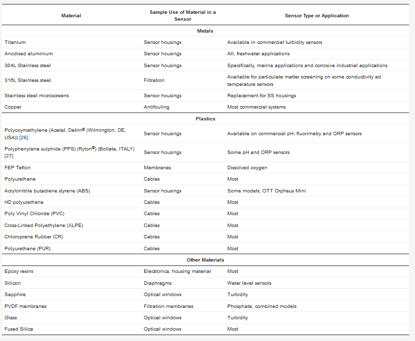
In order to deter saltwater corrosion, manufacturers leverage superior materials. An example of this is the use of molybdenum in marine-grade stainless alloys, including 316 stainless steel alloy [28]. This type of material can be found in enclosures for portable power distribution systems designed exclusively for marine locations, industrial lighting products and more. Other types of marine-grade materials include the following: AH36, DH36 and EH36 (carbon steel); grade 5052 and 6061-T6 (aluminium); and C65500 (silicon bronze) [20][30][31].
Marine-rated devices for use in the marine environment on board ships or in submerged or exposed marine facilities and structures may also be treated with resilient coatings to ensure adequate protection from saltwater corrosion[11][32] Galvanization is a common method for achieving such features, which involves dipping the material or product in hot zinc [
Advancements in material sciences have led to many manufacturers moving away from PVC and stainless-steel sensors due to the challenges in the operating environment. It has been seen that even materials such as steel can suffer corrosion processes produced by sulphate-reducing bacteria (SRB). These bacteria can produce hydrogen sulphide and acidic metabolites, such as acetic acid. It is suggested that the presence of hydrogen sulphide and acidic metabolites have a significant effect on the cathodic processes attacking these steel surfaces [34]. Therefore, new materials that can withstand salt water and biofouling, for example, polymers or titanium, are being used for sensors because they really increase the durability of the sensor. A trend towards the increased use of titanium is noticed among different sensor developers, such as Valeport (Totnes, Devon, UK) or YSI, a Xylem brand (Yellow Springs, OH, USA); others, like Turner Design (San Jose, CA, USA) in their C3 and C6-P models[35][36], use a delrin
®
3. Antifouling Strategies for Sensors
Figure 1), generating visual artefacts, blurred images or noise, affecting the quality of the images and data. The problem is even more severe with optical sensors.
Figure 1A illustrates the impact of even a short deployment of as little as one month on an optical sensor. The “slime” that forms has the potential to block the sensor signal and requires steps to remove it. In this case a mechanical wiper is attached.
Figure 1B shows the optical element completely blocked. The data quality of the sensors that are impacted by a biofilm, where from an unprotected sensor, shows increasing data drift in
Figure 1C. The properties of light are used to take the measurements; therefore, a slight deposit of biofilm on the optical elements can interfere with the measurements.
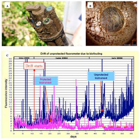
Figure 12.
A
B) transmissometer after 30–39 days in Throndheim harbour (Norway) during summer[11]; (
C
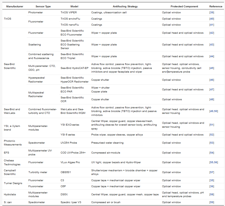
Table 2.
| Manufacturer | Sensor Type | Model | Antifouling Strategy | Protected Component | Reference | |||
|---|---|---|---|---|---|---|---|---|
| TriOS | Photometer | TriOS VIPER | Coatings, ultrasonication cell | Optical window | [39] | |||
| Fluorometer | TriOS enviroFlu | Coatings | Optical window | [40]Anodised aluminium | Sensor housings | All, freshwater applications | ||
| TriOS nanoFlu | Coatings | Optical window | [41] | 304L Stainless steel | Sensor housings | Specifically, marine applications and corrosive industrial applications | ||
| Sea-Bird Scientific | Fluorometer | Sea-Bird Scientific ECO Fluorometer |
Wiper + copper plate | Optical head and optical windows | [42] | 316L Stainless steel | Filtration | Available for particulate matter screening on some conductivity ad temperature sensors |
| Scattering | Sea-Bird Scientific ECO Scattering Sensor | Wiper + copper plate | Optical head and optical windows | [43] | Stainless steel microscreens | Sensor housings | Replacement for SS housings | |
| Combined scattering and fluorescence | Sea-Bird Scientific ECO Triplet | Wiper + copper plate | Optical head and optical windows | [44] | Copper | Antifouling | Most commercial systems | |
| Multi-parameter: CTD, ODO, pH | Sea-Bird HydroCAT-EP | Active flow control, passive flow prevention, light-blocking, active biocide (TBTO) injection, passive inhibitors and copper faceplate and wiper | Optical head. optical windows, sensor housing, conductivity cell and temperature probe | [45] | Plastics | |||
| Hyperspectral Radiometer | Sea-Bird Scientific HyperOCR Radiometer | Copper shutter | Optical window | [46] | Polyoxymethylene (Acetal, Delrin® (Wilmington, DE, USA)) [26] | Sensor housings | Available on commercial pH, fluorimetry and ORP sensors | |
| Multispectral Radiometer | Sea-Bird Scientific ECO PAR | Wiper + shutter Copper plate |
Optical head and optical windows | [47] | Polyphenylene sulphide (PPS) (Ryton®) (Bollate, ITALY) [[27] | Sensor housings | ||
| Sea-Bird Scientific OCR | Some pH and ORP sensors | |||||||
| Copper shutter | Optical windows | FEP Teflon | Membranes | Dissolved oxygen | ||||
| 50 | ] | Polyurethane | Cables | Most | ||||
| YSI, a Xylem brand | Multiparameter-modules | YSI EXO-series | Central Wiper, copper guard, copper sleeves/mesh, antifouling sleeves for overall sensor body, antifouling spray | Optical head, optical windows and sensor housing | [51] | Acrylonitrile butadiene styrene (ABS) | Sensor housings | Some models; OTT Orpheus Mini |
| YSI 6 series | Probe wiper, copper sleeves, copper alloys | Optical head and optical windows | [52] | HD polyurethane | Cables | Most | ||
| Poly Vinyl Chloride (PVC) | Cables | Most | ||||||
| Cross-Linked Polyethylene (XLPE) | Cables | Most | ||||||
| [ | 48 | ] | ||||||
| Sea-Bird and Wet-Labs | Combined fluorometer-turbidity and CTD | Wet-Labs and Sea-Bird Scientific WQM | Active flow control, passive flow prevention, light-blocking, active biocide (TBTO) injection and passive inhibitors | Optical head. optical windows and sensor housing | [49, | Chloroprene Rubber (CR) | Cables | |
| Photonic Measurements | Spectrometer | UV254 Probe | Pressurised water cleaning | Optical window | [53] | Most | ||
| EFS | Multiparameter UV-probe | COD UV-Probe 254+ | Compressed air-module | Optical window | [54] | Polyurethane (PUR) | ||
| Chelsea Technologies | Fluorometer | VLux Algae Pro | UV light, copper bezels and Hydro-Wiper | Optical window | [55,56] | |||
| Campbell Scientific | Turbidity meter | OBS501 | Shutter/wiper mechanism + biocide chamber + copper alloys | Optical window | [57] | Cables | Most | |
| Turner Designs | Fluorometer | C3 | Copper tape + mechanical copper wiper | Optical window | [35 | Other Materials | ||
| ] | ||||||||
| Fluorometer | C6P | Copper tape + mechanical copper wiper | Optical window | [36] | Epoxy resins | Electronics, housing material | Most | |
| Hydrolabs | Multiparameter-modules | DS5X | Central Wiper, copper guard, copper mesh, copper tape | Optical head, optical windows, pH and temperature probes | [58] | Silicon | Diaphragms | Water level sensors |
| S::can | Spectrometer | Spectro::lyser V3 | Compressed air or brush | Optical window | [59] | Sapphire | Optical windows | Turbidity |
| PVDF membranes | Filtration membranes | Phosphate, combined models | ||||||
| Glass | Optical windows | Turbidity | ||||||
3.1. Wiper Technologies
The simplest methods to remove biofouling from submerged structures such as boat hulls is the pressure cleaning of these structures with water, air or mechanical cleaning using brushes and wipers[60]. However, although these methods are simple and sometimes solve the problem of biofouling, they are not entirely feasible when applied to sensors with sensitive components.
4.1. Wiper Technologies
Figure 3. A mechanical antifouling system based on wipers must consider the material used in the wipers themselves, avoiding scratching the lens surface or other critical parts of the device. Its design should consider easy removal for replacement or repair as these often wear out. Some of these systems can be a sponge, offering a softer but less durable option than a brush as used in the YSI 6 series [52](YSI, a Xylem brand, Yellow Springs, OH, USA). Many manufacturers of oceanographic instruments, such as the YSI EDS series (YSI, a Xylem brand, Yellow Springs, OH, USA), Hydrolab’s Self-Cleaning sensors (Loveland, CO, USA) or Wet Labs/Sea-Bird Bio (Bellevue, WA and Philomath, OR, USA), present built-in wipers working as a part of the mechanism of the sensor or independently as an accessory that is coupled to the measuring instrument (
Figure 3). Due to the effectiveness of this strategy, many companies like Zebra-Tech (Nelson, New Zealand) specialize in the exclusive development of wiper technologies compatible with multiple probes, such as its Hydro-Wiper model[56]. The latter category functions as stand-alone wipers, which are often included as accessories and optional, coming at an extra cost. In terms of modularity, such wipers are designed to fit a wide range of sensors from the same manufacturer or they are specific to certain sensor versions. Although wipers are commonly used in commercial sensors, on-sensor power is required, which can limit the deployment duration. Damage due to abrasion can occur or macrofouling can obstruct movement. Today, a larger, fully integrated central wiper (YSI EXO-series [
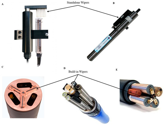
Figure 3.
A) Ponsel Dissolved Oxygen and Turbidity Sensors + antifouling wiper[62]; (
B
C
D) YSI EXO 2 multi-parameter sonde[61]; (
E) YSI 6 series multi-parameter sonde[65] (reproduced with permission of © 2020 YSI, a Xylem brand, Yellow Springs, OH, USA and Sea-Bird Scientific, Bellevue, WA, USA).
3.2. Biocide Generation Systems
4.2. Biocide Generation Systems
Pseudomonas aeruginosa biofilms, showing that aeration of a mixture of a foaming agent in conjunction with a common biocide was toxic to the bacteria making up the biofilm [66]. The use of foam disinfectants allows the reduction of the volume of biocides for disinfection. Another technique used in the cleaning of sensors is the use of chlorine and bromine solutions. These solutions are based on slow-dissolving chlorine (trichloroisocyanuric acid) and bromine have been used in closed optical systems to clean detection windows[67].
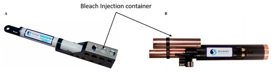
Figure 4.
A) HydroCAT-EP, Sea-Bird Scientific[45]; (
B) Water Quality Monitor (WQM) Wet-Labs and Sea-Bird Scientific sensor [50] (reproduced with permission of Sea-Bird Scientific, Bellevue, WA, USA).
Davis and collaborators developed a method based on the use of solid bromine tablets placed inside a perforated container to reduce the effects of biofouling in optical systems[67]. This solution prevented the growth of biofouling, but it was difficult to maintain consistent concentrations. The effectiveness and usefulness of the chemical supply method for combating biofouling is unpredictable. Rajagopal et al. studied the response of the fouling hydroid
Cordylophora caspia
Protection based on TBT (tributyl-tin) leaching and paints for biofouling protection was extremely efficient. TBT was banned by the International Maritime Organization (IMO) in 2008. These compounds are considered to be highly toxic to the environment[69][70]. However, despite the ban, the American company Sea-Bird Scientific (Bellevue, WA, USA) continues to get approved by the Environmental Protection Agency (EPA) for this biocide[42][44][50]. Their strategy employs TBT rings in a pumping system coupled with a conductivity sensor. This way, when the conductivity sensor takes a measurement, the pumping system is switched on and its concentration is diluted. The pump flushes the sampled water and quickly moves a new sample into the flow path so that conductivity and oxygen measurements are more accurate. Water does not flow freely through the flow path so it stays saturated with the antifouling chemicals[45].
Following the ban of TBT-based products, alternatives containing copper (Cu)-based compounds were developed. Copper-based compounds that are less toxic than TBT, cobiocides, also called boosters, were used to enhance the antifouling performance of copper-based coatings [6][7]. Copper-based antifouling paint can be classified into two groups. The first group are slow-release films, releasing cuprous oxide into the surrounding environment by leaching. The second type are ablative antifouling paints that have a continuously toxic surface. The released bivalent Cu
2+ interferes with the enzymes on cell membranes, avoiding cellular division[71][72]. However, some studies have shown that copper is not completely efficient as a biocide on its own, as some of the common marine algae have tolerance to this compound[73]. There is evidence of the diffusion of these compounds in many countries (Europe, North America and Japan) with significant concentrations of copper in marinas and harbours[7]. This has been shown to cause the generation of biocide resistance by bacteria, especially in estuarine environments where most ships and aquaculture structures are moored[74][75]. Because of this, this element must be used in combination with biocide reinforcements such as Irgarol
®
®
® 211 (Dow Chemical Company, Midland, MI, USA), Dichlofluanid, Ziram, Thiram, Chlorothalonil, Kathon 5287 or Maneb/Zineb to be effective[76][77][78][79].
Figure 5). Sensors such as the Campbell Scientific OBS501(Loughborough, UK) have a specific shutter designed to protect the optics. The OBS501 is constructed to prevent sand grains or packed sediment from getting wedged between the shutter and sensor body, which inhibits the shutter’s movement. To do this, the OBS501’s shutter and body were designed to eliminate parallel surfaces between moving parts wherever possible. The probe also uses a flushing action that moves the sediment down and out of the cavity behind the shutter. This antifouling and cleaning system incorporated into the OBS501, called the ClearSensor Method[80], is able to sense whether the shutter motor is working harder than normal. If it is, the shutter moves slightly back and forth to dislodge the sediment before opening or closing completely. For additional protection, the company offers a plastic sleeve, as well as a copper sleeve that can provide additional protection, especially in sea water.
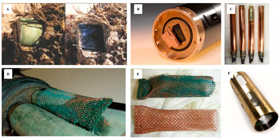
Figure 5.
A
B
C
D
E) antifouling copper “sock” used for conductivity sensors; (
F) copper guard[82](reproduced with permission of Sea-Bird Scientific (Bellevue, WA, USA) and the permission of Campbell-Scientific (Loughborough, UK).
However, most sensors have exposed sensor heads. This eliminates many of the problems that can occur with pumping systems or shutter closures. In contrast to these open systems, protection against biofouling is more complicated. In some experiments on optical sensors carried out by Kerr and collaborator, a gel doped with biocides is used; however, there are problems with opacity affecting the performance once deployed[83].
3.3. Antifouling Coatings
4.3. Antifouling Coatings
34.4. Electrochemical Antifouling Methods
An alternative to the use of fouling resistant coatings is to use electrochemistry. One of the methods that has been investigated by several groups is the generation of chlorine and hypochlorous acid by electrolysis of the water as a method for the prevention of fouling of marine sensors. This process occurs through an electrode adjacent to the sensor or through a conductive layer on the sensor surface. However, the disadvantage of this approach is that the coating can be physically degraded during the application of the potential in sea water[9].
Direct electrification of the organisms in different ways, by direct transfer of electrons from electrodes to the fouling organisms, has also been tested. Graphite-silicon electrodes[95] and titanium nitride (TiN) [96] have also been tested to combat biofouling. The application of electric pulses has been tested[97] in cooling systems. Electric pulses with amplitudes of the order of kV/cm, with durations of microseconds, proved to be effective on hydrazoans. Delauney et al. have tested biofouling protection in modified TriOS fluorometers [98](Ammerland, Germany). They used a transparent conductive tin dioxide (SnO
2) coating with optimised physicochemical properties by the CNRS-LISE UPR15 laboratory in collaboration with the Ifremer Technological Research Group in Brest, France[99][100] (
2
4
4
4
3
2
Figure 6.
A
B
Spears and Stone employed different methods based on copper screens[101]. These techniques based on galvanic anodes or sacrificial anodes are also employed as a corrosion protection system for buried or submerged metal structures. They are made of a metal alloy with a higher tendency to oxidize than the metal of the structure to be protected, with a more negative reduction potential. The potential difference between the two metals implies that the galvanic anode corrodes, preserving the structure to be preserved, since the anode material will be consumed in preference to the metal of the structure. This would inhibit growth in the structures while the surrounding areas would have significant marine fouling. Although this method is particularly effective in preventing barnacles and oysters from adhering to surfaces and is commonly used on ship hulls to protect propellers, the disadvantage is that it is expensive to install on sensors.