High torque density is a desirable feature of electrical machines used in traction applications, such as electric vehicle (EV)/hybrid electric vehicle (HEV) propulsion, wind turbines, more electric air-crafts, etc. The flux-modulated permanent magnet (FMPM) machine is considered as one of the most promising candidates to achieve high torque density. The incorporated gearing effect is ideal in reducing the rotating speed and amplifying the output torque of the FMPM machines.
- flux-modulated machine
- high torque density
- topology revolution
- traction application
Note: The following contents are extract from your paper. The entry will be online only after author check and submit it.
1. Introduction
With increasing concerns on environmental pollution and energy shortage, electrical machines have been widely used in traction applications, such as electric vehicle (EV)/hybrid electric vehicle (HEV) propulsion [1], wind turbines [2], drones [3], and more electric aircrafts [4][5][6][4–6]. Generally, the electrical machines for traction applications need to have the following characteristics.
- High torque for effective propulsion, especially at low speeds;
- High efficiency over a wide torque and speed range to reduce electricity consumption;
- Robust structure and good fault tolerance capability;
- Compact size and acceptable cost.
Induction machines used to be the leading choices for traction applications because of the robust structure, low cost, and simple control technique. However, with the development of high energy density permanent magnet (PM) materials, PM machines are gradually taking the leading position, because PM machines can achieve higher torque density and higher efficiency [7, [7][8]8]. The PMs can be surface mounted on the rotor [9] [9] or inserted into the rotor [10], and they can be magnetized in a special pattern referred to as Halbach array [11] to make the air-gap flux more sinusoidal and increase torque and efficiency accordingly. The PMs can also be employed on the stator, and stator–PM machines can be developed with the help of flux modulation. Since the cooling of the stator is more efficient than the cooling of the rotor, PMs in the stator have a low risk of being demagnetized by the high temperature. Meanwhile, stator–PM machines have robust rotors with only salient poles and can be used in harsh environments.
The basis of flux modulation is the permeance difference between the iron and the air, and specific harmonic components can be induced to facilitate electromagnetic torque generation. One of the famous applications of flux modulation is the magnetic gear shown in Figure 1, which has three components, an inner rotor, an outer rotor, and a modulation ring sandwiched between the two rotors [12]. The flux modulation effect caused by the permeance difference between the ferromagnetic segments and the air is the key to ensure effective coupling of the inner rotor PM field and the outer rotor PM field, and to achieve efficient torque transmission accordingly. The design principle is that the pole-pairs of the modulation ring should equal the sum of the pole-pairs of the inner rotor and the pole-pairs of the outer rotor. Any of these three components can be fixed, and the other two components can work as a magnetic gear. This magnetic gear can achieve a high torque density, 50–150 kNm/m3, and low maintenance because there is no physical contact between the input and the output.
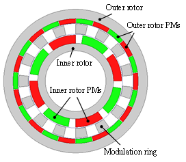
Figure 1. Configuration of the co-axial magnetic gear.
By incorporating the magnetic gearing effect into the PM machine design, flux-modulated PM (FMPM) machines can be developed. Actually, many of the widely investigated machine concepts belong to FMPM machines, such as magnetic-geared PM (MGPM) machines, doubly salient PM (DSPM) machines, flux-switching PM (FSPM) machines, flux-reversal PM (FRPM) machines, Vernier PM (VPM) machines, etc. One common initiative of developing FMPM machines is to further increase the torque density. The incorporated gearing effect is effective in increasing rotor pole-pairs, reducing rotor speed, and amplifying output torque. The current research on FMPM machines mainly focuses on proposing novel machine concepts and developing advanced control techniques.
2. Surface-Type FMPM Machines
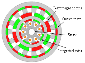
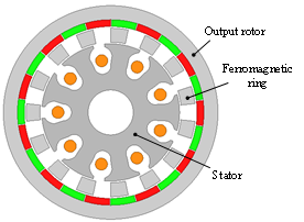
In this section, FMPM machines with the PM’s surface mounted on the rotor or the stator teeth are discussed, which are referred as surface-type FMPM machines. One typical topology of the surface-type FMPM machines is the MGPM machine shown in Figure 2a. By connecting the outer rotor of a PM machine with the inner rotor of a magnetic gear to form an integrated rotor, the output torque of the PM machine can be amplified directly by the magnetic gear, and the torque density can be as large as 87 kNm/m3, as reported in [13]. However, there are two rotating components and three air gaps in this machine, which makes the mechanical structure complicated. Manufacturing is another challenge because it is very difficult to assemble all the components accurately. If the PM machine is designed with the same pole-pairs as the inner rotor of the magnetic gear, then the magnetic fields generated by the PM machine rotor and by the inner rotor of the magnetic gear are the same; therefore, the integrated rotor can be eliminated, and the machine structure can be simplified [14], as shown in Figure 2b. In the new machine, the ferromagnetic ring is the key to ensure effective interaction between the high-speed armature field and the low-speed PM field to generate electromagnetic torque. The pole-pairs of the ferromagnetic ring are equal to the sum of the pole-pairs of the armature field and the pole-pairs of rotor, which is similar to the design principle of the magnetic gear. This machine can also be recognized as replacing the inner rotor of the magnetic gear with a machine stator.
 |
 |
|
(a) |
(b) |
Figure 2. Configurations of the magnetic-geared permanent magnet (MGPM) machines: (a) MGPM machine with three air gaps; (b) MGPM machine with two air gaps.
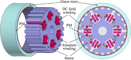
The pseudo direct drive PM (PDD-PM) machine is another typical topology of the surface-type FMPM machines, as shown in Figure 3, in which the high-speed PM machine and the magnetic gear share a high-speed rotor [15] [15]. The other set of PMs with large pole-pairs is surface mounted on the stator teeth, and the modulation ring acts as the output rotor. This machine can achieve a torque density higher than 60 kNm/m3 under natural air-cooling condition, and a power factor larger than 0.9 can be achieved. As a result of the contactless feature of the magnetic gear, one of the predominant features of the PDD-PM machine is the overload protection ability. When the load torque is larger than the pull-out torque, slip between the two rotors of PDD-PM machine occurs without causing serious mechanical damage. However, the slip may cause undesirable consequences such as an incorrect commutation signal, dangerous over speeding of the high-speed rotor, and loss of power transfer. A slip detection and prevention method was proposed in [16]. By detecting the slip and reconfiguring the control to maintain synchronization of the two rotors, normal operation can be swiftly resumed after overload disappears.
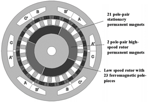
Figure 3. Configuration of a pseudo direct drive PM (PDD-PM) machine [15].
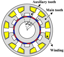
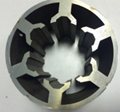
When the stator is designed with open slots, the stator teeth can achieve a good flux-modulating effect as the ferromagnetic segments, and a new machine concept that is referred to as a surface Vernier PM (SVPM) machine can be developed, as shown in Figure 4. Different from traditional surface-mounted PM machines with the same rotor pole-pairs and armature pole-pairs, the SVPM machine has larger rotor pole-pairs than armature pole-pairs. The stator teeth act as the flux modulators to reduce the rotating speed of the armature field and enable effective coupling between the armature field and the PM field. The design and operating principles of SVPM machine were analytically investigated using the classical permeance function in [17], and the results indicated that the SVPM machine can achieve two to three times back electromotive force (EMF) and torque of the conventional PM machine with the same volume. The influence of different pole ratios and the winding pole-pair number on the torque performance of the SVPM machine was reported in [18], and the results showed that the electromagnetic torque increases to its peak value with the increasing of the pole ratio, but it then decreases due to the large PM leakage. In low-speed applications, the rotor of the SVPM machine needs to be designed with large pole-pairs, and the stator usually has overlapping windings to achieve a low pole-pair number of an armature field with a large number of stator slots. The overlapping windings increase the length of end windings and reduce torque and efficiency accordingly. A good solution is to design the stator with auxiliary teeth, and a split-tooth SVPM machine was developed in [19], as shown in Figure 5. The auxiliary teeth act as the flux modulators, and the stator slot number can be reduced. With the same magnet usage, the split-tooth SVPM machine can achieve 20% higher torque than the regular SVPM machine. By adding a concentrated field winding into the stator slots as shown in Figure 6, the split-tooth SVPM machine can achieve hybrid excitation and DC flux weakening control [20].
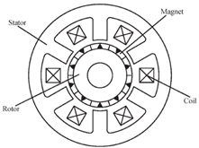
Figure 4. Configuration of a surface Vernier PM (SVPM) machine [18].
 |
 |
 |
|
(a) |
(b) |
(c) |
Figure 5. Split-tooth SVPM machine: (a) Machine configuration; (b) Stator core; (c) PM rotor [19].
|
(a) |
(b) |
Figure 6. Hybrid-excited split-tooth SVPM machine: (a) 3D structure; (b) Cross-sectional view [20].
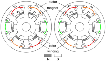
The rotors of all the aforementioned surface-type FMPM machines have PMs mounted on the surface. Since the PMs have a relatively weak mechanical strength, an additional sleeve is needed to protect the PMs from being damaged by the large centrifugal force when the rotor runs at high speeds. The protection sleeve increases the air-gap length and reduces the output torque. Flux-reversal PM (FRPM) machines are good candidates to solve this problem, which employ PMs on the surface of the stator teeth and the rotor has a robust structure with only salient poles. Considering the magnetization methods, FRPM machines can be divided into two categories, as shown in Figure 7. In Figure 7a, the magnets on the adjacent stator teeth are reversely magnetized, which is referred to as NS-SN. While in Figure 7b, the magnets on all the stator teeth are magnetized in the same way, which is referred as NS-NS. The back EMF prediction method based on air-gap field modulation theory was developed in [21]. The influence of adjacent teeth magnet polarities on the performance of FRPM machines was comprehensively investigated in [22], and the results revealed that FRPM machine with four magnet pieces mounted on each stator tooth and magnets on adjacent stator teeth that are of opposite polarities can achieve the largest output torque. Large PM leakage flux is one of the major drawbacks of FRPM machines, which causes partial magnetic saturation and results in a low power factor. An asymmetric stator pole FRPM machine was developed to reduce the leakage flux [23], whose configuration is shown in Figure 8. The asymmetric arrangement of magnets generates biased coil flux linkage, which results in torque improvement as well. The simulation and experimental results showed that this asymmetric stator pole FRPM machine can achieve 24.16% higher torque than its conventional counterpart, and a power factor of 0.76 was measured.
 |
|
|
(a) |
(b) |
Figure 7. Configurations of flux-reversal PM (FRPM) machines with two magnetization methods: (a) Magnets on the adjacent stator teeth that are reversely magnetized (NS-SN); (b) Magnets on all the stator teeth are magnetized in the same way (NS-NS) [21].
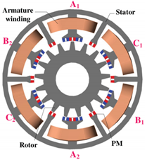
Figure 8. Configuration of an asymmetric stator pole FRPM [23].
The PMs in all the aforementioned surface-type FMPM machines are radially magnetized. Actually, the surface-type FMPM machines can also be designed with axial flux, which are even more promising in achieving compact structures and high torque densities. Figure 9 shows the configuration of an axial-flux MGPM machine for power split application in hybrid electric vehicles [24], and comparative investigation showed that it can achieve significantly higher torque than the conventional axial-flux YASA machine [25]. The application of an axial-flux MGPM machine in a wind turbine was investigated in [26], and a prototype with a torque density of 7.8 kNm/m3 was designed, fabricated, and tested. A less conservative alternate design capable of achieving 60.6 kNm/m3 was also simulated to demonstrate the topology’s potential for high torque densities. An axial-flux SVPM machine was developed in [27], as shown in Figure 10. A torque density of 31.9 kNm/m3 was measured when the current density is 5.8 A/mm2, and the proposed machine is very suitable for EV/HEV propulsion because of the high torque density.
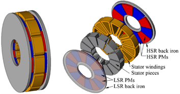
Figure 9. Configuration of an axial-flux magnetic-geared PM (MGPM) machine [24].
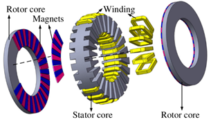
Figure 10. Configuration of an axial-flux SVPM machine [27].
3. Spoke-Type FMPM Machines
As a result of the flux focusing effect, spoke-type PM machines have been proven capable of generating higher air-gap flux density than surface-type PM machines, and they can achieve higher torque density accordingly. The employment of spoke-type PM arrays have been investigated in various PM machines, including FMPM machines. One representative spoke-type FMPM machine concept is the flux-switching PM (FSPM) machine, which has been widely investigated in recent years. The typical configuration of the FSPM machine is shown in Figure 11. The PMs are inserted into the stator teeth and the rotor only has salient poles, which is mechanically robust and suitable for high-speed applications. Since the cooling of the stator is more efficient than the cooling of the rotor, PMs in the FSPM machines have a lower risk of being demagnetized by high temperature. All the PMs are magnetized circumferentially, and the adjacent PMs are magnetized in opposite directions. The armature winding comprises concentrated coils, and each coil is being wound on a stator tooth. When the rotor rotates, bipolar flux linkage waveforms can be generated in the armature winding. The FSPM machines are promising in achieving a high torque density because of the flux focusing effect and the potential of using more PM materials. The coils can also be alternatively wound on the stator teeth, and the winding configurations and optimal stator/rotor pole combinations were investigated in [28]. An outer-rotor FSPM machine for in-wheel light traction applications was developed in [29], as shown in Figure 12. The optimal stator/rotor pole combination to maximize the back EMF and minimize cogging torque was studied, and the flux-weakening capability of the machine was analyzed and further improved by segmental PMs with iron bridges. Axial FSPM machines have also been intensively investigated for traction applications. The influence of rotor tooth shaping on the cogging torque of an axial FSPM machine was studied in [30]. A yokeless axial FSPM machine was proposed to increase the winding space and torque capability, in which the two rotors are displaced by 180 electrical degrees [31]. Compared with a conventional axial FSPM machine, this novel yokeless structure exhibits higher torque density and significantly lower cogging torque. A rotor excited axial FSPM machine was developed in [32], which demonstrates 18% higher torque density than its radial flux counterpart and is promising for EV propulsion.
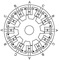
Figure 11. Configuration of a flux-switching PM (FSPM) machine [33].
 |
 |
|
(a) |
(b) |
Figure 12. Configuration of an outer-rotor FSPM machine: (a) Cross-sectional view; (b) Explored view [29].
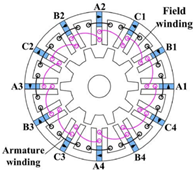
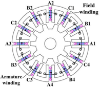
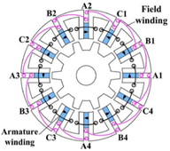
Since FSPM machines employ PMs on the stator, it is easy to realize hybrid excitation and DC flux weakening control by adding an additional field winding to the stator slots. Figure 13 shows the configurations of three different hybrid-excited FSPM machines, which have PMs at different locations of the stator teeth [34]. The flux regulation theories and principles of these three machines were analyzed, and the results showed that the PM-top machine exhibits reversal flux-regulation functions to that in the PM-bottom one. The PM-middle one can be considered as the combination of the PM-bottom machine and the PM-top machine, and it has the weakest flux-regulation capability. The effect of the field winding can be strengthened by adding an iron bridge to the outer radius of the machine, and the cost is slightly reducing the torque density [35]. The aforementioned FSPM machines have series hybrid excitation because the flux paths of the field winding and the PMs are in series, and the PMs have a risk of being demagnetized by the field current. An E-core FSPM machine was proposed to achieve parallel hybrid excitation, as shown in Figure 14, in which the PMs are safe from being demagnetized by the field current [36]. The flux-weakening capability of the E-core hybrid-excited FSPM machine can be further improved by designing the winding with five phases [37], which makes it suitable for electric vehicle propulsion. An FSPM memory machine with hybrid PMs was developed in [38], whose topology is given in Figure 15. In addition to NdFeB, low coercive force (LCF) magnets were employed on the stator. Since the working point of LCF magnets can be adjusted by applying DC current pulse, this machine can achieve flux weakening control without generating additional copper loss, and the machine can operate with high efficiency in the high-speed region.
 |
 |
 |
|
(a) |
(b) |
(c) |
Figure 13. Hybrid-excited FSPM machines: (a) PM-bottom; (b) PM-top; (c) PM-middle [34].
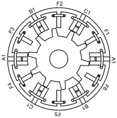
Figure 14. Schematic of an E-core hybrid FSPM machine [36].
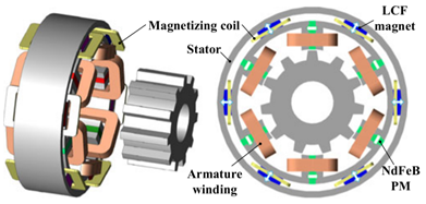
Figure 15. Topology of a FSPM memory machine [38].
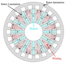
A Vernier machine is another major application of spoke-type PM array. As a result of large PM leakage flux, it is difficult for the SVPM machines discussed in Section 2 to achieve a high power factor. A good solution is to employ double stators with a half teeth pitch displacement to provide complementary flux paths [39], as shown in Figure 16. The PMs are inserted into the rotor, which are sandwiched between the two stators, and the adjacent rotor pole drives flux across the inside/outside air gap; then, the flux travels in the outside/inside stator iron and back across the air gap into the rotor. The specific relative position of the two stators and spoke PM array combine the two stators together from the view of magnetic field, and it ensures a high power factor of 0.83 according to the measurement of a prototype. The design procedure of this high-power factor VPM machine includes the design parameter initial value setting, analytical sizing equation, and key geometrical relationship formulas, and design parameter optimization was comprehensively studied in [40]. It was found that the optimal stator pole-pairs for maximum torque increase as the outer diameter increases. For a given diameter, the larger the pole ratio, the lower the optimal stator pole-pairs. The torque performance of the double stator spoke-type VPM machine was compared with an industrial interior permanent magnet (IPM) machine in [41], which showed the double stator spoke-type VPM machine demonstrates 33% higher torque production using ferrite PMs at the nominal temperature compared to that of the commercial IPM machine using rare-earth PMs. Figure 17 shows an improved structure by removing the inner stator windings [42], which eliminates the heat source inside the rotor and effectively reduces the size and weight of the inner stator.
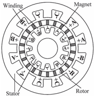
Figure 16. Configuration of a double stator Vernier PM (VPM) machine [39].
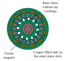
Figure 17. Configuration of a double stator VPM machine without inner stator winding [42].