The transport membrane condensers (TMC) process can be considered as a hybrid of a heat exchanger and membrane condensers.
- transport membrane condensers
- ,membrane heat exchangers
- flue gas dehydration
1. Heat Transfer Efficiency of the TMC
First, the advantage of the TMC over conventional impermeable heat exchangers (HEXs) should be compared. Researchers have investigated the use of an impermeable HEX mainly to recover the latent heat [1][31]. Compared to other HEX configurations, modeling a HEX in high moisture conditions is very complex due to the formation of heat and mass boundary layers in the presence of non-condensable gases. A theoretical foundation was laid out by Levy and Jeong et al. [2][3][4][7,9,32] which showed that heat transfer efficiency of a condensation HEX can be 3.5-fold higher compared to the simple convection HEX.
Bao et al. [5][33] built upon the previous models to incorporate a TMC-based membrane HEX. Fascinatingly, the results show that a TMC HEX can exhibit a 50%–80% higher Nusselt number compared to the impermeable HEX at the same condensation conditions. The primary reason for such enhancement is the permeation of condensate water from the HEX surface. In the TMC, the condensate forms within the membrane pores and permeates through the membrane. In contrast, a condensate film layer forms on the surface of an impermeable HEX, appending significant thermal resistance and lowering the heat transfer efficiency. Their work certainly opened an exciting topic not only for flue gas dehydration but potentially many other applications with condensable vapors.
In the TMC, the inlet cooling water gets heated by the condensing vapor, absorbing their latent and sensible heat. However, with respect to the thermal energy recovery, the usefulness of the heated water is yet questionable. In order for the outlet water stream to be energetically useful and valuable, it needs to be heated up to at least 50 °C or higher. If the outlet water stream temperature is below 50 °C, it has very low energetic value and may not justify the use of the TMC over other available technologies. This is one of the most important aspects of the TMC and is discussed further below.
Encouragingly, the numerical results by Soleimanikutanaei and Lin et al. [6][7][8][34–36] show that the water exit temperature can be elevated up to 57 °C. However, most other works on the TMC have only focused on water extraction, and the value of an outlet water stream was not assessed in detail. In South Korea, for example, the latent heat recovered from the boiler steam vapor (outlet cooling water stream shown in Figure 2) circulates through a small city to heat up the households before discharge.
2. Capillary Condensation
In TMC technology, it is very important to understand the peculiar concept of capillary condensation and its impact on TMC performance. The saturation vapor pressure of water is primarily a function of temperature and it can be estimated using the Antoine equation. At the flue gas outlet temperatures of 50–80 °C, the water saturation vapor pressure is about 0.1–0.5 bar. However, thermodynamically, the saturation pressure can decrease within constrained curved spaces, such as in membrane pores [9][10][37,38]. It can be theoretically estimated using the Kelvin equation, as calculated in Figure 15.
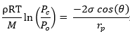
where ρ is the density of the condensate, R is the universal gas constant, T is the absolute temperature, M is the molecular weight of the condensable compound, Pc is the capillary condensation pressure, Po is the vapor saturation pressure at a planar interface, σ is the interfacial tension, θ is the contact angle, and rp is the membrane pore radius.
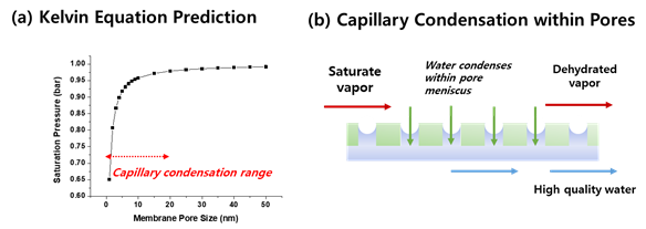
Figure 15. (a) Estimation of water saturation pressure at 100 °C as a function of membrane pore size, (b) schematic illustration of capillary condensation of water vapors within membrane pores.
The water saturation pressure at 100 °C in an open atmosphere is 1 bar. However, within the membrane pores, as shown in Figure 15a, the saturation pressure decreases. Particularly, a sharp decrease can be predicted below 20 nm pore sizes. Membrane researchers have investigated this phenomenon since the 1970s on porous Vycor glass material [39] and have shown that mass transfer through a membrane via a capillary condensation mechanism can be significantly faster than vapor permeation. Asaeda et al. [11][12][40,41] exploited this interesting phenomenon to separate azeotropic mixtures (alcohol/water) with high selectivity. In theory, higher selectivity can be achieved as liquid condensate within the pores can prevent the transport of other gases.
Wang et al. [13][28] proposed to exploit this phenomenon on the TMC process. The authors have shown that water transfer via a capillary condensation mechanism can be 5-fold faster compared to that of the Knudsen diffusion. In addition, the separation ratio (with respect to non-condensable gases) improved by a factor of 100.
Based on this report, many follow-up works on the TMC claim to exploit the capillary condensation phenomenon, yet the experiments were not designed to clearly show its effect. Chen et al. [14][8] specifically designed an experiment to show that capillary condensation indeed takes place and that it improves dehydration efficiency. The authors in this paper increased the cooling water temperature higher than the feed gas dew point and showed that there is still detectable water flux. More work needs to be carried out to clearly prove the capillary condensation effect on TMC performance.
Notably, from the engineering perspective, it is not strictly necessary to induce capillary condensation as long as the temperature gradient between the feed gas and cooling water is maintained. The temperature gradient will spontaneously condense the water vapors onto the membrane surface. Therefore, many reported works simply employed membranes with pore sizes much larger than 20 nm (up to 1 μm) to test the TMC process. In fact, the report by Li et al. [15][42] specifically confirmed that surface condensation occurs more than capillary condensation for 1 μm ceramic membranes.
It should be stressed that the concept of capillary condensation only becomes important when the outlet water quality needs to be high. For instance, Wang et al. [13][16][28,29] claimed that the extracted water quality was high enough to be used as the boiler feed water, which must be ultrapure distilled water quality. This result is surprising given that the permeated water quality from the vapor permeation membrane did not meet the boiler feed water requirement [12]. Further investigation is necessary on this front as well.
3. TMC Data and Parametric Study
It can be seen that the TMC is relatively a complex process that requires careful tuning of operation parameters. Since the first pioneering reports of Wang et al., [13][15][28,29] many researchers have investigated the use of the TMC in lab-scale and in pilot-scale.
Relevant literature on TMC-based dehydration, to the best of the authors’ knowledge, is compiled and summarized in Table 12. Several trends can be deduced from the reported literature on the TMC. First, although scattered, the data show similar trends with respect to the TMC performance. The key operational parameters, such as flue gas temperature, cooling water temperature, flue gas flow rate, cooling water flow rate, and flue gas humidity, have been thoroughly investigated with respect to water flux and heat transfer efficiency.
Qualitative trends have been well summarized by Gao et al. [17][43]. Most of the obtained trends are intuitive and logical. For example, water recovery efficiency is proportional to the temperature difference between the flue gas and cooling water. In addition, the efficiency of heat recovery mostly improved with water recovery in tandem. However, unfortunately, it is yet difficult to compare the literature data, and new dimensionless numbers should be developed for the TMC process.
Secondly, TMC performance does not seem to depend on the membrane pore size. It can be seen in Table 12 that TMC water flux lies in the range between 1 and 40 kg·m2·hr, and there is no correlation with membrane pore size. This is an important trend, as it suggests that the current TMC process may be completely condensation-limited, not permeation-limited.
The work by Kim et al. [18][6] showed that water flux has a linear relationship with the inlet water vapor flow rate (shown in Figure 26a). Regardless of the operation conditions, the obtained water flux was linearly proportional to the inlet water vapor flow rate. Such a relationship indirectly indicates that water flux is not permeation-limited, as all the water condensed on the membrane surface is transferred. Note that the observed water flux was much lower than the maximum possible flux of the membranes (about 90 kg.m−2.hr−1 at ΔP of 0.03 bar). Li et al. [19][44] also obtained similar results, where most resistance is in the condensation step, not in the membrane permeance.
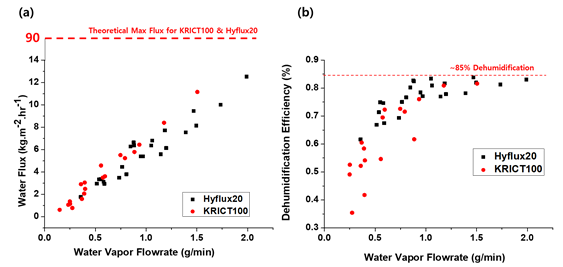
Figure 26. (a) Water flux plotted against the inlet water vapor flow rate, showing a linear relationship. (b) Dehumidification efficiency, performance comparison, and dehumidification efficiency (reprinted with permission from [18][6]).
This result potentially hints that employing nanoporous membranes (<20 nm) is preferred from the water quality perspectives, but such ceramic membranes are certainly more expensive. The effect of membrane pore size on selectivity is discussed below.
On the other hand, the dehumidification efficiency plateaus at around 85% (Figure 26b) due to the lack of thermal driving force above this point. A similar maximum plateau was observed in other works [14][7][20][8,35,45].
Thirdly, pilot-scale studies have also been carried out with up to 50,000 membrane bundles with different configurations [16][19][21][42,44,46]. Many systematic experimental and numerical studies have shown that staggered configuration of membrane bundles have a higher Nusselt number and hence better TMC performance.
Table 12. Summary of literature data on the TMC process.
Membrane | Pore Size (Material) | Inlet Gas | Temperature (°C) | Cooling Stream Temperature (°C) | Water Flux | (kg/m 2/h) | Heat Flux | (MJ/m 2/h) | Note | Year, Ref | ||||||||||||||||||
1 μm (Ceramic) | 49–53 | 30–36 | 10–22.23 | Flue Gas, Pilot Scale | 2021 [21] | [46] |
||||||||||||||||||||||
1 μm (Ceramic) | 40–60 | 15–35 | 0.5–2.93 | 3.6–9 | Flue Gas, Lab Scale | 2020 [22] | [47] |
|||||||||||||||||||||
30, 50, 200 nm (Ceramic) | 45–60 | 15–30 | 1.7–4.8 | Flue Gas, Pilot Scale, SO2 | 2020 [23] | [48] |
||||||||||||||||||||||
2, 12, 30 nm | (Monolith Ceramic) | 90–110 | 45–66 | 2–3 | 4–5 | CO2 Capture, Lab-scale | 2020 [24] | [49] |
||||||||||||||||||||
1 μm (Ceramic) | 50 | 22 | 5–43.65 | 75–110 | Flue Gas, Pilot Scale | 2020 [19] | [44] |
|||||||||||||||||||||
1 μm (Ceramic) | 50 | 24–36 | 20–35 | 60–80 | Flue Gas, Pilot Scale, Numerical | 2020 [16] | [42] |
|||||||||||||||||||||
0.4 nm | (NaA zeolite sieve) | 35–55 | 12–38 | 2–16 | Flue Gas, Lab Scale | 2020 [25] | [50] |
|||||||||||||||||||||
1 μm (Ceramic) | 40–50 | 20–25 | 16–22 | 50–70 | Flue Gas, Lab Scale | 2020 [26] | [51] |
|||||||||||||||||||||
4 nm, 10 nm (Ceramic) | 90–110 | 45–65 | 6–14 | 27–30 | CO2 Capture, Lab-scale | 2019 [27] | [52] |
|||||||||||||||||||||
4 nm (Ceramic) | 90–110 | 45–65 | 6–14 | 27–30 | CO2 Capture, Lab scale | 2019 [28] | [53] |
|||||||||||||||||||||
4 nm Ceramic | 90–110 | 15–60 | 4–6 | CO2 Capture, Lab scale | 2019 [29] | [54] |
||||||||||||||||||||||
1 μm (Ceramic) | 40–60 | 20–32 | 15.8 | Flue Gas, Lab Scale | 2019 [30] | [55] |
||||||||||||||||||||||
1 μm (Ceramic) | 40–60 | 20–32 | 15.77 | 15 | Flue Gas, Lab Scale | 2019 [17] | [43] |
|||||||||||||||||||||
10 nm (Ceramic) | 25–70 | 30–50 | 1.5–2.2 |
| Flue Gas, Lab Scale, SO2 | 2019 [31] | [56] |
|||||||||||||||||||||
6–8 nm (Ceramic) |
[32]70–80 |
70–80 |
20–43 | 1–7 | 10–15 | Flue Gas, Numerical | 2019 [7] | [35] |
||||||||||||||||||||
40, 90 nm (Ceramic) | 50–80 | 20 | 1–13 | Flue Gas, Lab Scale, SO2 | 2019 [18] | [6] |
||||||||||||||||||||||
13 nm (Ceramic) | 62 | 20 | 10 | Flue Gas, Lab Scale, | 2018 [33] | [57] |
||||||||||||||||||||||
20, 30, 50, 100 nm (Ceramic) | 50–70 | N/A | 1–3 | Flue Gas, Lab Scale | 2018 [32] | [58] |
||||||||||||||||||||||
6–8 nm (Ceramic) | 70–80 | 20–43 | N/A | Flue Gas, Numerical | 2018 [6] | [34] |
||||||||||||||||||||||
N/A | 50–90 | 10–20 | 10 | Flue Gas, Numerical | 2017 [34] | [59] |
||||||||||||||||||||||
20 nm (Ceramic) | 80–120 | 25–50 | 4–6 | 18–25 | Flue Gas, Lab Scale | 2017 [20] | [45] |
|||||||||||||||||||||
20 nm (Ceramic) | 50–70 | 16–65 | 1–15 | 2–15 | Flue Gas, Lab Scale | 2017 [14] | [8] |
|||||||||||||||||||||
8–10 nm ceramic | 45–85 | N/A | 2–15 | 5–45 | Flue Gas, Lab Scale | 2016 [35] | [60] |
|||||||||||||||||||||
6–8 nm Ceramic | 45–85 | 33 | 8–22 | 30–74 | Flue Gas, Lab Scale | 2015 [36] | [61] |
|||||||||||||||||||||
N/A | 90–110 | 45–115 | CO2 Capture, Numerical | 2015 [37] | [62] |
|||||||||||||||||||||||
6–8 nm (Ceramic) | 65–95 | 20–45 | N/A | Flue Gas, Numerical | 2015 [5] | [33] |
||||||||||||||||||||||
6–8 nm (Ceramic) | 82 | 44 | 1–7.2 | Flue Gas, Numerical | 2013 [8] | [36] |
||||||||||||||||||||||
6–8 nm (Ceramic) | 65–85 | 33–55 | 3–7 | Flue Gas, Pilot Scale | 2012 [13] | [28] |
4. TMC Materials (Ceramic vs. Polymeric)
Compared to vapor separation and conventional membrane condenser processes, all of the employed TMC membranes are inorganic ceramic membranes, as shown in Table 1. The main reason is the high thermal conductivity of ceramic materials, which is necessary to efficiently extract the heat energy from the condensing surface into the cooling waterside. The thermal conductivity of porous ceramic membranes can be estimated with different methods, and it varies widely from 1.4 to 21.84 W·m
Compared to vapor separation and conventional membrane condenser processes, all of the employed TMC membranes are inorganic ceramic membranes, as shown in Table 2. The main reason is the high thermal conductivity of ceramic materials, which is necessary to efficiently extract the heat energy from the condensing surface into the cooling waterside. The thermal conductivity of porous ceramic membranes can be estimated with different methods, and it varies widely from 1.4 to 21.84 W·m
−1
·K
−1 [38]. In comparison, typical polymer thermal conductivity is in the range of 0.1–0.5 W·m
[44]. In comparison, typical polymer thermal conductivity is in the range of 0.1–0.5 W·m
−1
·K
−1 [39]. Thus, from the heat transfer perspective, the use of ceramic membranes is highly preferred.
[63]. Thus, from the heat transfer perspective, the use of ceramic membranes is highly preferred.
However, ceramic membranes are seldom applied in real membrane processes due to their high cost and difficulties in handling (brittleness). In addition, a significant amount of membrane, up to 10
5
m
2
for a 500 MW plant, would be required to handle the voluminous flue gas flowrate. A ceramic membrane module generally has a much lower module area/volume ratio (m
2
/m
3
) than polymeric membrane modules.
On the other hand, polymeric membranes may offer a promising alternative. Polymeric membranes can be more cost-competitive, and they are mechanically more flexible and resistant. In addition, a much higher area/volume ratio is possible with a hollow fiber module. However, the thermal conductivity of porous polymeric material is relatively low. Kim et al. [18] calculated and compared the surface temperature and radial temperature profile of ceramic and polymeric membranes, as shown in Figure 3. It can be seen that the steady-state surface temperature of polymeric membranes can be 5 to 10 °C higher than that of ceramic membranes. Such analysis indicates that the TMC is certainly feasible with polymeric membranes, albeit less efficient.
On the other hand, polymeric membranes may offer a promising alternative. Polymeric membranes can be more cost-competitive, and they are mechanically more flexible and resistant. In addition, a much higher area/volume ratio is possible with a hollow fiber module. However, the thermal conductivity of porous polymeric material is relatively low. Kim et al. [6] calculated and compared the surface temperature and radial temperature profile of ceramic and polymeric membranes, as shown in Figure 7. It can be seen that the steady-state surface temperature of polymeric membranes can be 5 to 10 °C higher than that of ceramic membranes. Such analysis indicates that the TMC is certainly feasible with polymeric membranes, albeit less efficient.
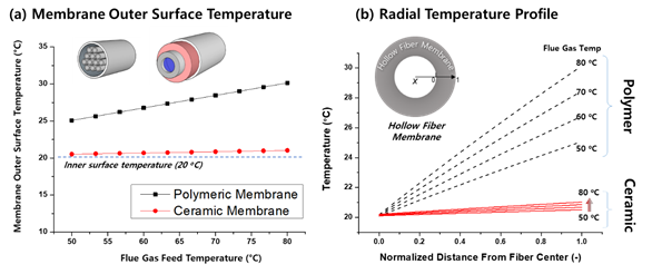
Figure 37. Comparison of ceramic and polymeric materials on (a) membrane outer surface temperature and (b) radial temperature profile as a function of flue gas temperature (reprinted with permission from [18][6]).
Nevertheless, we expect that polymeric membranes will become a cost-effective option for the TMC in near future. An interesting study can be carried out in the future to increase the thermal conductivity of polymeric membranes by incorporating fillers, yielding mixed matrix membranes with high thermal conductivity. For instance, carbonous fillers such as graphene nanoplates possess a thermal conductivity as high as 5000 W·m−1·K−1 [39][63]. In addition, extended fins could be implemented onto the membrane outer surface to improve the heat transfer rate.
5. Water Dehydration Performance Comparison and Water Purity
Figure 48 summarizes the water flux between the two membrane-based dehydration processes. Based on the simple water flux comparison, the TMC may be 10- to 100-fold more effective in the flue gas dehydration process. However, more importantly, two other factors must be compared simultaneously: the quality of the recovered water and the usefulness of the recovered energy.
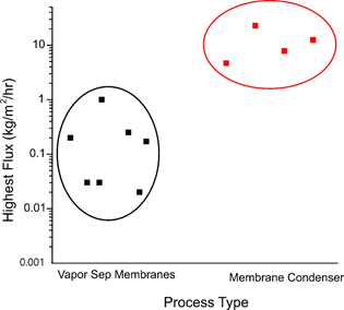
Figure 48. Comparison of membrane-based dehydration processes. Vapor separation membranes are polymeric and TMC membranes are ceramic.
First, the quality of the recovered water must be discussed in detail. When the TMC was first introduced by the GTI company, Wang et al. [13][15][28,29] claimed that captured water quality from the TMC is boiler-feed quality. However, the reported data have not been reproduced by other works. The quality of boiler feed water must be extremely high [40][41][64,65] as it is ultrapure RO water. Even the water captured via dense vapor separation membranes [42][12] did not pass the quality threshold. Thus, there is not enough data yet to confirm that TMC water can be used for boiler feed water. Nevertheless, the quality of captured water is sufficiently high to be used for other uses such as cooling water and cleaning water.
The quality of recovered water depends on its ability to reject NOX and SOX contaminants. Several works investigated SOx flux in the TMC process [6,48,56]. Although flue gas passes through an FGD unit, it still contains ppm-level NOx and SOx contaminants. SO2 reacts with O2 to form , which immediately reacts with H2O vapor to form H2SO4 and exists in equilibrium as . Kim et al. [18][6] reported that TMC membranes show unusually high rejection toward SOx derivatives despite their small size (<1 nm) compared to the membrane pore size (20 nm). SOx selectivity over water vapor reached above 100, which is much higher than the simple Knudsen selectivity of 1.8 (square root of molecular weight ratio). The exact mechanism of this selectivity is unknown, but it could be attributed to higher preferential condensation of water vapor within the membrane pores. The work by Cheng et al. [48] reported similar trends.
On the other hand, Gao et al. [31][56] investigated the desulfurization efficiency of the TMC using composite ceramic membranes. The objective of this work was to facilitate the permeation of SOx derivative into the cooling waterside. Clearly, there is yet no consensus on SOx permeation in the membrane community. However, the higher the quality of permeated water, the higher the value; hence, it is desirable to yield high SOx/water selectivity. In addition, more works on NOx selectivity need to be investigated, as it is generally more troublesome than SOx derivatives in power plants.
Another very important issue in TMC technology is the usefulness of the recovered energy. In the TMC, flue gas thermal energy is extracted into the cooling water. In order for this energy to have some energetic value, the outlet temperature should be at least 50 to 60 °C. Although researchers of the GTI company reported the outlet temperatures can reach up to 57 °C [5][6][7][8][33–36], most lab-scale results in Table 2 maintained constant cooling water temperature and did not investigate the outlet temperature. In fact, some works reported the temperature increases only a few degrees. It should be noted that the outlet temperature is mostly a process parameter that can be controlled, not the membrane parameter. The process and operation parameters need to be controlled to yield outlet temperatures above 50 °C. More experimental and numerical analysis is required on this front as well.
From an engineering perspective, a water stream with a temperature around 30 °C has almost no value; hence, we cannot claim to have recovered any energy from flue gas. But a stream with a temperature above 50 °C may have some energetic value, although not highly valuable. One potential usage of 50 °C water is to apply as membrane distillation (MD) feed water; such a process could be interesting, even feasible, if seawater is used as the TMC feed water.