Here, we review various novel/modified interfacial polymerization (IP) techniques for the fabrication of polyamide (PA) thin film composite (TFC)/thin film nanocomposite (TFN) membranes in both pressure-driven and osmotically driven separation processes. Although conventional IP technique is the dominant technology for the fabrication of commercial nanofiltration (NF) and reverse osmosis (RO) membranes, it is plagued with issues of low membrane permeability, relatively thick PA layer and susceptibility to fouling, which limit the performance. Over the past decade, we have seen a significant growth in scientific publications related to the novel/modified IP techniques used in fabricating advanced PA-TFC/TFN membranes for various water applications. Novel/modified IP lab-scale studies have consistently, so far, yielded promising results compared to membranes made by conventional IP technique, in terms of better filtration efficiency (increased permeability without compensating solute rejection), improved chemical properties (crosslinking degree), reduced surface roughness and the perfect embedment of nanomaterials within selective layers. Furthermore, several new IP techniques can precisely control the thickness of the PA layer at sub-10 nm and significantly reduce the usage of chemicals.
- interfacial polymerization
- polyamide
- thin film composite
- membrane
- nanomaterials
Please note: Below is an entry draft based on your previous paper, which is wrirren tightly around the entry title. Since it may not be very comprehensive, we kindly invite you to modify it (both title and content can be replaced) according to your extensive expertise. We believe this entry would be beneficial to generate more views for your work. In addition, no worry about the entry format, we will correct it and add references after the entry is online (you can also send a word file to us, and we will help you with submitting).
1. Introduction
Thin film composite (TFC) membranes are the dominant technology for the commercial market of nanofiltration (NF) and reverse osmosis (RO) process. Compared to the microporous membranes, the TFC-NF and -RO membranes show better separation efficiency in producing high-quality water, as a result of their dense skin layer made of a crosslinked polyamide (PA) network [1]. Generally, TFC-NF membranes are used in water purification, wastewater treatment, pharmaceutical and biotech industries, among others [2], while TFC-RO membranes are mainly for brackish water and seawater desalination process [3]. In 2017, the global NF and RO membrane market was valued at $643 million and $6.9 billion, respectively, and was projected to reach $955 million and $13.5 billion by 2025 [4][5][4,5]. The estimated compound annual growth rate of over 5.0% for the period between 2018 and 2025 reflects the ever-increasing potential of TFC membranes for industrial applications.
In the 1950s, Loeb and Sourirajan invented the first polymeric membrane made of cellulose acetate with ~99% rejection efficiency for removing dissolved ions from seawater [6]. Nevertheless, its application was hampered by low water permeability (~0.14 L/m2·h·bar) coupled with poor chemical and pH tolerance. Furthermore, cellulose-based membranes also exhibited low temperature resistance that rendered them incompatible for use at elevated temperatures [7]. The cellulose-based membranes for desalination were soon phased out after the TFC membrane was developed by Cadottee and his colleagues in the 1970s [8]. This composite membrane was produced by depositing thin PA selective layer over a microporous membrane substrate via the interfacial polymerization (IP) technique. Aside from showing better chemical and pH tolerance, the TFC membrane demonstrated a similar salt rejection efficiency with an added advantage of a higher water permeability (~0.74 L/m2·h·bar) than cellulose-based membrane, when it was first reported.
Over the past two to three decades, the TFC membrane perhaps is the fastest-growing membrane technology for the treatment of industrial water and wastewater [5], as its properties (PA layer and substrate) can be independently optimized to achieve the desired separation performance [9]. Figure 1 illustrates the typical construct of a commercial TFC membrane showing three distinct layers, i.e., the top PA layer (responsible for the membrane selectivity) supported by microporous substrate and thick polyester nonwoven backing. The bottom polyester layer is particularly important for mechanically supporting the entire membrane sheet to withstand high-pressure filtration. Although TFC membranes are widely used in many industries; without facing major technical issues, their performances are far from ideal with the major hurdle being the trade-off effect between membrane water permeability and salt rejection [10][11][12][10,11,12], alongside vulnerability to organic/inorganic fouling, as well as chlorine attack.
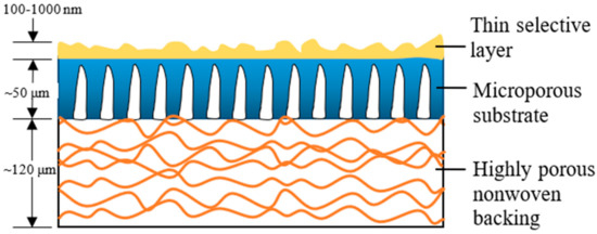
Figure 1.
Concerted efforts into improving membrane characteristics and consequently filtration performance have generally centered on integrating inorganic nanomaterials to either the PA layer or microporous substrate [13][14][15][13,14,15]. The resultant thin film nanocomposite (TFN) membrane has since become popular among membrane scientists, from the time when it was first reported in 2007, by Jeong et al. [16]. Compared to the use of nanomaterials to modify substrate, utilizing nanomaterials for PA layer modification has greater significance for water application, as it is the layer that is directly exposed to the feed solution. While there are several comprehensive reviews available on this topic [17][18][19][20][21][17,18,19,20,21], they largely cover the impacts of different nanomaterials on the physiochemical properties of TFN membrane and how changes in membrane intrinsic characteristics could affect membrane performance.
Although laboratory-scale studies generally yielded promising results after the PA layer is modified by nanomaterials, a larger-scale TFN membrane manufacture remains challenging. It has to do with the problematic development of defect-free PA layer for long-term operation, resulting from the poor compatibility between the polymer and the inorganic nanomaterials as well as their uneven distribution within the thin PA layer [22][23][24][22,23,24]. The loss of precious nanomaterials during IP processing and/or their leaching from TFN membrane during filtration are also major concerns for their industrial implementation [25]. To address these issues, modification on the conventional IP procedure is required to improve the surface properties of the PA-nanomaterials layer. There has been a significant number of modified IP processes or newly developed IP techniques used for the TFN membrane fabrication over the last decade [26][27][28][26,27,28]. These include the filtration-based IP [29] and spin-based IP [30]. In certain cases, the water fluxes of the resultant membranes fabricated by modified or new IP technique were reported to increase by an order without compromising salt/solute rejection, in comparison to the conventionally prepared TFC membrane [31][32][33][31,32,33].
Modifications of conventional IP technique for developing extremely thin PA layer for ultrafast solvent permeation have also been described. Karan et al. [32] reported that a high permeation rate sub-10 nm PA layer could be synthesized by using a controlled IP technique, by sacrificing a nanostrand interlayer on the substrate. Conversely, Park et al. [34] found that the use of support-free IP technique could facilitate better characterization of the PA layer structure through easier isolation. It is apparent that such promising results could not be achieved without modifying the conventional IP technique.
2. Conventional Interfacial Polymerization Technique
Ever since its discovery, IP has been an important process in the generation of thin active layer to produce of both NF and RO membranes [35][36][37][38][39][40][35,36,37,38,39,40]. This process establishes a highly crosslinked PA active layer on the surface of a microporous substrate through copolymerization between two immiscible reactive monomers in different medium, i.e., aqueous and organic phase [18]. Figure 2a illustrates the typical procedure of TFC membrane fabrication via the IP technique. The substrate is immersed into an aqueous solution containing the amine monomer before encountering a secondary monomer in an organic solution. In most cases, the m-phenyldiamine (MPD) concentration (for RO membrane fabrication) is often reported to be 2 wt % [38][41][42][43][44][45][46][47][38,41,42,43,44,45,46,47], while the piperazine (PIP) concentration (for NF membrane fabrication) ranges between 1 and 2 wt % [35][37][48][49][50][51][52][35,37,48,49,50,51,52]. For the secondary monomer solution, the trimesoyl chloride (TMC) concentration is normally kept at lower range (0.1–0.2 wt %) for both RO and NF membrane fabrication. The higher amine-to-acyl-chloride ratio is preferred, to ensure a complete polymerization, while simultaneously preventing acyl chloride hydrolysis that can hinder the formation of amide bonds, and lower the crosslinking degree of the polymer network [53]. Once both monomers react, a crosslinked PA network would be formed. The resultant TFC membrane is then subjected to heat treatment (60–80 °C) to complete the film polymerization and to enhance adhesion between the thin PA layer and the substrate. In this case, the performance of the TFC membrane is heavily dependent on many parameters, including monomer type and concentration [54], properties of organic solution [55], polymerization reaction time [56] and temperature [42], and post-treatment conditions [42].
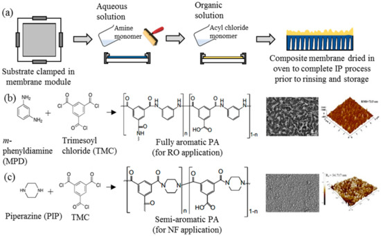
Figure 2.
a
b
c) the two most common crosslinked polyamide (PA) structures for commercial TFC nanofiltration (NF) and reverse osmosis (RO) membranes and their respective FESEM and AFM surface images [40][41].
Figure 2b,c depicts the two commonly used monomers to prepare TFC membranes for the RO and NF process, respectively. The use of different monomers creates different surface morphologies, where the TFC membrane constructed of MPD–TMC generally exhibits a ridge-and-valley structure compared to globular structures in the membrane made of PIP–TMC. Typically, the ridge-and-valley PA layer demonstrates excellent NaCl rejection over the globular PA structure, owing to the high degree of crosslinking that produces dense skin layer [28][42][28,42].
Studies found that an increase in monomer concentration had a positive impact on the TFC membrane performance in terms of water flux and/or salt rejection [54][57][58][54,57,58], but rapidly declined when the concentration exceeded its optimum. It is difficult to precisely pinpoint the ideal concentration of monomers to be used, as there are many factors involved during the polymerization process. These include the choice of additives (e.g., triethylamine and camphorsulfonic acid) in the aqueous/organic phase [14][48][59][14,48,59], the monomer reaction time and temperature [60][61][60,61], properties of organic solvents [62], rinsing and drying conditions [42], as well as the employed IP method [63]. Another point to consider is the property of microporous substrate used, since any variation in its pore size, porosity, hydrophilicity and functional group can profoundly alter the formation of PA layer [31][64][65][66][31,64,65,66]. However, a comprehensive review of the substrate’s effect is beyond the scope of this current paper and readers are advised to refer to [67][68][67,68].
Although the conventional IP technique is the preferred technique to prepare commercial TFC-NF and -RO membranes, it is not without any drawbacks. For instance, the preparation of an extremely thin PA layer (e.g., <50 nm) which effectively removes ions remains a challenge [69][70][71][69,70,71]. Reducing selective layer thickness is critical for high water permeability of membranes and to minimize system footprint for industrial application. Another drawback of conventional IP technique is the use of either rubber roller or airgun to remove excess amine solution from the substrate. Both methods, unfortunately, negatively affect the preparation of TFC/TFN membranes in different ways, and the issues are detailed out in following subsection.
3. Issues with Conventional Interfacial Polymerization Technique
Due to limitations in the current conventional IP technique that complicate the fabrication of better TFC/TFN membranes, the technique is consistently being modified to improve its performance. This is for better control of the PA formation independent of chemicals (e.g., presence of additives and/or different monomer concentrations) and thermal influence (e.g., reaction temperature and/or post-treatment parameters). The first issue with the conventional IP technique is the rubber rolling removal step that causes the amine monomer to be expelled along with the excess aqueous solution. Rubber rolling is compulsory to prevent the formation of extremely small water droplets on the substrate surface prior to the introduction of acyl chloride monomer. Without proper rolling, acyl chloride monomer would react with the water droplets (instead of amine monomer), causing lower degree of PA crosslinking and surface defects. The same method also interferes with the homogenous dispersion of nanomaterials in the PA layer during TFN membrane fabrication. This is because nanomaterials dispersed in the amine-contained aqueous solution are also removed by rubber rolling, hence affecting their distribution and, thus forming agglomeration/voids in the PA layer. Figure 3 presents SEM surface images of the TFN membranes in which nanoparticles were embedded within PA layer via conventional IP technique [48][72][48,72]. Although some studies reported that surface functionalization of the nanomaterials can reduce their agglomeration [49][52][49,52], the rubber rolling step remains the cause for the loss of precious nanomaterials during the fabrication process.
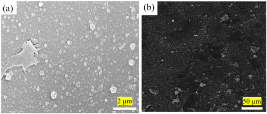
Figure 3. (a) SEM images showing agglomeration of modified-graphene oxide (GO) [48] and (b) multi-walled carbon nanotubes (MWCNTs) [72] in the PA layer of membrane.
Conventional IP process to fabricate TFC/TFN membranes also requires large quantities of organic solvents and monomers to complete film polymerization. It is the second issue plaguing this technique since excess chemicals are not reusable unless post-treatment is performed to recover them. Moreover, the seemingly low quantities of solvents and chemicals to form the crosslinked PA for a lab-scale study becomes economically unviable and non-eco-friendly at the industrial-manufacturing scale. Hence, efforts to modify conventional IP technique should also focus on minimizing chemical use. Figure 4 shows the chronological development of novel/modified IP techniques developed since 2013 for the fabrication of TFC/TFN membranes for water applications. Advancement in IP can potentially improve the intrinsic characteristics of the PA layer while offering more sustainable and environmentally friendly solutions [73].
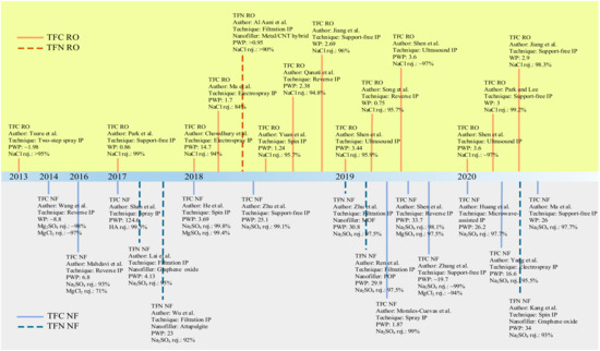
Figure 4. Chronological development of novel IP techniques for pressure-driven water-treatment processes. Permeability is in L/m2·h·bar unit.
4. Technical Challenges of New or Modified IP Techniques
Table 1 details the advantages and disadvantages of each IP technique, based on the thorough review on the new or modified IP techniques to fabricate TFC/TFN membrane in the previous section. Although the support-free IP technique such as DSC and IFIP are highly scalable, the main challenge lies in the transfer of fragile PA layer onto the substrate. In addition, this technique produces membranes with low interfacial stability due to the absence of mechanical interlocking between the substrate and the PA layer. To overcome this, it was suggested to use vacuum filtration/suction to enhance the interfacial adhesion of the PA layer [74][82]. However, the integration of both techniques might result in a low scalability of the overall technique especially in the final vacuum filtration step.
Table 1.
|
Technique |
Advantages |
Disadvantages |
|
Support-free IP |
- High scalability (DSC and IFIP) - High precision (automated DSC and IFIP) - Able to form PA at very low monomer concentration
|
- Difficult to transfer/attach PA film onto substrate
|
|
Filtration-based IP |
- Suitable to deposit 2D nanosheets on the substrate - No leaching of nanomaterials during filtration - Nanomaterials can be well embedded within PA layer with good stability |
- Not suitable for depositing 3D nanomaterials with particle size much smaller than substrate pore size - Precise control of PA layer thickness is rather difficult - Low scalability
|
|
Spin-based IP |
- Rapid process - Able to produce highly uniform PA layer |
- Low scalability - Chemical/nanomaterials wastage is unavoidable during spinning - Require precise control of shearing force
|
|
Ultrasound-based IP
|
-Formation of nanovoids within PA layer that could improve water flux |
- Limited studies
|
|
Spray-based IP |
- High scalability - Minimum use of chemicals/nanomaterials - Relatively fast process - Precise control of PA layer thickness
|
- Lack of long-term membrane stability evaluation - Lack of economic analysis |
|
Electrospray-based IP |
- Moderate scalability - Minimum use of chemicals - Precise control of PA layer thickness (at nm scale)
|
- Slow process (>1 h) - Relatively high energy requirement (high voltage equipment) - Difficult to produce large-sheet of membrane
|
|
Reverse IP |
- Suitable for hydrophobic substrate |
- Difficult to form defect-free TFC membrane, using widely used substrate (e.g., PSf and PAN)
|
Despite exhibiting promising results in depositing 2D nanomaterial, filtration-based IP is unsuitable for the deposition of 3D nanomaterials; especially those that are smaller than the substrate pores (typically with molecular weight cutoff (MWCO) of 30–50 kDa [58]). The vacuum filtration may result in an extremely low or total absence of nanomaterials on the PA layer, as they could be filtered out or trapped within substrate pores. As a consequence, the effectiveness of such TFN membranes may be reduced. Both filtration- and spin-based IP are not easy to be scaled up as the commercially available machines are unable to handle large size of typical membrane sheet required (1 m in length) to form spiral wound membrane module. Compared to other novel IP technique, spin-based IP has another major problem, i.e., inevitable wastage of chemical and nanomaterial during spinning process. This method may face difficulties in mass production.
For ultrasound-based IP, only limited studies were documented in the literature. As this technique is relatively new, there is limited understanding on its fundamental knowledge. Spray-based IP meanwhile, is more competitive and can be readily integrated with existing membrane manufacturing lines, as long as long-term membrane stability and economic analysis have been carried out. Similarly, while electrospray-based IP demonstrates high potential in membrane fabrication due to its minimum use of chemicals and the precise control of PA thickness, this approach is quite time consuming (>1 h is needed to develop PA layer [75][128]). The use of high voltage equipment also warrants a high energy cost and poses an additional risk factor to the safety of the operators.
On the other hand, the reverse IP procedure may prove to be rather similar to the conventional IP technique, except that the sequences of aqueous and organic solutions are reversed during the IP process. Reverse IP is particularly unsuitable for the fabrication of PA on hydrophilic substrates (e.g., cellulose nanofibers [76][131] and PAN nanofibers [77][132]); as such, pretreatment is required to modify substrate properties. This makes the overall membrane production complex and may incur additional manufacturing costs. Similar to conventional IP, the reverse IP approach also encounters difficulties in controlling the film properties (e.g., PA thickness, roughness, porosity and surface chemistry). This is due to their limiting fabrication procedures that self-terminate (diffusion-limited), leading to an uncontrolled PA growth. Figure 5 compares the PWP and degree of salt rejection of membranes made by novel/modified IP technique with conventionally made commercial NF/RO membranes, while Figure 6 shows the relationship between the membrane salt rejection and its water permeability. As can be seen, the novel/modified IP techniques, in general, can potentially overcome the trade-off effect in the conventional membranes, by further increasing the water permeability, without compromising salt rejection.
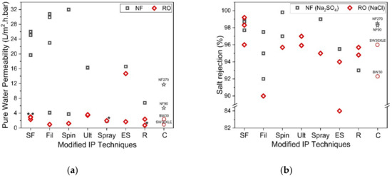
Figure 5.
a) Comparison of membrane permeability fabricated by using support-free IP (SF) [63][78][79][80][74][81], filtration-based IP (Fil) [29][82][83][84][85], spin-based IP (Spin) [30][86][87], ultrasound-based IP (Ult) [88][89], spray-based IP (Spray) [90][91], electrospray-based IP (ES) [31][92][93], reverse IP (R) [94][95][96] and commercial membrane (C) and (
b
2
4
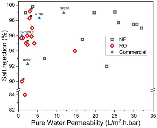
Figure 6. Salt rejection (Na2SO4 for NF and NaCl for RO) and water permeability of membranes made of novel IP techniques. (* Note: The data were obtained from water permeability of 2000 ppm NaCl solution).
