Digital Image Correlation (DIC) is a non-invasive imaging technique that has been used in a significant number of research fields to measure the strain fields across the surface of a body. This entry gives a basic overview of how the DIC method came to be, both in two and three dimensions and some information about the more recent development of DIC in the X-ray spectrum.
- Digital Image Correlation
- Non-Invasive Techniques
- Strain Field Measurements
DIC is a method by which strain fields can be recorded across the surface of object as it deforms, without the need for strain gauges or other contact methods that may interfere with the deformation. This is accomplished by taking digital images of a random, high-contrast speckle pattern on the surface of the object. As the object deforms, the pattern on the surface also deforms and the changes in the pattern can be used to quantify the strain the object undergoes.
The method to carry out digital image correlation was first described in 1983 by Sutton et al [1]. The authors described a method of taking digital images of an object prior to and post deformation and using the generated light intensity levels to convert the discrete data into a continuous form via a surface fit, shown in figure 1. Due to the limits of computer technology in the 1980s, the overall images were broken down into small subsets for processing by the algorithm that the authors describe. The algorithm takes the subsets of the pattern pre-deformation and correlates them to the same subsets in the post-deformation surface. By using the algorithm that the authors describe, Sutton et al. were able to successfully measure beam deflections greater than 0.1 pixels [1[1]].
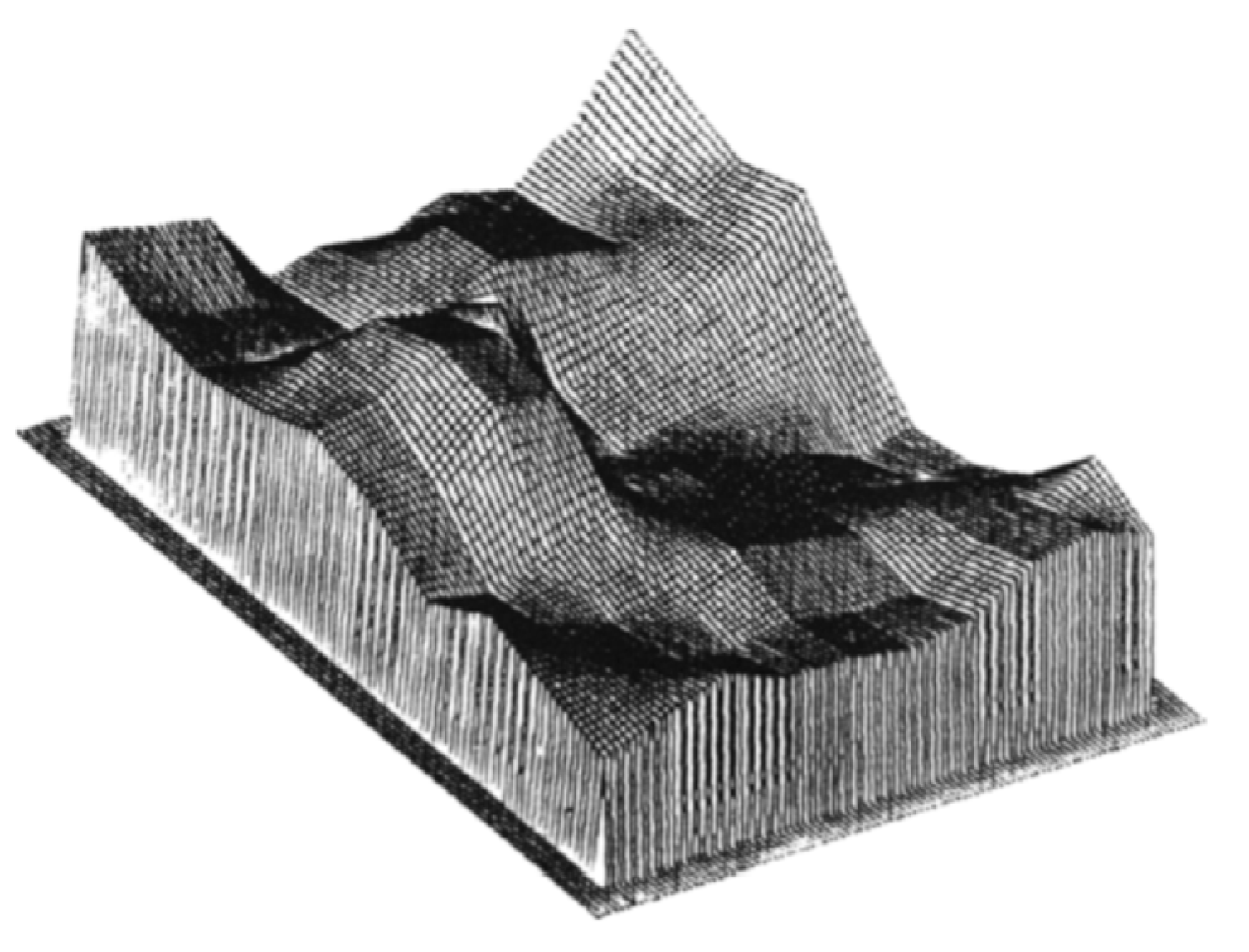
Figure 1. Example of an intensity pattern reconstructed using bilinear interpolation into a continuous form. Reproduced from Sutton et al. [1[1]], with permission from Elsevier.
This method does require a couple of basic assumptions; (i) the pattern deforms exactly as the surface of the pattern, (ii) the light intensity patterns of the pre- and post-deformation surface have a unique one-to-one correspondence with the respective pre- and post-deformation surfaces [2[2]]. In two-dimensional DIC, there is also a requirement that any out-of-plane displacement does not affect the in-plane deformation or displacement of the characteristic intensity surfaces and any derivatives of the out-of-plane displacement are significantly smaller than the derivatives of the in-plane displacements [2[2]]. This is due to the deformation theory, described in [1[1]], demonstrating that the observed intensity pattern is a two-dimensional projection of the object onto a plane [2[2]]. Chu et al. [2[2]] took the algorithm described in [1[1]] and conducted a number of experiments to determine the accuracy of the system in three situations, (i) uniform translation, (ii) rigid body rotation, and (iii) uniform finite-strain test. The authors also compared the use of two different interpolation methods in the conversion of the discrete intensity map from the camera into continuous data; bi-linear and polynomial interpolation. The authors reported that the displacement components were within reasonable accuracy for both interpolation methods for the uniform translation experiments, while the rotation cases only agreed well (less than 4% error) for cases below 6 degrees of rotation. The last test the authors reported on found that the results for the uniform finite-strain test were very dependent on the image resolution, with large image resolution giving results between −18% to 8%, but lower resolutions giving up to −136% error [2[2]].
In order to increase the accuracy of the DIC method, Bruck et al. [3[3]] explored, using the Newton–Raphson method of partial differential corrections to increase the accuracy of displacement and gradient calculation. The Newton–Raphson method is based on the calculation of correction terms that improve the initial guesses of the DIC algorithm. By using the displacement of the subset centre, estimated to within one pixel, the algorithm is less likely to find a local minimum and more likely to find the absolute minimum. The authors also found that the Newton–Raphson method reduced computational time, when compared to the previously described coarse-fine search method. To evaluate the accuracy of the Newton–Raphson method in predicting displacement and gradient terms, the authors used three cases: (i) no deformation, (ii) translation only, and (iii) rotation only [3[3]].
The first case of no deformation was undertaken, to determine the minimum error that could be expected in the system, and this is now part of the standard procedure of DIC [4[4]]. The second experiment consisted of translations of 500 µm with a resolution of 87 pixels per cm (giving each translation at approximately 0.044 pixels) and the authors show good agreement between the actual and DIC results [3[3]]. The third experiment the authors tried was rotation only, with ten rotations of 0.0157 radians, with two different subset sizes (50 × 50 and 20 × 20 pixels). In this case, the authors reported that larger subset size gave an order of magnitude improvement in the standard deviation for the predicted results [3[3]].
As the technique advanced, methods were described to increase the accuracy of displacement and gradient calculations in digital image correlation. Sjödahl and Benckert [5[5]] described a more robust algorithm when it is subjected to decorrelation and displacement gradients. The idea of the new technique is to cross-correlate sub-images digitally from two similar, but relatively displaced, speckle patterns and apply a maximum search routine near the correlation peak, in order to obtain sub-pixel accuracy. While the authors concede that the formula the authors present is more time consuming, it can be performed in the spectral domain, through the use of a Fourier transform, and is significantly faster in the spectral domain. The authors demonstrate that to obtain a greater than 80% success rate of their algorithm, the sub-image size should be at least 10 times the speckle size [5[5]].
By adding a second camera and turning the imaging system into stereo, out-of-plane displacements can be quantified, allowing for an accurate measurement of the three-dimensional strain of the object surface. Synnergren and Sjödahl [6[6]] were the first to describe a three-dimensional DIC (3D DIC) technique and a calibration algorithm for such a system. The authors describe a physical model that relates points on an object with corresponding points in an image of that object. The shape of the object is measured by the cross-correlation of several sub-images from the two camera images, shown in figure 2, through the algorithm described by Synnergren and Sjödahl. The two cameras are oriented so that the optical lenses are in parallel. This means that each camera can view the same image as the other camera, by moving the camera perpendicular to its optical access. The difference in the image fields is predominantly due to the shape of the object, and in order to reconstruct the shape of the object, the system must be calibrated. The calibration routine should be (i) easy to use, (ii) with a calibration target that is easy to make, and (iii) it should give accurate results. Synnergren and Sjödahl suggest a flat plate covered with a random dot pattern, that can move only in the z-direction (towards or away from the cameras), would satisfy the second requirement. The second calibration step would be to perform reference movements of the calibration plates. This is accomplished by moving the plate a known distance away from or towards the cameras and taking two sets of images, one before and one after the movement. The apparent movement due to the physical movement of the calibration plate is calculated for each camera. A least-squares optimization is then used to cross-correlate the apparent movement in one image, with the corresponding image from the other camera. To determine the accuracy of their 3D DIC method, Synnergren and Sjödahl performed the rigid body translation of a small model car and rotation of a suspended cylinder. For the rigid body motion, the authors reported that the main source of error in the rigid body motion was random error, with no significant influences originating from misalignment, distortion of the lenses or compensation for the shape of the object [6[6]]. For the rotation of the suspended cylinder, the standard deviation of the rig the authors used was in the order of 0.15 milliradians. In comparison, the authors reported the algorithm and procedure accurately, predicting the rotation of the cylinder with between 0.13 to 0.17 milliradian standard deviation. The random errors were reported to be in the order of 1/100 of the pixel size used in the real experiments for the in-plane components and the out-of-plane errors were about six times lower [6[6]].
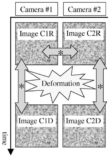
Figure 2. Time sequence, the arrows with * show which images are cross-correlated to find the 3D displacement field. Reproduced from Synnergren and Sjödahl [6[6]], with permission from Elsevier.
As high-speed camera technology has advanced, 3D DIC has been extended to measure material deformation in areas where the strain rate can be quite high (in the order of 104 /s). In order to perform high-speed (10,000+ frames per second, FPS) and ultra-high-speed (>1M frames per second) 3D DIC, several considerations need to be taken into account. The first of these factors is exposure time; limits in exposure time can cause blur, which lowers the algorithms’ ability to attain sub-pixel accuracy [7[7]]. The next factor is image quality, which is measured as high contrast and low noise. Very high levels of image contrast can be difficult to attain, as extremely short exposure times require high levels of scene illumination. A lack of contrast due to poor lighting can reduce the effective grayscale range of the image from 12-bits to 3- or 4-bits. Large amounts of lighting can be achieved with halogen lamps, but the heat from these light sources needs to be managed. Advances in LED lighting technology have allowed for bright lights that do not add significant heat to the sample. In terms of noise, this is usually related to the specific cameras, with some ultra-high-speed cameras having image intensifiers, which add noise. Noise of the system can be measured by the use of a speckled plate with images taken of the plate, while stationary and undergoing rigid body motion. Understanding how the cameras achieve the high and ultra-high frame rates is also important. Some ultra-high-speed cameras utilize a rotating mirror to project the image onto multiple sensors. This technique can cause large misalignments in 3D DIC, due to the different optical pathways each image travels, and this makes cameras of this design unsuitable for 3D DIC. In addition, understanding the optical components, such as beam splitters, image intensifiers, and fibre optic bundles tying the intensifiers to the charge coupled device (CCD), and how the authors can cause a number of measurement uncertainties, such as variability blurring and non-radial distortions, can be very important [7[7]]. While some have managed to develop a correction scheme to remove the complex distortion field in a 3D DIC setup, the variability of the displacement was ten times larger and the strain twenty times larger than a comparable high-speed complimentary metal-oxide semiconductor (CMOS) camera, even without the sample being moved [8[8]]. Another major factor in using 3D DIC for high-strain rate events is ensuring that the paint and speckle pattern remains adhered to the deforming surface and are representative of the surface deformation [7[7]].
With advances in digital x-ray camera technology, more research has been done on capturing multi-frame sequences with x-ray DIC. Jones et al. [9[9]] performed a study comparing the errors in an optical 3D DIC system to an x-ray 3D DIC system, in situations where the optical system is known to operate poorly, such as imaging through distortions in the air caused by heat. To begin with, the authors performed a study, looking at methods of applying a speckle pattern with a denser material than the object of interest (in their case, an aluminium plate). The authors also examined the effect of plate thickness to speckle thickness to control contrast. The material the authors used for the x-ray speckle pattern was a thermally sprayed Tantalum powder with an aluminium mask to generate the speckle pattern. The authors used a thin adhesive layer to put the same speckle pattern for the optical cameras over the x-ray speckle pattern. While the two x-ray cameras (Varex 2520DX, Varex Imaging, Salt Lake City, Utah, USA) and the two optical cameras (PointGrey Grasshopper, FLIR Systems, Inc., Wilsonville, Oregon, USA) only ran at about five frames per second, the principles of x-ray speckle generation and the advantages shown are valid for higher frame rate x-ray photography. Both the optical and x-ray stereo systems were calibrated independently using the VIC-3D software (Correlated Solutions, Inc., Irmo, SC, USA). The authors conducted two experiments to compare the two systems, (i) pure translation of the speckle plate, and (ii) a stationary target, but with a hot plate in front of the target to cause optical distortions. For the first test, their results show that both the optical and x-ray systems were in good agreement, for both the in-plane and out-of-plane translations, and had similar noise floors. The results for the second experiment that the authors conducted showed significant displacements with the optical system, even though the sample was not moving. In contrast, the x-ray system recorded only the random noise floor. The errors in the optical system recording displacement through heat distortions were 5–18 higher than the error of the x-ray system. The optical system also measured errors of 2–3 times higher in the strain measurements. This shows that x-ray 3D DIC could be a valuable tool in future to measure displacement and strain in regions, that are either not accessible via optical means, or are optically obscured [9[9]].
One issue that can become pertinent in the use of 3D DIC is the resolving of different scales of phenomenon. Given the finite resolution of high and ultra-high-speed cameras, resolving the strain field for small scale localized deformation events can be at odds with determining the overall global strain field of the object being examined. An example of this is Patel and Peralta [10[10]], where the authors examine the evolution of microbuckling in an UHMWPE laminate beam, using 2D DIC and the ARAMIS DIC software (GOM GmbH, Braunschweig, Germany), with a supported length of 152 mm. In comparison, the scale of the microbuckling is in the order of 600 µm [10[10]]. Patel and Peralta [10[10]] used a 100 µm thickness adhesive transfer tape and copper microparticles to generate a speckle pattern with a mean dot size of 15–20 µm and an inter-dot spacing of less than 10 µm. Applying a speckle pattern on a scale that can measure this microbuckling, but also being able to determine global strains can be challenging, especially when examined in three dimensions. Resolving these different scales of phenomenon requires the careful choice of field of view, an increased depth of field and a reliable speckle pattern that will still represent the underlying material deformation during large shear.
References
- Sutton, M.A.; Wolters, W.J.; Peters, W.H.; Ranson, W.F.; McNeill, S.R.; Determination of displacements using an improved digital correlation method. Image Vision Comput. 1983, 1, 133–139.
- Tsuchin Chu; W. F. Ranson; M. A. Sutton; Applications of digital-image-correlation techniques to experimental mechanics. Experimental Mechanics 1985, 25, 232-244, 10.1007/bf02325092.
- Hugh Bruck; S. R. McNeill; M. A. Sutton; W. H. Peters; Digital image correlation using Newton-Raphson method of partial differential correction. Experimental Mechanics 1989, 29, 261-267, 10.1007/bf02321405.
- Sutton, M.A.; Orteu, J.J.; Schreier, H. Image Correlation for Shape, Motion and Deformation Measurements: Basic Concepts, Theory and Applications; Springer: Boston, MA, USA, 2009; Volume 1.
- M Sjödahl; L R Benckert; Electronic speckle photography: analysis of an algorithm giving the displacement with subpixel accuracy.. Applied Optics 1993, 32, 2278–2284.
- Per Synnergren; Mikael Sjödahl; A stereoscopic digital speckle photography system for 3-D displacement field measurements. Optics and Lasers in Engineering 1999, 31, 425-443, 10.1016/s0143-8166(99)00040-8.
- P L Reu; T J Miller; The application of high-speed digital image correlation. The Journal of Strain Analysis for Engineering Design 2008, 43, 673-688, 10.1243/03093247jsa414.
- H. W. Schreier; D. García; M. A. Sutton; Advances in Light Microscope Stereo Vision. Experimental Mechanics 2004, 44, 278-288, 10.1177/0014485104041546.
- E.M.C. Jones; E.C. Quintana; P.L. Reu; J.L. Wagner; X-Ray Stereo Digital Image Correlation. Experimental Techniques 2019, 44, 159-174, 10.1007/s40799-019-00339-7.
- Patel, J.; Peralta, P. Mechanisms for kink band evolution in polymer matrix composites: A Digital Image Correlation and Finite Element study. In Proceedings of the ASME 2016 International Mechanical Engineering Congress and Exposition, Phoenix, AZ, USA, 11–17 November 2016; The American Society of Mechanical Engineers: New York, NY, USA, 2017.