Optical coherence tomography (OCT) enables three-dimensional imaging with resolution on the micrometer scale. The technique relies on the time-of-flight gated detection of light scattered from a sample and has received enormous interest in applications as versatile as non-destructive testing, metrology and non-invasive medical diagnostics. However, in strongly scattering media such as biological tissue, the penetration depth and imaging resolution are limited. Combining OCT imaging with wavefront shaping approaches significantly leverages the capabilities of the technique by controlling the scattered light field through manipulation of the field incident on the sample.
- optical coherence tomography
- wavefront shaping
- biomedical imaging
- turbid (scattering) media
Note: The following contents are extract from your paper. The entry will be online only after author check and submit it.
1. Introduction
Optical coherence tomography (OCT) is closely related to white light and low coherence interferometry as well as to optical coherence domain reflectometry which was originally developed to locate defects in optical fibers [1][2] [1,2] and soon proved to be feasible for biomedical imaging [3][4][3,4]. The group of Fujimoto presented the first OCT system for the imaging of ex-vivo biological tissue in 1991 [5]. The first in-vivo imaging applications were reported in 1993 independently by Fercher et al. [6] and by Swanson et al. [7]. Here, we restrict ourselves to a brief description of the main OCT concepts as required for a proper understanding of the wavefront shaping implementations. For a detailed discussion, we refer to the references, as indicated at the appropriate positions in the text.
OCT is based on the interference of broadband light, which allows one to determine the time-of-flight or the optical path length distribution of the electromagnetic wave reflected at a sample. Typically, OCT systems use point-wise sample illumination, i.e., the beam is focused at the sample similar to confocal microscopy. The reflected beam is collected by the imaging optics and superimposed with a static reference beam which has a well-known optical path length.
The principle of optical coherence tomography is well-understood by considering a Michelson interferometer with the sample placed in one interferometer arm (Figure 1). The approach represents one important class of OCT systems, namely time domain OCT (TD-OCT).
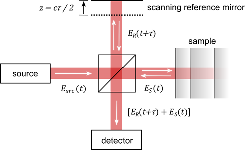
Figure 1. Principle of optical coherence tomography. The technique is comparable to a Michelson interferometer with the sample placed at one interferometer arm. Scanning the length of the reference arm allows one to determine the time-of-flight of the beam which is backscattered from the sample. Variables are as in the text. Image from [8], with permission.
2. Principles of Wavefront Shaping
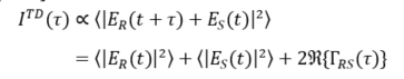
The beam incident in the interferometer is described by its electric field Esrc, which is coupled to the magnetic field through Maxwell’s equations. The incident field Esrc is divided at the beam splitter, reflected at the two interferometer arms, recombined and detected. The field in the plane of the detector, thus, reads ER(t) + ES(t), where ER describes the field returned from the reference arm and ES the field returned from the sample. Displacing the reference mirror by the distance z increases the length of the reference arm and introduces an additional temporal delay τ = 2 z/c to the reflected reference beam where c is the speed of light. At the detector, the intensity of the superimposed beams of a TD-OCT setup ITD reads [9][10][11][12] [9–12]:
 |
(1) |
Here, ER and ES stand for the field returned from the reference and sample arm, respectively, t denotes the time, τ the above temporal delay, the brackets stand for the time averaged values and for the real-part of the cross-correlation term (see below). The first two terms in the second line of Equation (1) correspond to the intensity returned from the reference and sample beam, respectively. The third term yields the interference of the two beams and describes the real part of the field cross-correlation , which is also termed cross coherence or mutual coherence function [13] [9,10,13] (* denotes the complex conjugated quantity). Thus, TD-OCT essentially captures the intensity of the superimposed reference and sample beam at a point detector while scanning the length z or the temporal delay at the reference beam. A full scan yields a single depth scan, also known as A-scan, at the point at which the sample is illuminated. Laterally scanning the sample beam in one direction yields a cross-sectional image perpendicular to the sample surface, i.e., a B-scan, while additional scanning the second lateral direction yields a C-Scan, i.e., a volumetric (3D) image. Most practical OCT systems are based on fiber-optic interferometers. A set of scanning mirrors allows one to scan the sample beam laterally to enable cross-sectional and volumetric imaging.
An important aspect is the depth of field (DOF) which describes the axial range at which the sample beam remains tightly focused. The DOF depends on the Rayleigh length of the sample beam and, hence, becomes smaller in case the sample beam is more tightly focused. With most OCT systems, low NA objective lenses are used to achieve a large DOF. Axial imaging is performed by scanning the reference mirror over distances of several millimetres. A large DOF, hence, is required to maintain a comparable lateral resolution and sensitivity at the full axial field of view (FOV) of the OCT system. In case a low NA objective lens is used, the impact of the imaging optics on the axial sensitivity of the OCT system can be neglected. With regard to resolution, in contrast to conventional optical imaging approaches, the lateral and axial resolution of OCT systems can be tuned independently.
TD-OCT systems acquire the cross-correlation by scanning the length (or the temporal delay) of the reference beam and by capturing the intensity of the superimposed fields with a scalar detector. The field cross-correlation closely relates to the power spectral density of the superimposed beams. A signal which is equivalent to the TD-OCT A-scan hence can be calculated from the spectrum without mechanically scanning the reference arm, as well. Two different approaches are established to acquire the power spectral density for OCT imaging practically. Spectral domain optical coherence tomography (SD-OCT) systems utilize broadband light sources, which are used for TD-OCT systems as well, and replace the scalar detector of the TD-OCT system with an imaging spectrograph consisting of a spectrometer and a high-speed camera. A single camera frame yields a full spectrum from which the A-scan signal is calculated. High-speed and high-sensitivity cameras are required to enable high A-scan rates, though. In an alternative approach termed swept source optical coherence tomography (SS-OCT), the spectral raw data can be acquired sequentially by using a wavelength scanning laser and a scalar detector such as a photodiode. A single wavelength sweep yields the raw spectral data which is used to calculate the A-scan. SS-OCT systems allow one to use high-sensitivity scalar (point) detectors as well as laser sources which feature a high instantaneous power. High-speed wavelength scanning sources are required to achieve frame rates which are sufficiently fast for real-time OCT imaging. Data processing is similar for SD-OCT and SS-OCT systems. Both techniques calculate the time-domain A-scan signal from the inverse Fourier transform of the spectral raw data and, hence, are described by the more general term Fourier domain optical coherence tomography (FD-OCT). FD-OCT approaches were largely unnoticed, however, until three independent groups demonstrated the technique to yield a superior signal-to-noise (SNR) compared to TD-OCT systems in 2003 [14][15][16][14–16]. This discovery triggered a push in OCT development and resulted in most contemporary OCT systems to be based on Fourier domain techniques.