Negative temperature coefficient (NTC) materials are usually based on ceramic semiconductors, and electrons are involved in their transport mechanism. A new type of NTC material, adequate for alternating current (AC) applications, is represented by zeolites. Indeed, zeolites are single charge carrier ionic conductors with a temperature-dependent electrical conductivity. In particular, electrical transport in zeolites is due to the monovalent charge-balancing cations, like K+, capable of hopping between negatively charged sites in the aluminosilicate framework. Owing to the highly non-linear electrical behavior of the traditional electronic NTC materials, the possibility to have alternative types of materials, showing linearity in their electrical behavior, is very desirable. Among different zeolites, natural clinoptilolite has been selected for investigating NTC behavior since it is characterized by high zeolite content, a convenient Si/Al atomic ratio, good mechanical strength due to its compact microstructure, and low toxicity. Clinoptilolite has shown a rapid and quite reversible impedance change under heating, characterized by a linear dependence on temperature.
- NTC material
- Ionic conduction
- Zeolite
- Clinoptilolite
1. Zeolite Structure
Zeolites are ceramics with a hybrid ionic-covalent structure and, owing to the crystalline lattice particularly reach in cavities, they are lightweight materials. The crystalline lattice of zeolites consists of a three-dimensional aluminosilicate network composed of SiO4 and AlO4 tetrahedra connected together by the oxygen atoms[1][2]. Since negative charges are present in the aluminosilicate framework, extra-framework cations are required for the material electroneutrality condition. Monovalent metal cations are located close to the aluminum atoms in order to balance their negative charges, while bivalent metal cations are positioned halfway between two neighboring negatively charged sites. In particular, the extra-framework ions, typically present in nature-made zeolites, are alkali (K+, Na+) and alkaline-earth (Ca2+, Mg2+) metal cations. Since mineral zeolites have mostly aluminous nature, i.e., they are characterized by a low value of the Si/Al ratio, which usually ranges from 4 to 7, a large amount of charge-balancing metal cations is contained. Many natural zeolites also contain iron, which causes a reddish coloration of the mineral. Iron can be present both in the covalent framework (isomorph substitution of silicon, like in the aluminum case) and/or in the extra-framework, as charge-balancing cations (ferric cations, Fe3+).
Zeolites are microporous crystalline materials due to the presence of large and small reticular cavities (α and β cages, respectively). These cages are connected to each other to form regular arrays of channels. As visible in Figure 1, the silica and alumina tetrahedra, connected together by shared oxygen atoms, give rise in a very common zeolite type named clinoptilolite to three types of channels that are organized in form of a two-dimensional array. In particular, the A-type (openings: 3.1–7.5 Å) and B-type (openings: 3.6–4.6 Å) channels are parallel to each other and parallel to the c-axis, while the C-type channels (openings: 2.8–4.7 Å), which are parallel to the a-axis, perpendicularly intersect the A and B channels.
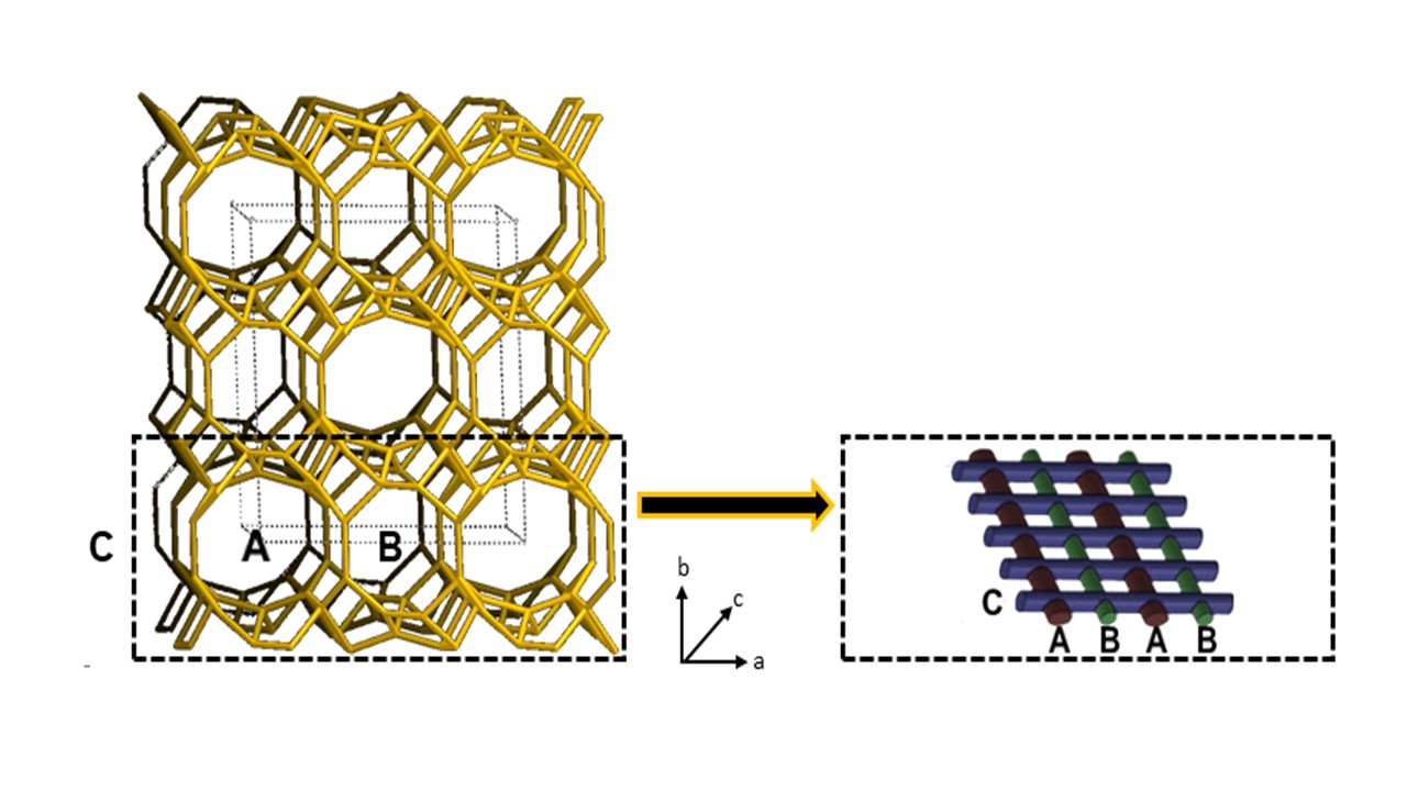
Figure 1. Schematic representation of the channels structure in clinoptilolite crystals.
Extra-framework cations and adsorbed water molecules are located inside these channels, both close to the aluminum atoms. Owing to the strong electrostatic interaction (Coulomb’s forces) acting between the extra-framework cations and the negatively charged aluminum atoms, cations practically do not move under the effect of an electric field at room temperature. Actually, the negative charge is not wholly localized on the aluminum atoms, but it is spread by the mesomeric effect on a ‘nucleophilic area’, including the aluminum atom and the four neighboring oxygen atoms. Differently, at high temperatures, cations with a low charge density (i.e., K+ or Na+) have enough energy for hopping among neighboring empty nucleophilic areas. Empty nucleophilic areas are contained in the zeolite framework because of the bivalent cations, the presence of which leaves a number of locally unbalanced negative sites in the covalent crystal. Such electric behaviour of zeolite is potentially useful for a number of devices activated by temperature (e.g., thermal switches, thermistors, temperature sensors, etc.).
2. Electrical Conductivity of Zeolite
2.1. Vučelić Conduction Model
Zeolites have unique physical properties resulting from their unusual chemical structure. Vučelić defined the extraordinary crystalline structure of zeolite as a ‘reverse’ metallic lattice[3]. According to the electrical conduction model proposed by Vučelić in 1977[4][5], only those extra-framework charges capable of moving in the ‘free ionic conduction zones’, i.e., the free cationic conduction bands located exactly in the middle of crystal channels, can promote electrical transport trough the ceramic material. Indeed, ions at the centers of cavities are effective carriers of current since they move through the zeolite crystal with only minimal activation energy. This interesting model proposed by Vučelić constitutes an analogous depiction of the behavior of electrons in a fixed cationic electromagnetic field and their electrical conduction mechanism. Therefore, Vučelić has conformed zeolites to the commonly adopted representation of electrical transport in metallic crystal structures.
2.2 Theoretical Treatment
The electrical properties of zeolites mainly depend on the contained monovalent metal ions (Me+) because they are less strongly held by the negatively charged lattice and can easily migrate between two neighboring negative sites through the free ionic conduction zones. More generally, the electrical conductivity of clinoptilolite, σ(T), depends on the following three factors: (i) charge of the electrical carriers: Ze−, where e− is the elementary charge (e− = 1.602 10−19 C); (ii) concentration of the electrical carriers: [MeZ+]; and (iii) mobility of the electrical carriers: μ, according to the following physical law: σ(T) = Σi[Zi∙e−∙[Mez+]i∙μi], where the sum is formally extended to all extra-framework cations present in the substance. However, for a clinoptilolite-K,Ca sample, potassium ions located in the super-cages are almost exclusively involved in the migration under an applied sinusoidal field. Indeed, the contribution of Ca2+ cations is negligible because they have an electrical charge larger than K+ and are present in the clinoptilolite sample at a lower concentration. In addition, iron does not participate in the electrical transport mechanism because it is mostly located in the framework, isomorphous substitution, just like in the case of aluminum atoms, while its ionic form (Fe3+) has a very large electrical charge and stably adheres to the crystal framework. Finally, it is possible to approximately write:
σ(T)=e-·[K+]*·μK+
where [K+]* is the molar concentration of the excited K+ cations present in the system at T temperature. Each K+ ion is located in a potential well (the ‘nucleophilic area’), the walls of which are represented by the four negatively charged oxygen atoms located close to the aluminum atom. The concentration of excited K+ present at a zeolite cage/channel center is a temperature-dependent quantity; indeed, [K+]* increases with increasing temperature, thus determining an increase in the zeolite electrical conductivity. In particular, the dependence of [K+]* on temperature is given by the following expression:
[K+]* =[K+]tot/(1+exp(ΔG°/RT))
This relationship has been obtained by assuming that the potassium cations present in the free ionic conduction band (i.e., the excited potassium cations, (K+)*, present at the center of channels), are in dynamic equilibrium with the potassium cations located outside this band (i.e., non-excited potassium cations, K+, present on the channel walls). The equilibrium constant, Keq, for this excitation process is the ratio between the specific rate (i.e., the kinetic constants) of the direct (i.e., excitation, K+→(K+)*) and indirect (i.e., relaxation, (K+)*→K+) elemental processes (Keq=k1/k-1). This quantity depends on temperature according to the following relationship: keq=[K+]*/[K+]=exp(-ΔG°/RT), where T is the absolute temperature, R the universal gas constant, and ΔG° is the standard free-energy variation in the K+ excitation process. In this relationship, ΔG° corresponds exactly to the activation energy, Ea, for the excited potassium cation formation; indeed, since ΔS°=0 because the cation excitation process does not involve any entropy variation, it is possible to write: ΔG° = ΔH°-T·ΔS° = ΔH° = H°(K+*)-H°(K+) = Ea. The above equation can be approximate by the quantity: [K+]tot·exp(-Ea/RT) and therefore the logarithm of the zeolite electrical conductivity, ln(σ), is directly proportional to 1/T, as it has been experimentally found [3-5].
2.3 Electrical measurement method
Zeolites like clinoptilolite have electrical impedance values of the MΩ magnitude order. This quite high electrical impedance value can be measured by the 'voltamperometric method', which is based on a specific set-up that uses the following very common electronic equipments: a function generator (FG) or an arbitrary waveform generator (AWG), to be used as sinusoidal voltage source; a wide-band true-RMS AC voltmeter, to measure the voltage applied to the sample; and a wide-band true-RMS AC micro-ammeter, to measure the current intensity moving in the sample. Function generator and voltmeter are electrically connected in parallel with the sample, while the micro-ammeter is connected in series with the sample. The most adequate FG are those based on direct digital synthesis (DDS), because these electronic equipments are capable to generate a high precision sigmoid signal. Examples of this instrument type are: the ATF20B+ (Gratten) and SFG-1013 (GW Instek). AC voltmeter and micro-ammeter must have a bandwidth of 100kHz (or at least 10kHz). In addition, for accurate measurements, the voltmeter internal resistance should be as high as possible (at least 10MΩ) and micro-ammeter internal resistance as low as possible (i.e., few ohms). Examples of this instrument type are: the BM869s (Brymen) and UT171B (UNI-Trend). Nano-ammeters and pico-ammeters could be even more convenient that a micro-ammeter for the higher sensitivity of the measurement they are capable to perform. In addition to the impedance value, such simple measurement method allows to obtain the sample I-V characteristics (useful to investigate the electrical transport mechanism), electrical impedance spectrum, Z-T behaviour (like it has been used in this study), etc. Alternatively, the zeolite impedance could be determined by a LCR-meter, which allows measurements at some frequency values. The same experimental set-up can be used also to perform time-resolved electrical measurements (see Figure 2), that are useful for studying ‘temporarily evolving’ phenomena (e.g., the sample electrical response to a thermal pulse). In this case, usually the intensity, I, of the current moving through the sample, under an applied constant voltage value, is measured as a function of time. Since the applied voltage value is known and it results practically a constant for the highly resistive zeolite samples, the impedance (Z=V/I) temporal evolution can be readily calculated from the measured current intensity values. Electrical measurements are recorded vs. time by using the DMM internal datalogger. Frequently, the DMM datalogging system needs to be connected to a PC by a cable through an optical port. This PC optical insulation from DMM is required to prevent its damage. In the case of very rapid physical phenomena (e.g., a fast thermal heating of the sample, like in our case), the DMM datalogger should offer a high enough sampling rate (e.g. 5-10 Sa./s) to conveniently record the phenomenon.
The testing frequency has been selected on the basis of the clinoptilolite electrical impedance spectrum, shown in Figure 2. As visible, the clinoptilolite Z value decreases rapidly with increasing of frequency (according to a sigmoid curve); however, the Z value can be considered approximately as a constant at frequency values above 1kHz. In particular, a frequency value of 5kHz has been selected for all time-resolved current intensity measurements.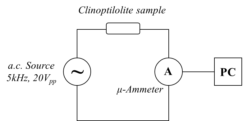
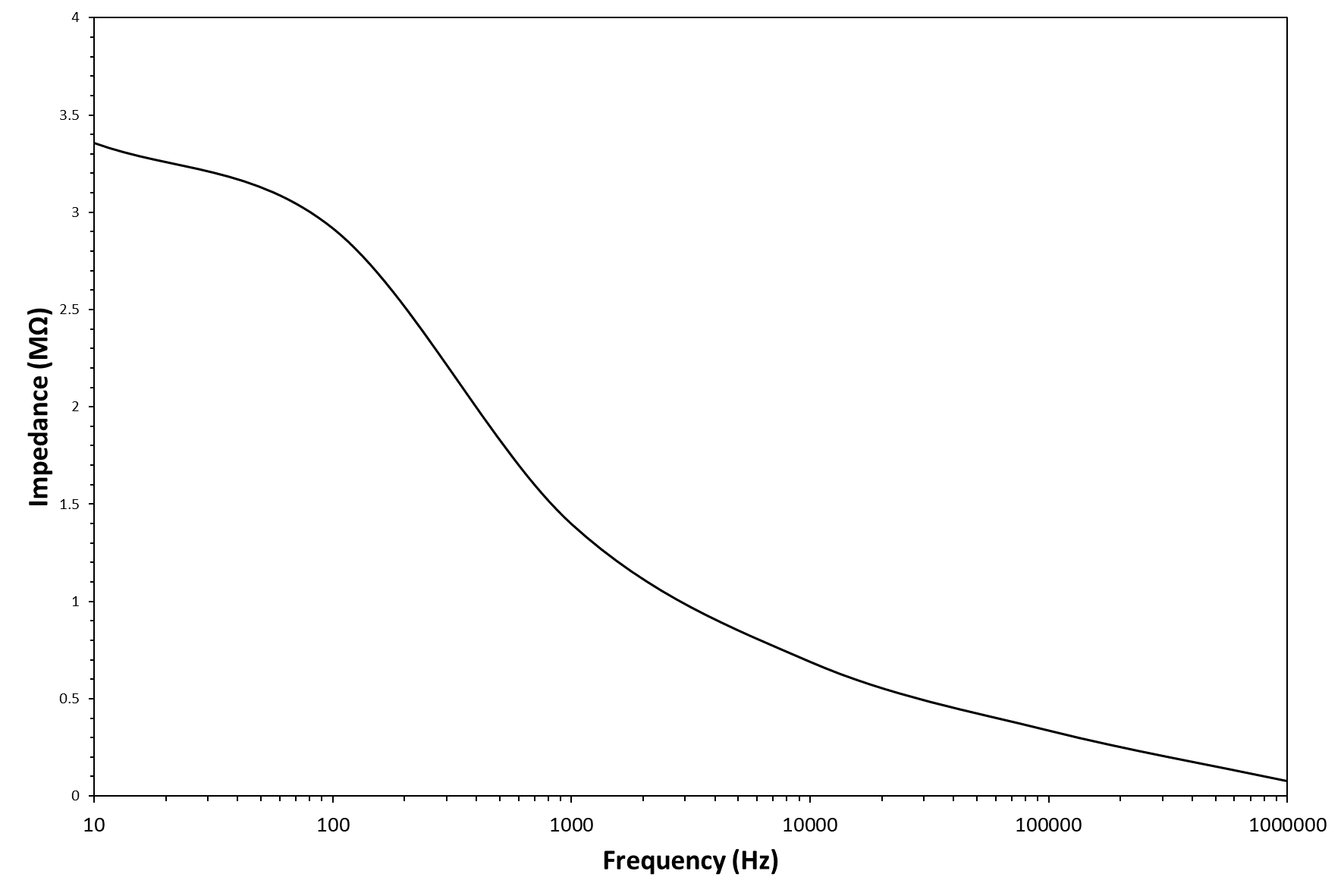
Figure 2 - Electrical scheme of the circuit used for the time-resolved voltamperometric measurements (top image) and clinoptilolite electrical impedance spectrum (bottom image).
2.4 Tortuosity of the cation hopping pathway
The clinoptilolite sample electrically behaves according to the Universal Power Law. This empirical law was first described by Jonscher and refers to a universal dynamic response common to most of ceramic ionic conductors. The law affirms that the sample AC conductivity and angular frequency of the applied electric field are correlated by σ=A·ωn, where ω=2πf, A and n are fitting parameters of an empirical nature and n is generally seen to fall between zero and unity. The n parameter value represents the degree of connectedness of long range charge hopping pathways, or equivalently the extent of tortuosity for mobile charges. The n value can be simply obtained as the slope of a Y vs. frequency graph, because of the analogous expression: Y=Bfn. The clinoptilolite admittance, Y, can be obtained at different frequencies of the sinusoidal signal simply by calculating the I/V ratio (the admittance is the inverse of impedance, Y=1/Z) and this physical quantity behaves for clinoptilolite linearly with frequency in a log-log diagram (see Figure 3). Therefore, also clinoptilolite like several ionic conductors behaves according to the universal power law with a n value of 0.787, which corresponds to a quite low tortuous cation hopping pathway. Therefore, the Jonscher's power low can be used to have an idea of the topological organization of the clinoptilolite porosity. This electrical method based on measuring the sample admittance as a function of the applied voltage frequency allows an estimation for the tortuosity value of the charge carrier (K+ cations) percolative paths and this tortuosity is related to the arrangement of channels in the zeolite crystal. An array of straight channels, as in the case of clinoptilolite, should be characterized by a tortuosity value close to one, while a zig-zag channel organization lowers this value.
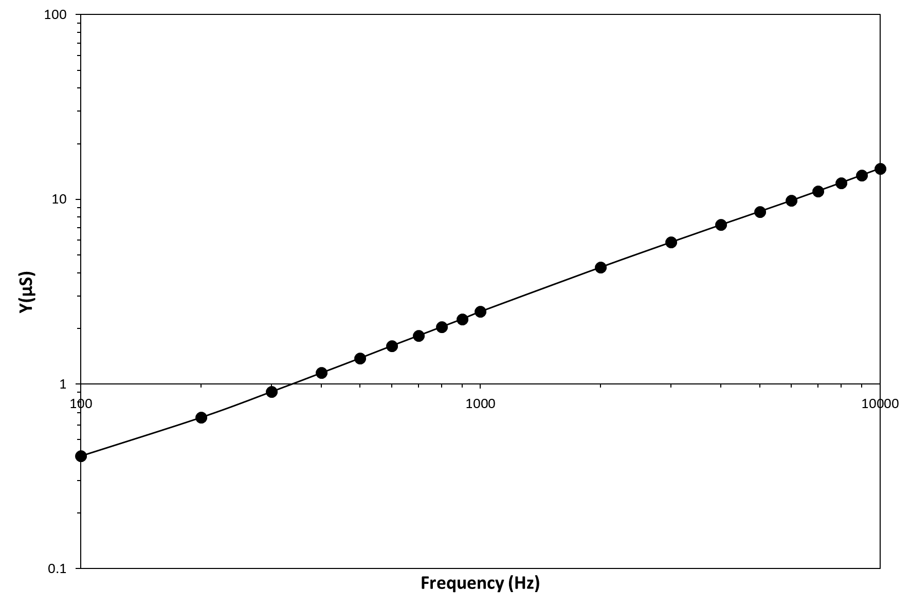
Figure 3 – Graph of the admittance vs. frequency in a log-log scale.
3. NTC-Devices Based on Zeolite
Materials adequate for fabricating NTC devices (e.g., a thermal switch capable of turning on reversibly by heating) must have quite a low electrical conductivity at service temperature (e.g., room temperature) and show significant/rapid change in such a value with increasing in temperature. This device type could be based on zeolites; however, for showing this special electrical behaviour, the Si/Al atomic ratio is a critical parameter and it needs to have a convenient value because zeolite electrical conductivity strictly depends on it. Among the natural zeolite types, clinoptilolite mineral seems to be the best choice for this application because it has an intermediate value of Si/Al atomic ratio, which is capable of guaranteeing electrical insolation at room temperature and a significant electrical conductivity increase with heating (good electrical conductor at high temperature). Indeed, the Si/Al atomic ratio typically ranges from 3.5 to 7 in natural zeolites, and it falls close to 5 for clinoptilolite mineral. In addition, this natural zeolite possesses a number of further useful characteristics that are strictly needed for fabricating inexpensive, stable, and robust devices. For example, clinoptilolite is one of the most common types of natural zeolite, widely available on the market at a very low cost. This material is non-toxic and biocompatible. In addition, differently from other nature-made zeolites, clinoptilolite has good thermal stability (in a wet environment also) and excellent mechanical proprieties for a natural ceramic material, due to the highly compact organization of lamellar crystals in its inner structure. These unique physical/chemical characteristics allow to use clinoptilolite for fabricating robust functional devices that are adequate for an industrial exploitation.
In order to verify the NTC-potentialities of zeolites, a natural clinoptilolite sample has been electrically characterized under the application of thermal pulses. As visible in Figure 3a, the application of a thermal pulse to this monolithic sample promptly generated an electrical micro-current in it. This micro-current grew very quickly with the increase in time after turning on the lamp. During the successive cooling step in air (i.e., turning off the incandescent lamp), the micro-current intensity readily decreased until it reached its starting value, negligibly. The resulting current intensity peak had quite an asymmetric profile because the process of sample cooling in air was slower than the previous heating process. In particular, the heating step followed a linear behavior (see inset in Figure 3b) with a slope of (13.8 ± 0.1) µA/s, while the cooling step followed a hyperbole law. Figure 3b shows the sample behavior under repeated heating/cooling cycles; as visible, four repeated cycles were unable to modify the electric behavior of these NTC materials. The higher value of current intensity that is usually recorded during the first heating step (see Figure 2b) probably represents a hysteresis in the electrical behavior of the dehydrated clinoptilolite sample. Indeed, before electrical characterization, the ceramic samples were only mildly dehydrated by using well-activated silica gel (activation conditions: 5 h at 150 °C under vacuum) and some water molecules (i.e., loosely-bound water) were still present inside the clinoptilolite channels. According to the Vučelić model of the ‘free ionic conduction zone’, these residual water molecules which are adsorbed on the surface of channel walls promote the electrical transport in the material. Differently, water molecules are mostly removed from the sample during the first heating step that takes place at quite high temperatures; therefore, the sample’s electrical conductivity results reduce in all the successive heating cycles of the electrical test, as shown in Figure 3b.
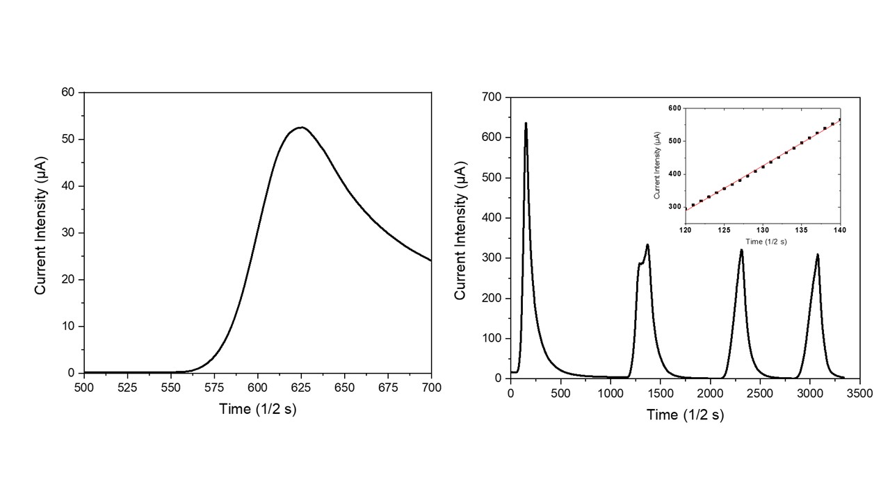
Figure 3. Temporal evolution of effective current intensity in the clinoptilolite sample with the turning on/off of the heat source (a) and NTC material behavior under repeated thermal pulses (b). Linearity of the temporal current intensity behavior is shown in the inset.
4. Conclusions
In conclusion, the clinoptilolite mineral is an electrically conductive material (single charge carrier ionic conductor), and its impedance value has shown a strict dependence on temperature. In particular, surface impedance of clinoptilolite changes readily, substantially, linearly, and reversibly with heating in the temperature range of 25–120°C and above. This electrical performance allows us to suggest the use of NTC devices based on this zeolite type for AC electronic circuits applications as an alternative to traditional semiconductor-based devices.
References
- Moshoeshoe, M.; Nadiye-Tabbiruka, M.S.; Obuseng, V. A review of the chemistry, structure, properties and application of zeolites. American Journal of Materials Science. 2017, 7(5), 196-221.
- Derbe, T.; Temesgen, S.; Bitew, M. A short review on synthesis, characterization, and applications of zeolites. Advances in Materials Science and Engineering. 2021, ID 6637898, 1-17.
- Vucelic, D. Ionic conduction bands at zeolite interfaces. J. Chem. Phys.. 1977, 66, 43-47.
- Vucelic, D; Juranic, N. The effect of sorption on the ionic conductivity of zeolites. J. Inorg. Nucl. Chem.. 1976, 38, 2091-2095.
- Vucelic, D.; Juranic, N.; Macura, S.; SusicM. Electrical conductivity of dehydrated zeolites. J. Inorg. Nucl. Chem.. 1975, 37, 1277-1281.