1. Battery Energy Storage SystemSS Classifications and Characteristics
Energy storage devices with recharging capabilities are used extensively in applications ranging from high-throughput electrical grids to portable low-power devices, because they overcome the problem of renewable energy intermittency and reuse over a long period. Variations in the weather, season, and time of day determine the power output of wind and solar farms
[1][3]. The deployment of rechargeable batteries is extensive, as renewable energy sources are becoming cost-effective for supplying carbon-neutral electric power
[2]. When surplus power is generated, these batteries are charged, and during its absence and connected to load, they are discharged when powered by a charging system
[3][27]. However, for portable applications like
electric vehicles (EVs
), mobile phones, and drones, the device needs to be taken out of operation and connected to the charging system. Batteries gradually degrade over time on repeated charging and discharging. The degradation is accelerated in the presence of temperature fluctuations, excessive variation in charging duration, deep discharges, and cycling partly without fully recharging
[4][1]. A review of the basic chemistry of rechargeable batteries with an overview of characteristics is shown in
Table 1 [5][28]. The characteristics of mature battery technology like lead acid, nickel-based, and lithium-based technology are reviewed in
[6][7][20,29]. The technology and performance of future battery chemistry like sodium batteries, flow batteries, high-temperature batteries, and fuel cell batteries are covered in
[6][8][20,30]. Similar cost, life cycle, energy density, power density, and efficiency of lead-acid, nickel cadmium, and lithium-ion batteries are compared in
[9][31], listing lithium-ion as the best performing at the expense of cost.
Lithium battery research
[22][44] started in 1912, long before lithium-ion batteries became prominent in 1976
[6][20]. By that time, metallic lithium anodes and nonaqueous electrolytes were employed in the initial lithium-metal batteries (LMBs), resulting in substantial enhancements in specific energy and energy density. When Whittingham
[23][45] developed intercalation materials in 1976, research and development of rechargeable LMBs became popular
[24][46]. Rechargeable LMBs have low working potential and high specific capacity, making them candidates for electric vehicle (EV) propulsion despite the fact that safety concerns have impeded commercialization
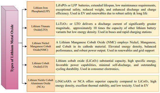
[25][15]. The merits of lithium nickel cobalt aluminium oxide (NCA) in terms of longevity, power density, energy storage, cost, and safety are listed in
[25][15]. A comparison of the major lithium battery chemistries on the basis of cost, life span, performance, safety, power density, and energy density is provided in
[26][16]. The most cost effective lithium battery chemistry is lithium titanate oxide (LTO), while lithium phosphate, lithium manganese, and NMC are equally expensive
[26][16]. NMC and LTO have the maximum life span, whereas LTO has the maximum performance. A summary of the above characteristics for different lithium-based batteries is shown in
Figure 1, with the individual pros and cons of each battery type.
Figure 1. Different types of lithium metal oxides and key characteristics [25][26]. Different types of lithium metal oxides and key characteristics [15,16].
An application-specific battery degradation study considering three applications, i.e., frequency containment reserve, increased self-consumption, and peak power shaving, was carried out in
[27][47]. The study in
[27][47] showed that battery degradation affects most of the peak power shaving applications. The component reliability of BESS was studied in
[27][47] using a life cycle bathtub curve, and it was derived that the highest chance of failure is the DC link capacitor among the the components of the BESS. Lithium-ion battery failure modes were classified and studied in
[28][48]. The failures were classified into anode degradation, cathode failures, separator failures, and current collector failures. The anode failures were further classified into failures of the solid–electrolyte interface, lithium plating, active material, anode structures, and electrolyte decomposition. Cathode failures consisted of failures in cathode structures, active material dissolution, active material isolation, and electrolyte decomposition due to oxidation. Regarding the contribution of the degradation modes to the overall reliability of lithium-ion batteries, loss of active anode and cathode material contributes to nearly 50% of the total capacity and power fades. This contribution increases to 70% after including the loss of lithium inventory. In
[28][48], it is also shown that the solid–electrolyte interface growth with more rate and graphite exfoliation with less rate are significant contributors to the reliability and safety of lithium-ion batteries. A similar classification of lithium-ion degradation was performed in
[29][49], considering the impact of cell level and pack level aspects of batteries on reliability. The chemical and electrical aspects were observed to have the highest impact compared to the mechanical and thermal aspects on battery reliability. The reliability evaluation of thermal management systems and electrical energy storage systems of lithium-ion batteries is proposed in
[30][50]. Redundancy-driven improvement in the reliability of lithium-ion battery packs has been suggested in
[31][32][51,52], which demonstrated that a suitable configuration enhances the battery reliability in EV applications.
The wide range of BESS characteristics cater to the diverse requirements of various applications, depending on the characteristics of the load it is driving. This makes some types of battery suitable for a specific application, while other batteries perform better for other application types. This results in the need to customize the threshold, charging profile, estimation algorithm, computation metric, etc., of the BMS for battery-specific management. Hence, the following section provides a review of BMS functionality and architecture for smart battery management.
2. Battery Management System (BMS)
The battery management system is an electronic device that act as an interface with the battery pack and the load/charger
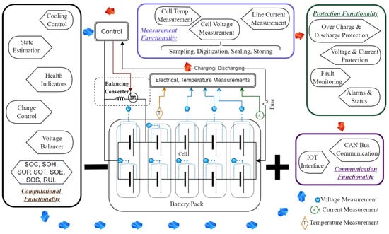
[1][33][3,4]. An efficient BMS is primarily responsible for enhancing battery performance, ensuring safe battery operation, and extending battery life. A BMS is an integrated system that comprises both hardware and software modules, as demonstrated in
Figure 2. A BMS monitors cell voltage, line current, and temperature to estimate battery stress, charge–discharge cycles, and faults. BMS functionalities are broadly segregated into temperature regulation, cell charge balancing, overvoltage, overcurrent and overcharging protection, battery degradation assessment, and usage time prediction
[1][3][3,27]. The hardware components of a BMS include microcontrollers for computation, actuators for control and protection, sensors for data acquisition, and ports for communication. Its main functionalities are as follows
[34][53]:
Figure 2.
Battery management system (BMS).
-
Measurement Functionality: The input cell voltage, battery chassis temperature, and line current signals are acquired by the sensors and digitized with an analog-to-digital converter (ADC). Voltage, current, and temperature values are sampled at a fixed interval, which are then digitized to analog values, scaled to the required level, and stored in memory. Then, time series data are formulated, and metrics and trends are extracted.
-
Protection Functionality: The BMS acts as a first line of defense for a battery against extreme operating scenarios. A battery can be subjected to overcharge with overvoltage and overcurrent, leading to degradation, or it can be overdischarged with high current, resulting in the battery being unusable. Extreme electrical conditions also result in battery temperature rising to dangerous levels, leading to fire hazards. The BMS prevents extreme electrical operating conditions as well as high-temperature variations in the battery. The BMS also monitors for any system faults and dead cells in the battery pack, with the possibility of isolating them if suitable circuit is in place. With the occurrence of faults and damage, the BMS indicates the specific anomaly on the visual alarms and display unit (if present).
-
Computational Functionality: All the computational functions, like charge management, cell voltage balancing, state estimation of the battery, and cooling control, are part of the output functionality of a BMS. Switching the charging mode from constant current to constant voltage is performed by the BMS based on monitoring the voltage and the current measurement functions. Differences in the electrical parameters of individual cells may lead to internal circuit loops, resulting in damage to the cells when operated in series and parallel. The voltage balancing and charge balancing of each cell are important to prevent circulating current loops in the battery. Monitoring HIs and estimating battery states like the SOC, SOH, SOP, SOE, SOF, SOS, etc., are the computations performed by a BMS to maintain high battery performance.
-
Communication Functionality: BMS are typically equipped with communication ports like serial, controller area network (CAN), distributed network protocol (DNP3), and USB ports to connect with the host computer. New BMSs may also have wireless communication capabilities like Bluetooth, WiFi, etc. Communication with BMS smay be required for diagnostics, data downloading, and system updates.
The data acquisition module of a BMS samples the electrical and temperature signal at a rate higher than the Nyquist rate. However, this conventional strategy is inadequate when dealing with signals that fluctuate rapidly, including battery voltage and current. Event-driven ADCs (EDADCs) based on event-driven sensing (EDS) dynamically modify their sampling frequency to reduce the memory requirement and power consumption, enhancing system efficiency and increasing the speed of postprocessing
[3][27]. In
[35][54], the author presents a primary–secondary architecture
[34][53] of battery management that is suitable for EVs. Thermal management, high-voltage protection, and CAN bus communication for data retrieval are some of the BMS functionalities implemented in
[35][54]. A battery management integrated circuit (BMIC) fabricated using 0.18
μ�m high-voltage bipolar Cmos Dmos technology was tested in this
res
earchtudy. The low-power BMIC was effective and compact. The BMIC could monitor a battery pack of 16 cells with sigma–delta ADC and had modules for control, data storage, and fault reporting. In
[7][29], the author provides the comprehensive framework for a BMS consisting of a main fuse as a safety unit, a charging system unit, a balancing control module, a communication module, an internal power supply module, general digital outputs, voltage and current measurement units, a temperature control unit, a global clock module, a general analog, and a digital input. The communication module includes a calibration channel and supports the CAN bus protocol. The general digital output consists of cell balance indicators, SOH indicators, SOC indicators, and fault alarms.
SOC, SOH, SOE, SOP, SOT, SOS, and SOF are the key factors assessed by a BMS. The main focus is monitoring these metrics, leading to improved reliability and ensuring safety
[36][37][55,56]. SOC, SOH, and SOP estimation; cell balancing; overvoltage protection; and thermal protection are the main functionalities of the BMS presented in
[38][57]. An accurate SOC estimation helps a BMS to ensure better battery charging and discharging control. An extensive battery thermal management system is proposed in
[6][39][20,58], with cooling and preheating functionalities for BMS applications. The BMS functions in
[40][59] include protection, high-voltage control, diagnostics for battery state estimation and fault detection, performance management, and interface operation. A review of BMS technology, including battery modeling, battery state estimation, and charging optimization using current, voltage, and temperature sensors, is provided in
[12][34]. A combination of phase-change materials (PCMs) and liquid cooling was used for the purpose of optimized coolant flow and enhanced cooling effect. Three categories of cell balancing methodology were implemented, which were voltage uniformity methods, capacity uniformity method, and an SOC uniformity method. Sensor faults, internal/external short-circuit faults, battery thermal management system faults, overcharge/overdischarge faults, and actuator faults were considered in the BMS’s functionality. AI-powered cyber–physical platforms based on digital twins have also been explored for online large-scale fault detection
[6][41][20,21]. The state estimations such as SOC, SOH, SOT, SOF, and overcharging and discharging protection functionalities of BMSs are reviewed in
[42][60]. Improving rechargeable battery efficiency using a active energy balancing system with integrated SOC and SOH estimation is proposed in
[43][61]. An application of a BMS in a house subscribed to demand-side management (DSM) is proposed in
[1][3]. The data on the battery’s status are transmitted to the load management system to optimize the usage patterns of appliances with variable power requirements, such as washing machines, HVAC, and boilers to improve energy efficiency and save costs
[1][3]. A BMS assists with power supply fluctuations and hthe igh evening demand to optimize device scheduling and battery charging
[3][27].
A hierarchical architecture of a BMS is proposed in
[34][53], in which centralized distributed and modular topologies are considered. The centralized BMS is more cost-effective and the least expandable, while the distributed BMS is the most expensive but easy to assemble. The
res
earchtudy also demonstrated a primary–secondary configuration of a centralized BMS with multiple secondary BMSs connected to a serial interface for electric transportation applications. A comprehensive BMS architecture is presented in
[34][44][53,62], in which charging/discharging control, voltage monitoring, battery balancing, temperature control, and fault diagnosis functionalities are implemented.
In
[45][46][8,63], the concept related to cell balancing is proposed, which is vital to the functionality of BMSs for an extended battery life. Cell balancing is classified into two main categories, passive and active methods. In passive balancing techniques, shunt and bypass resistors are used; on the other hand, active balancing methods use energy transfer of elements like R, L, C, and a semiconductor switch. Between these two methods, active balancing is much better due to its faster cell balancing time, economic use, and higher efficiency. The active balancing circuit uses a charge shuttle and firing capacitors to transfer energy among cells. Inductor-based balancing circuits take less cell balancing time via storing energy in inductors. A detailed cell balancing comparison is provided in
[45][8], covering simple cell balancing methods like shunt resistors to multi-inductor active charge/discharge methods. The shunt-based methods are high in power loss and low in efficiency, at the benefit of being low cost. High-performance methods with switches, inductors, and diodes are significantly more expensive. The BMS presented in
[9][31] has all the major functionalities like charging, cell balancing, state estimation, thermal management, and fault detection. The functionality of traction motor control is also discussed extensively with a cost performance analysis. A performance comparison of EV motor configurations is also described in
[9][31]. In
[47][19], the author presents the future trends in BMSs, which should include increasing accuracy and meeting real-time demands, considering vehicle-to-grid (V2G) technology and emerging technologies such as 5G, increasing BMS bandwidth, and using big data and cloud computing
[48][49][64,65]. A vulnerability study and the means of mitigating cyber-attacks are mentioned in
[50][66]. Defending against false data injection attacks, random delay attacks, confidentiality and availability attacks via model-based, data-driven, and pseudo-measurement generation is the primary focus in
[50][66]. An adversarial reinforcement learning agent is proposed to detect false-reporting attacks of SOC
[50][66]. In
[51][67], the author presented a field-programable gate array (FPGA) implementation of a BMS with a centralized and decentralized architecture. The centralized BMS version is cost-effective but less expandible. In contrast, the decentralized BMS using a primary–secondary architecture is robust and more flexible. The secondary module handles temperature measurement, voltage, and current measurements, and implements cell balancing; the primary module manages communication and battery state estimation. A practical BMS for unmanned aerial vehicles (UAVs) is presented in
[52][68] using the ESP32 microcontroller platform. The proposed BMS uses machine learning and the IoT for real-time data exchange and control through mobile applications. Another FPGA implementation of a BMS is presented in
[51][53][67,69]. State estimation is performed by an FPGA-based BMS design using a Matlab HDL coder. In
[54][70], the author presents the concept of a smart battery consisting of self-reconfigurable multicell batteries (SRMBs) and self-regulated smart cells (SRSCs). The SRMBs use a matrix of switches and sensors for monitoring and controlling the cells in a battery pack, while the SRSC monitors individual cells of the battery, leading to a more expensive solution. A BMS using a digital twin with an extended Kalman filter (EKF) and XGBoost was implemented in
[55][71] for improved state estimation. In
[56][72], a similar digital twin for battery health monitoring is presented with stable hardware, software, and a diagnostic algorithm as advantages. In
[57][73], the author presents a review with the main focus on cloud-based smart BMSs, considering their potential for removing limitations, improving battery algorithms, and enabling advanced BMS functionalities. Blockchain, cloud computing, artificial intelligence, and digital twins have been used to efficiently estimate battery chemical behavior using a BMS in
[57][58][59][73,74,75]. In
[60][76], the author presents a digital twin framework for EV batteries. The physical system has an on-vehicle BMS that gathers real-time data and transmits them to the Azure cloud. The digital model in the cloud estimates the SOH, including incremental fine-tuning of a deep learning network on new data.
In
[61][9], the author presents a review focusing on BMSs, mainly focusing on the remaining useful life (RUL) of batteries, considering the advantages of and challenges ahead for different methods. Estimation of RUL using adaptive filter technologies provided the best estimation measure using an unscented particle filter (UPF), and its variation with estimation error in the range of 0–2% was achieved within 30–32 cycles of charging/discharging. Similar accuracy was also achieved using a combination of empirical mode decomposition, DNN, and LSTM within 30 cycles.
The high penetration of batteries with renewable energy sources poses new challenges and additional requirements for BMSs. A comprehensive list of supplementary tasks of BMS installed for managing batteries in grid energy storage is covered in
[62][77]. The authors in
[62][77] point out that mechanical hazard protection, thermal isolation, and battery pressure release are some of the safety functions of BMSs in batteries used for grid storage systems. Several specialized functionalities of BMSs related to grid management are also listed in
[62][63][77,78], like (a) participation of the grid assets in primary and secondary control, (b) participation in energy arbitrage, (c) optimizing renewable energy supply to daily load demand curves, (d) responding to demand response programs, and (e) improving grid resiliency by minimizing blackouts. The inclusion of life cycle operating and storage cost as optimization objectives in BMSs for renewable energy sources is proposed in
[64][79]. Extending the battery life and improving power quality in the grid are advanced functionalities included in BMS operation in
[64][79]. Large arrays of cells and battery packs are common in grid energy storage systems to obtain rated output voltage and current levels. The reconfiguration functionality of battery packs to achieve balancing, healing, and optimization is proposed in
[65][80]. Grid-scale application requires functionalities like supplying peak power demand, load following, improved stability, power quality, parallel operation, and fulfilling renewable intermittency, which is mentioned in
[66][81]. In
[67][82], BMS functionalities are expanded to cover economic operation, minimizing power loss, and hourly battery scheduling, as well as achieving user-defined objectives. Optimizing the objectives of demand response, minimizing intermittency, and minimizing power loss is demonstrated in
[68][83]. A solar PV was interfaced with a smart grid with a goal of maximizing revenue in a variable tariff market
[69][84].
Recommendations for extending the battery life are listed as controlling four battery features in
[70][85], which are temperature-related features, like (a) minimizing exposure to high temperature during discharge and low temperature during charging; (b) maintaining the SOC at 90% and not at 100% or 0% for a long time; (c) avoiding fast charging and discharging current; (d) prevening moisture exposure, mechanical damage, and follow calibration. Apart from these restrictions, several other goals are considered in
[71][86] for formulating objective functions like (a) cost of operation when connected to a microgrid; (b) cost of storage and expansion considering the time shifting of application to ease grid operation; (c) life cycle cost including installation, operation, and maintenance; (d) degradation cost of battery. A similar cost function minimization is also presented in
[72][87]. Optimal life cycle battery planning is presented in
[73][88] considering (a) fixed revenue obtained from frequency-regulation services, (b) operation and maintenance cost is proportional to the power capacity of a BESS, (c) BESS degradation cost and penalty cost for uncompensated power, (d) BESS second-life operation and maintenance cost, and (e) BESS depreciation cost. An optimized real-time BESS schedule considering total life loss and facilitating economic operation and security of microgrids under stochastic conditions is demonstrated in
[74][89]. The consideration of aging and maximizing lifetime battery profitability is demonstrated in
[75][76][90,91]. A summary of the BMS trends discussed in this
rpape
searchr is presented in
Table 2.
Amongst the many functionalities of BMSs, computing HIs and states of the battery provides important metrics for healthy operation and improving battery longevity. Hence, the selection of the HIs to be computed and the different states to be estimated drives the innovation path of BMSss. In the following section, a review of HIs and battery states and a detailed classification of the methods are provided under suitable groups and subgroups.