Photovoltaic systems are prone to breaking down due to harsh conditions. In photovoltaic systems, various types of faults can cause power loss in some way. To improve the reliability of these systems, diagnostic methods using Machine Learning (ML) have been developed.
- diagnosis
- faults
- photovoltaics
- machine learning
- supervised learning
1. Introduction
2. Photovoltaic Generator Faults
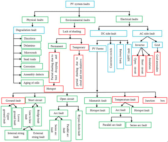
In a photovoltaic system, a fault refers to an atypical behavior that signals a potential loss of power or complete system unavailability. Given the challenging environmental conditions that photovoltaic systems operate in, defects can arise across various components, each with a unique set of issues. These faults may manifest themselves in the photovoltaic array and/or in the inverter, which can partially identify them [28][53]. PV generators can experience different types of faults, which are classified based on the area they affect. These categories comprise electrical, physical, and environmental faults [29][54]. However, faults can occur in photovoltaic systems, with the most common being on the solar panel side. These include shading, mismatch, potential-induced degradation, hotspot, open circuit, short circuit, line-to-line, line-to-ground, arc, bypass, and anti-reverse diode faults. Also, there are different types of faults that can occur in an inverter, which include open-circuit faults, short-circuit faults, insulation faults and so on [30][31][36,55]. The following section provides a detailed explanation of the most common faults provides a detailed explanation of the most common faults found in a photovoltaic installation. This information will help in the diagnostic process. Based on the analysis of Figure 2, the following subsections describe some of the most common faults that can affect a PV installation.2.1. Ground Fault
Ground fault (𝐹1) is an accidental short circuit between one or more current conductors and the earth. It is the most common type of fault that occurs due to cable insulation failure. This fault poses a serious risk as it can produce current arcs at the points of failure, leading to electric shocks. Furthermore, it causes an increase in current in the affected conductors, resulting in imbalances and changes in the architecture of the PV array [32][56].2.2. Short-Circuit Fault (SCF)
A short-circuit fault occurs when two points in a circuit of different potentials accidentally connect [33][57]. This fault can happen within the same module string (intra-string fault 𝐹2) or between two modules of different strings (inter-string fault 𝐹3). Poor wiring between the generator PV and the inverter, animal damage to cables, and water infiltration into the PV modules are the causes of this fault [34][58]. Short-circuited modules result in a drop in network voltage while the current significantly increases. Generally, a short-circuit fault circuit causes a line-to-line fault [35][59].2.3. Line to Line Fault
According to Pillai et al. [30][36], a line-to-line fault happens when there is an unintended short circuit between two points of a PV array with different potentials. This type of fault can occur between modules of the same string or between modules of adjacent strings. It can also occur between conductors of the same circuit with different potentials, without involving any earthing point. Furthermore, when this fault occurs between two modules of the same order from different strings, it is sometimes referred to as a bridging fault [36][60]. The outcome of this fault is a decrease in the open circuit voltage, while the short circuit current may remain unchanged. This voltage reduction results in a modification of the current-voltage characteristics of the photovoltaic field. Please see Figure 3 for a summary of the most common faults in a PV system.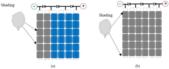
2.4. Open-Circuit Fault (OCF)
An open-circuit fault (𝐹4) occurs when a cable inside a module or a PV module string accidentally disconnects. This fault affects the total resistance of the PV generator and causes a significant increase in the short circuit current [37][61]. However, an open-circuit fault is more damaging than a short-circuit fault due to the increased current flow. The breakage of connection wires between cells or PV modules, faulty diodes, and the deterioration of connection cables usually cause this fault [35][59]. An open-circuit fault is a result of the line-to-line fault, which itself is caused by the short-circuit fault [22].2.5. Arc Fault
An arc fault is a type of fault that occurs when an electrical current passes accidentally through air or another dielectric material [31][55]. Detecting arc faults is a complex process because they occur intermittently. Arc faults can happen within a single conductor (series arc fault 𝐹5) or between two parallel conductors (parallel arc fault 𝐹6). Additionally, faults can occur due to the breakage of insulation cables, which can cause significant noise in the output voltage and current of the PV network [32][56].2.6. Mismatch/Shading Defects
A mismatch fault occurs when a group of photovoltaic cells has different electrical characteristics [38][62]. This type of fault can be permanent, like an open-circuit fault, or temporary, like partial shading. Partial shading is a specific type of mismatch fault and is one of the main causes of failures in a PV system. The shading phenomenon can be classified as uniform or non-uniform [38][62]. The source of uniform shading can be adjacent buildings, passing clouds, trees, other signs, bird droppings, dirt and so on. Non-uniform or partial shading defects occur when some cells or modules receive direct irradiation and temperature in a non-uniform manner. On the other hand, uniform or total shading occurs when all cells or modules receive uniform but reduced exposure, resulting in a constant reduction in the output current and voltage of individual cells in a string. It is important to note that technical abbreviations should be explained the first time they appear [39][63]. Figure 3 shows a partially shaded and fully shaded module. The setting of the sun causes shading of the photovoltaic (PV) module, which reduces its power output. It is important to note that although shading has a negligible impact on the PV module’s overall performance, it should still be avoided. Shaded cells can become reverse polarized, consuming energy instead of producing it, leading to a drop in power and the hotspot phenomenon [40][64]. The hotspot phenomenon can accelerate the aging process of the PV system and may even lead to an open-circuit fault or fire risks [41][65]. Figure 4 provides an illustration of the various faults described above.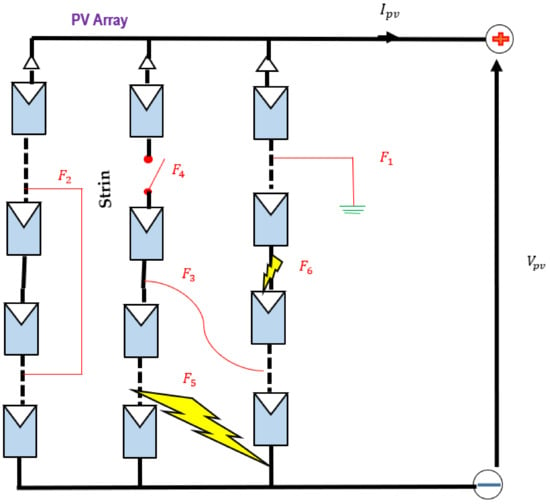

3. PV Inverter Faults (PVI)
In photovoltaic applications, one of the biggest challenges is ensuring that power electronics are reliable in order to optimize energy production. The inverter serves as the interface between the photovoltaic generator and the network and/or load. Its main function is to convert the continuous energy produced by the photovoltaic modules into alternating energy that is identical to the network. This allows the inverter to access electrical information from the generator and the electrical network, making it an intermediary between the two. Additionally, the inverter is equipped with a high level of data granularity, which enables it to detect electrical anomalies in real-time and alert the user through an audible signal or a message. However, despite its advantages, the inverter is vulnerable and subject to faults. During its operation, it is exposed to overvoltage and overcurrent constraints due to transient operating conditions, mechanical turbulence, temperatures, and humidity [44][68]. The IGBT (insulated gate bipolar transistor) power switch, being the main energy transfer component, is the most likely source of failure in the photovoltaic inverter [45][69]. The most common faults that can occur during the inverter’s operation are open-circuit, insulation faults and short-circuit faults [46][70].3.1. Short-Circuit Fault
A fault can occur due to breakage of the connection wire, deterioration of the gate circuit, or overcurrent. However, a short circuit happens very quickly, making it difficult to detect. Shortly after appearing, it transforms into an immediate open-circuit fault [47][71]. Short-circuit faults automatically shut down the system, making them more dangerous than open-circuit faults.3.2. Open-Circuit Fault
An open-circuit fault can occur in a photovoltaic system due to a disconnection of the jumper wire, overheating, or a device driver fault, resulting in a broken connection. Unlike a short-circuit fault, an open-circuit fault may not immediately affect the inverter, but if left unaddressed, it can lead to serious accidents with other components [47][71]. This is because an open-circuit fault distorts the output current of the inverter, causing an increase in the total harmonic ratio, which does not meet the grid connection requirements. Table 1 provides a list of main faults that can occur in a photovoltaic system, and Figure 6 illustrates an overview of the open-circuit fault that can occur in the IGBT transistor of a PV inverter.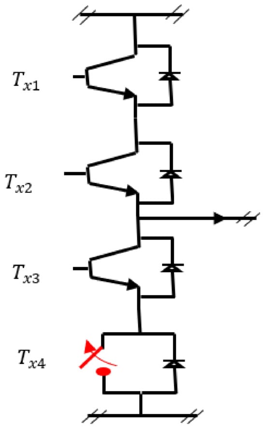
|
Type of Defects |
Causes |
Effects |
Consequences |
||
|---|---|---|---|---|---|
|
Internal |
Short circuit |
Manufacturing defect |
Low impedance, blocked path between internal power rails |
Reduction of power produced |
|
|
Cell microcracks |
Manufacturing defect |
Difference in module characteristics |
Unable to deliver power to the load |
||
|
Broken modules |
Shock during transport |
||||
|
Degraded modules |
Aging |
Drop in power delivered |
Low production |
||
|
Bypass diode |
Manufacturing defect, wiring defect |
Can’t drive |
Unable to prevent the appearance of hot spots, electric arc, fire risk |
||
|
Open circuit |
Manufacturing defect, wiring defect |
Lack of access path for the power produced |
No power produced |
||
|
External |
Mismatch fault |
Temporary |
Temporary shading |
Cloud |
Drop in production, risk of fires |
|
Permanent |
Equipment damage |
Blackout |
No production |
||
|
Shading |
Temporary |
Passage of clouds, weather conditions |
Uneven distribution of irradiation on the surface of the modules |
Drop in power produced |
|
|
Natural disaster |
Module reverse bias |
Hot spot/fire hazard |
|||
|
Permanent |
Partial shading |
||||
|
PV field |
Short circuit |
Bad wiring between inverter and PV field, chewing of cables by animals, water infiltration into modules |
Drop in network voltage and increase in current |
Drop in production |
|
|
Open circuit |
Accidental breakage of connecting cables |
Drastic drop in short-circuit current |
Drop in production |
||
|
Line to line |
Faulty connection link between the different rail circuits |
Power loss |
Reduction of open circuit voltage, modification of characteristic IV of the PV field |
||
|
Arc fault |
Accidental passage of current in a dielectric |
Strong noise in currents and voltages |
Fire hazard |
||
|
Line to ground |
Ground wiring fault, corrosion |
Drop in network voltage and increase in current |
Risk of electrocution, variable voltage |
||
|
PV inverter |
Inverter open circuit |
Absence of gate control, connection wire breakage due to high short-circuit current, external disconnection due to vibrations |
Deterioration of phase current and torque |
External radiation |
|
|
Inverter short circuit |
High gate voltage, delamination and cracking in the solder layer, static locking and high temperature |
Excessive leakage current, affected phase current close to zero |
Temperature variation |
||
|
Insulation fault |
Humidity, high heat, poor connection in the solar panel junction box, aging of solar panels |
No power |
|||
|
Grid |
Grid anomalies |
Electrical overload, deterioration of conductive insulators |
Network disruption, voltage dips and peaks, harmonics |
Interruption of current flow, short circuit |
|
