Your browser does not fully support modern features. Please upgrade for a smoother experience.
Please note this is a comparison between Version 1 by Jialiang Wang and Version 2 by Catherine Yang.
Ultra-high-performance concrete (UHPC) is an advanced cement-based material with excellent mechanical properties and durability. However, with the improvement of UHPC’s compressive properties, its insufficient tensile properties have gradually attracted attention.
- UHPC
- tensile strength
- steel fiber
- fiber content
1. Introduction
Ultra-high-performance concrete (UHPC) is one of the latest advances in concrete technology and is a new concrete series [1]. Compared to conventional concrete (CC), UHPC shows superior mechanical properties, durability, and ductility after cracking [2][3][4][5][2,3,4,5]. At present, there is no widely accepted definition of UHPC, but it is generally considered that its compressive strength is ≥150 MPa and its tensile strength after cracking is ≥5 MPa [6][7][6,7]. Under the same bearing capacity, the weight of a structure made of UHPC is only 1/3~1/2 that of CC [8]. Therefore, UHPC is often used in long-span structures and high-rise buildings. In addition, UHPC is, furthermore, energy efficient and environmentally friendly when considering the entire life cycle of the building [6].
The tensile strength is an important factor that affects the overall performance of concrete structures, and it is, therefore, crucial to have the correct material input in the design calculations [9]. In some projects, structural damage is often caused by an insufficient tensile strength and compression zones that have not reached their bearing limits. Steel fibers are crucial for improving the tensile properties of UHPC, so it is important to investigate the effect of steel fibers on the tensile strength of UHPC. Usually, the common methods to improve the tensile properties of UHPC by steel fiber are as follows [10][11][12][13][10,11,12,13]: (a) increase the fiber content; (b) use different types of fibers; (c) increase the fiber length; (d) hybrid of different types of fibers. However, due to the complexity of the fiber geometry and the uncertainty of the fiber distribution direction, the tensile properties of UHPC materials vary greatly [14][15][16][17][18][14,15,16,17,18]. At the same time, the physical properties of the steel fibers and the bonding strength between the fibers and the UHPC matrix also affect the mechanical properties of the UHPC [17][19][20][17,19,20]. This is also a core factor to be considered in structural design. In addition, the steel fibers are also the main reason for the high cost and carbon footprint of UHPC [21]. Therefore, combing and summarizing the knowledge of steel fibers on the tensile properties of UHPC is beneficial for improving the structural design theory of UHPC and reducing the carbon footprint.
With the application of UHPC to engineering practice, the issue of insufficient tensile properties has received increasing attention [22]. By reviewing the latest reviews of UHPC, it was found that the reviews of the effect of steel fiber on the tensile strength of UHPC lacks its influence on the splitting tensile strength [20][21][23][24][25][26][27][28][20,21,23,24,25,26,27,28], which must be supplemented. It is very important to detect the cracks in concrete, which is usually carried out by optical means or an extensometer [29]. Digital image correlation (DIC) technology is a non-contact, modern optical measurement experimental technology, which can directly measure the mechanical behavior of materials and structural surfaces. Due to its high measurement accuracy and operation, it has gradually attracted more and more attention in the research on UHPC, especially for the tensile behavior of steel fibers-reinforced UHPC.
2. Advantages and Significance of Steel Fibers in Concrete
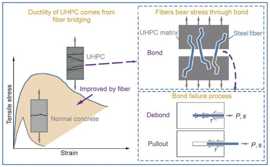
Concrete is a quasi-brittle material according to its macroscopic mechanical behavior. As its strength increases, its brittleness increases correspondingly, with the disadvantages of low tensile strength and minor ultimate elongation. To overcome these shortcomings, many researchers have incorporated steel fibers into concrete and have proven its feasibility [30][31][32][30,31,32]. Steel fibers can improve the ductility of the cement matrix by bridging cracks, thus, improving the brittle fracture of concrete [33][34][35][33,34,35]. Usually, adding steel fibers into concrete can play two main roles: (a) improving the tensile strength and (b) preventing the occurrence and propagation of cracks. Figure 1 shows that compared with normal concrete, the tensile strength and toughness of UHPC when steel fibers are added are significantly improved. Steel fiber is one of the most commonly used fibers in UHPC. Those properties related to the tensile strength of a UHPC depend largely on the content and geometric size of the steel fiber [21][37][21,37]. The geometric differences among (in Figure 2) and fiber content (vol.%) of steel fibers have been discussed in many studies [38][39][38,39]. The motivation for this kind of research is that steel fiber makes an important contribution to the tensile properties, and steel fiber is one of the most expensive materials in UHPC [21]. Therefore, discussing the influence of steel fiber on UHPC is beneficial for improving the tensile strength of UHPC, reducing the cost of UHPC, and making it more suitable for engineering practice.
Figure 2.
Common types of steel fibers. (
a
) Straight; (
b
) corrugated; (
c
) hooked-end; (
d
) twisted.
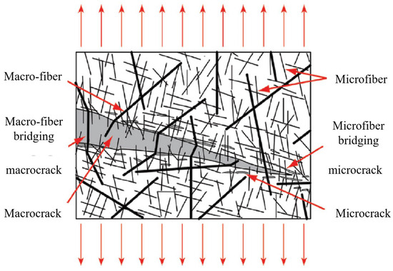
Figure 3.
3. DIC Application to Tensile Properties of UHPC
3.1. The Basic Principle of DIC
As mentioned before, direct tensile tests are difficult to use to detect the expansion of main cracks using traditional methods. Bending tensile tests often use notched specimens to predetermine the location of crack initiation, and are not suitable for detecting multiple cracks. DIC is a nondestructive and non-contact optical, full-field deformation test [40][41][42][43][44][45][46][42,70,77,79,81,86,91]. By spraying black and white spots on the surface of the UHPC specimen, a high-definition camera and Vic-Snap software are used to collect the image data. The region to be analyzed is then selected using Vic-2D software [40][42]. The displacement and deformation are reflected by comparing the unchanged points (𝑥, 𝑦) of the image subset to (𝑥1, 𝑦1) in the deformed state (in Figure 14). The horizontal 𝑈(𝑥,𝑦) and vertical 𝑉(𝑥,𝑦) displacement fields are calculated by Equations (134) and (235) [40][46][42,91]. The Lagrangian strain field is derived from the displacement field, so as to determine the local cracking zone of the UHPC. Because of the anisotropy of the materials and the geometric shape that affects the shrinkage distribution, DIC can measure the non-uniform surface displacement, which cannot be detected by traditional LVDT [43][79]. Figure 15 is a schematic diagram of the inability of LVDT to capture the horizontal and vertical deformations at the same time [47][84]. Therefore, it is significant that DIC technology can be used to study the tensile post-crack curve of UHPC.


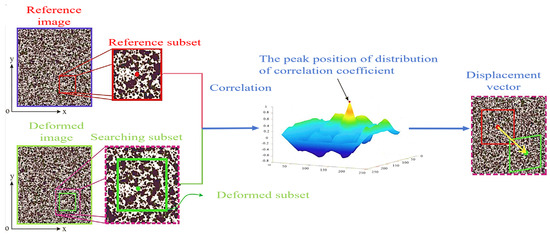


The principle of DIC [128].
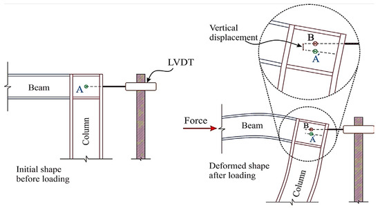

Figure 15. LVDT cannot capture deformation under horizontal and vertical displacement simultaneously [48].
LVDT cannot capture deformation under horizontal and vertical displacement simultaneously [128].
3.2. The Role of DIC in the Tensile Properties of UHPC
According to previous studies, the tensile properties of UHPC are closely related to the crack propagation process, especially in the post-crack phase [49][50][51][60,65,129]. Figure 16 depicts the different regions of crack growth behavior in UHPC. The cracking of UHPC beams under a flexural load is divided into three regions: the uncracked zone, fracture process zone, and macro-crack zone [45][86]. Some researchers believe that there is a micro-fracture zone in the fracture process zone and macro-crack zone, which are called the location zone [41][43][70,79]. The crack widths in the fracture process zone and the beginnings of the macro-crack zone are 0.022 mm and 0.05 mm, respectively [41][43][45][70,79,86]. As can be seen from Table 19, DIC is mainly used to characterize the crack propagation mechanism with respect to the tensile properties. Quantifying the strain field and displacement field around the crack, the crack opening displacement of the UHPC, and the deflection of the beam at the crack help to verify the measurement results of the LVDT. Arora et al. [40][42] presented the effect of the UHPC composition on crack propagation through the combination of mechanical testing and DIC, to better understand the relationship between the material design and performance characteristics of interest. Karim et al. [41][70] used DIC to obtain first-hand information about the width and depth of the cracks observed in the flexural members, thus, evaluating the influence of steel fibers on crack propagation. Niu et al. [42][77] used DIC to determine the strain of the first-cracking and the rate of crack propagation. Some researchers have used DIC to analyze the crack shape and length under flexural tensile strength. These show that DIC is widely used to analyze the time evolution of fracture opening displacement, fracture length, and the local strain field [44][45][52][81,86,130]. At the same time, DIC effectively avoids the complex problem of traditional strain gauge arrangement and is conducive to studying the contribution of different steel fibers to crack growth.
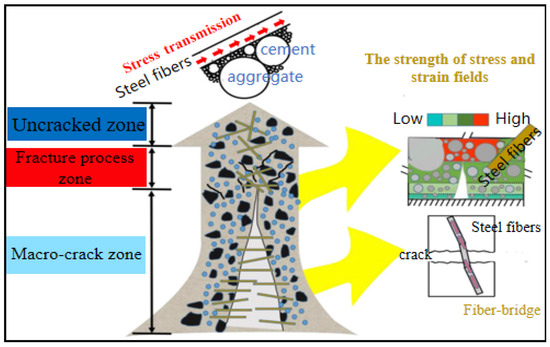

Crack propagation behavior in different regions of UHPC [86].
Table 19.
Application of DIC to steel fiber-reinforced UHPC.
| Ref. | Fiber Combination | Fiber Shape | Application of DIC to UHPC |
|---|---|---|---|
| [40][42] | Single | Straight | (a) Characterize the main cracks and secondary cracks of the UHPC. (b) Analysis of the strain field at different load values. |
| [41][70] | Single + Hybrid | Hooked end | (a) Analysis of the strain field representing different deflections. (b) The maximum crack width of the UHPC reinforced with different steel fibers shapes. (c) Quantify the crack width within the depth range of the sample. |
| Twisted | |||
| Straight | |||
| [42][77] | Single + Hybrid | Straight | (a) Characterize the crack shape and strain distribution under different load values. (b) Quantify the crack width within the depth range of the sample. (c) Quantification of the crack growth rate. |
| [43][79] | Single | Straight | (a) Comparison of the strain cloud maps and failure patterns for the different specimens. |
| Hooked end | |||
| [44][81] | Single + Hybrid | Straight | (a) Characterize the crack shape and strain distribution under different load values. (b) Quantify the crack width within the depth range of the sample. |
| [45][86] | Single | Straight | (a) Characterization of horizontal displacement field of UHPC in different loading stages. (b) Changes in crack propagation in different loading stages. (c) Displacement of crack opening in different loading stages. |
| [46][91] | Single | Straight | (a) Comparison between DIC and traditional LVDT measurement methods. (b) Quantify crack width over a range of specimen heights. (c) Characterize the strain distribution under different load values. |
| [53][131] | Single | Straight | (a) Crack propagation in different loading stages. (b) Crack width in the range of sample depth under different loads. |

