Your browser does not fully support modern features. Please upgrade for a smoother experience.
Please note this is a comparison between Version 2 by Camila Xu and Version 1 by Mattia Maltauro.
A product’s geometrical specification is the result of so-called tolerancing activity. A product specification represents the information contained in the technical product documentation (TPD) stating the product requirements.
- tolerance specification
- functional specification
- functional tolerancing
1. Introduction
A product’s geometrical specification [1,2][1][2] is the result of so-called tolerancing activity [3]. A product specification represents the information contained in the technical product documentation (TPD) stating the product requirements [4]. The geometrical specification is created during the product development phase, and it allows to transpose definite functional requirements into geometrical requirements assigned to actual product features [5,6,7][5][6][7]. The information incorporated in the geometrical specification is shared between departments involved in product development via technical engineering documentation (2D drawings). Alternatively, model-based definition (MBD) is a tool that allows one to represent technical product documentation contents, including geometrical specification, directly into a 3D annotated CAD model [8,9][8][9]. Both are possible forms for TPD [10].
In the ISO standard system on geometrical product specifications (ISO-GPS, managed by ISO/TC213), the concepts recalled above are presented in ISO/TS 21619:2018, which lists the basic types of documents relating to geometrical product specifications: functional specification, manufacturing specification, and verification specification [11]. This document, a technical specification, inherits an ambiguous use for “specification” already existing in ISO publications: it is defined both as a “document stating requirement” [11], using the definition from ISO 9000:2015 [4], and as “expressing the field of permissible deviation of a characteristic of a workpiece as permissible limits” in ISO 17450-1:2011 [12]. Within ISO-TPD (technical product documentation, as managed by ISO/TC10), different types of specifications (e.g., general specification, performance specification, process specification, requirement specification, etc.) are considered as documents [10].
2. Responsibilities in Tolerancing Management
In the current product development cycle, three different key actors can be identified: design, manufacturing, and quality control departments.2.1. Design Department
In the context of this work, the design department (Figure 1) has the responsibility to develop a geometric model for parts and assemblies that fulfils the functional requirements stated in the product requirements document (PRD) [54][13].
Figure 1. Input/output diagram that describes the functional tolerancing activity that takes place inside the design department. Other tasks performed by the design department are omitted.
2.2. Manufacturing Department
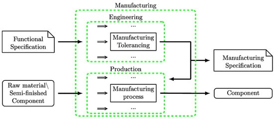
The manufacturing department (Figure 2) is responsible for producing parts and assemblies as defined in the TPD.
Figure 2. Input/output diagram that describes the manufacturing tolerancing activity taking place inside the manufacturing department. Other tasks performed by the manufacturing department are omitted.
2.3. Quality Control Department
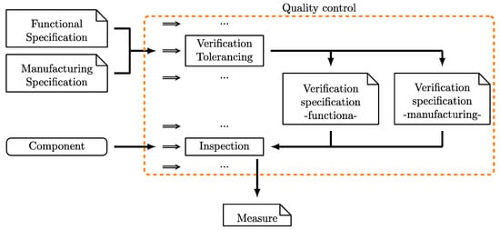
The quality control department (Figure 3) is mainly responsible for the acceptance or rejection of the production batches and may also support the manufacturing department in statistical process control.
Figure 3. Input/output diagram that describes the verification tolerancing activity taking place inside the quality control department. Other tasks performed by the quality control department are omitted.
2.3.1. Functional Inspection
Functional inspection is based solely on functional specifications and is the only inspection that should be used to verify conformity, particularly in a supplier–customer relationship. Emphasis should be devoted to ISO 14253-1:2017 to define conformity [56][16]. The focus of the metrological check is ensuring the parts can perform the intended function and ensuring their interchangeability. Geometric functional inspection may be used to qualify a new supplier, to approve an incoming batch of parts, for selective assembly, etc. The definition of critical-to-quality (CTQ) tolerances and/or the use of functional gauges to speed up inspection may be beneficial, particularly for inbound batch approval [51][15]. The study of the correlation among different characteristics can be used to define CTQ tolerances and to estimate the value of unmeasured quantities [57][17]. Selective assembly allows the creation of functional assemblies when the manufacturing process is not capable of guaranteeing interchangeability [58][18]. Parts can be clustered into different groups, and, once paired together, these groups guarantee assemblability.2.3.2. Manufacturing Inspection
Inspection based on manufacturing specifications plays a significant but different role. In this case, the scope goes beyond checking for conformity to the specification. Here, the emphasis is on process monitoring, e.g., statistical process control (SPC), process tuning, in-line checks, etc. When performing SPC, the aim is to check whether the manufacturing process remains stable. At the beginning of the manufacturing process, fine-tuning of the process allows one to determine appropriate process parameters. Geometric inspections are crucial to assess actual deviations of the manufacturing process in order to perform corrective actions. The directionality of deviations is crucial to determine possible corrective actions; however, directional information is lost when reporting geometrical error according to the ISO GPS standard [12,59][12][19]. In a verification specification dedicated to process tuning and/or SPC, directional information should be defined [51][15]. At the same time, conformity of intermediate stages of the workpiece to the corresponding manufacturing specification might be considered. The economic benefit of such metrological checks can be evaluated according to the procedure presented by Savio et al. [60][20].References
- ISO 14638:2015; Geometrical Product Specifications (GPS)—Matrix Model 2015. ISO International Organization for Standardization: Geneva, Switzerland, 2015.
- ISO/TR 14638:1995; Geometrical Product Specification (GPS)—Masterplan 1995. ISO International Organization for Standardization: Geneva, Switzerland, 1995.
- Morse, E.; Dantan, J.Y.; Anwer, N.; Söderberg, R.; Moroni, G.; Qureshi, A.; Jiang, X.; Mathieu, L. Tolerancing: Managing Uncertainty from Conceptual Design to Final Product. CIRP Ann. 2018, 67, 695–717.
- ISO 9000:2015; Quality Management Systems—Fundamentals and Vocabulary 2015. ISO International Organization for Standardization: Geneva, Switzerland, 2015.
- ASME. ASME Y14.5—2018—Dimensioning and Tolerancing 2019; ASME: New York City, NY, USA, 2019; p. 344.
- ISO 17450-2:2012; Geometrical Product Specifications (GPS)—General Concepts—Basic Tenets, Specifications, Operators, Uncertainties and Ambiguities 2012. ISO International Organization for Standardization: Geneva, Switzerland, 2012.
- Pierre, L.; Anselmetti, B.; Anwer, N. On the Usage of Least Material Requirement for Functional Tolerancing. In Proceedings of the Procedia CIRP, Nantes, France, 23–25 May 2018; Volume 75, pp. 179–184.
- Pinquié, R.; Rivest, L.; Segonds, F.; Véron, P. An Illustrated Glossary of Ambiguous PLM Terms Used in Discrete Manufacturing. Int. J. Prod. Lifecycle Manag. 2015, 8, 142–171.
- ISO 16792:2021; Technical Product Documentation—Digital Product Definition Data Practices 2021. ISO International Organization for Standardization: Geneva, Switzerland, 2021.
- ISO 10209:2012; Technical Product Documentation—Vocabulary—Terms Relating to Technical Drawings, Product Definition and Related Documentation 2012. ISO International Organization for Standardization: Geneva, Switzerland, 2012.
- ISO/TS 21619:2018; Geometrical Product Specifications (GPS)—Types of Documents with GPS 2018. ISO International Organization for Standardization: Geneva, Switzerland, 2018.
- ISO 17450-1:2011; Geometrical Product Specifications (GPS)—General Concepts—Model for Geometrical Specification and Verification 2011. ISO International Organization for Standardization: Geneva, Switzerland, 2011.
- Ishrat, N.Z. Product Management: The Art and Science of Managing Network and Communications Industry Products; Xlibris Corporation: Bloomington, IN, USA, 2013.
- ISO/TS 8062-2:2013; Geometrical Product Specifications (GPS)—Dimensional and Geometrical Tolerances for Moulded Parts—Rules 2013. ISO International Organization for Standardization: Geneva, Switzerland, 2013.
- Maltauro, M.; Morse, E. Towards a Definition of “Geometric Verification Specifications” within the ISO GPS System. Procedia CIRP 2023, 119, 339–344.
- ISO 14253-1:2017; Geometrical Product Specifications (GPS). Inspection by Measurement of Workpieces and Measuring Equipment. Decision Rules for Verifying Conformity or Nonconformity with Specifications 2017. ISO International Organization for Standardization: Geneva, Switzerland, 2017.
- Popa, M.S.; Kortekamp, M.; Aclan, M. Correlation of Geometrical Specifications for Flexible Quality Control in the Manufacturing of Plastic Products. Teh. Vjesn.—Tech. Gaz. 2021, 28, 1456–1461.
- Lanza, G.; Haefner, B.; Kraemer, A. Optimization of Selective Assembly and Adaptive Manufacturing by Means of Cyber-Physical System Based Matching. CIRP Ann. 2015, 64, 399–402.
- ISO 1101:2017; Geometrical Product Specifications (GPS). Geometrical Tolerancing. Tolerances of Form, Orientation, Location and Run-Out 2017. ISO International Organization for Standardization: Geneva, Switzerland, 2017.
- Savio, E.; De Chiffre, L.; Carmignato, S.; Meinertz, J. Economic Benefits of Metrology in Manufacturing. CIRP Ann. 2016, 65, 495–498.
More
