Your browser does not fully support modern features. Please upgrade for a smoother experience.
Please note this is a comparison between Version 1 by Willi Zschiebsch and Version 3 by Mona Zou.
Structural supercapacitors (SSCs) are multifunctional energy storage composites (MESCs) that combine the mechanical properties of fiber-reinforced polymers and the electrochemical performance of supercapacitors to reduce the overall mass in lightweight applications with electrical energy consumption. These novel MESCs have huge potentials, and their properties have improved dramatically since their introduction in the early 2000’s. However, the current properties of SSCs are not sufficient for complete energy supply of electrically driven devices. To overcome this drawback, the aim of the current study is to identify key areas for enhancement of the multifunctional performance of SSCs. Critical modification paths for the SSC constituents are systematically analyzed. Special focus is given to the improvement of carbon fiber-based electrodes, the selection of structural electrolytes and the implementation of separators for the development of more efficient SSCs. Finally, current SSCs are compared in terms of their multifunctionality including material combinations and modifications.
- structural supercapacitors
- multifunctional energy storage composite (MESC)
- carbon fiber electrode
- structural electrolyte
- separator
1. Introduction
The ongoing global warming, the scarcity of resources, and the environmental crisis are changing the way humanity thinks about energy, in particular energy for transportation. Considering the electrification of transportation vehicles as one promising approach for the decarbonization of the transport sector, the demand for more efficient energy storage rises [1]. With motors achieving close to maximum efficiency and electrical storage systems nearing the thermodynamic limit of energy density [2], a major factor that can still be improved is the weight of vehicles, where a reduction results in a lower overall energy consumption [3].
There are two main approaches for structural electrical energy storage (EES) systems. A classical approach is to increase the specific energy density of the active material in order to store the same amount of energy within a smaller portion of EES [4]. A novel approach is to integrate EES into lightweight structures such as structural components made of carbon fiber-reinforced polymers (CFRPs), which can be used for energy storage and load bearing at the same time. The results of this approach are called multifunctional energy storage composites (MESCs). The MESC concept results in the reduction in the monofunctional weight-bearing elements of the EES and therefore increases the overall specific energy density [5].
2. Electrode Material
The electrodes and its interface are responsible for the amount of charge stored inside the SC. Depending on the type of SC, the electrode can either electrostatically store charges for electric double-layer capacitors (EDLCs), undergo charge transfer reactions in pseudocapacitors, or perform both functions in hybrid capacitors. Porous carbon-based materials are commonly employed as electrode materials in EDLCs [6][26]. The capacitance of EDLC devices primarily originates from the accumulated charges at the interface between the electrode pores and the electrolyte [7][8][27,28]. Therefore, parameters such as high SSA, high electrical conductivity, high redox activity, and cycling behavior are crucial properties for SC performance. Typical electrode materials with pseudocapacitive behavior are often associated with transition metal oxides (MOx), such as RuO2 [9][10][29,30] and MnO2 [11][12][31,32], in aqueous electrolytes [6][26]. Although transition metal oxides frequently do not possess the mechanical properties suitable for direct usage in SSCs, they are commonly combined with carbon-based materials, such as carbon nanotube nickel (CNT-Ni) foams [13][14][33,34], to enhance their performance.
Promising material candidates for usage as electrode materials in SSCs include CFs (Figure 13b), CNT fibers (Figure 13c), and graphene fibers (Figure 13d). These materials exhibit extraordinarily high strength, high Young’s modulus values, high SSA, and high electrical conductivity. However, large-scale fabrication methods to produce CNT or graphene fibers are currently challenging and need to be further developed.
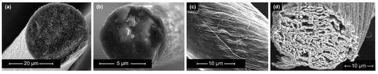
Figure 13. Scanning electron microscopy images of the microstructure of selected carbon-based electrode materials: (a) porous carbon fiber manufactured by the “Research Center Carbon Fibers Saxony” (RCCF) of TU Dresden, (b) single fiber of carbon roving (Tenax HTA 5131 800tex, Teijin Carbon Europe, Wuppertal, Germany) (c) carbon nanotube fibers (reproduced from [15][35]), (d) graphene fiber (reproduced from [16][36]).
In comparison with conventional CFs, the Young’s modulus of graphene fibers is lower [17][18][37,38]. Nevertheless, the first implementation of graphene fibers into an all-solid-state SSC was performed by Senokos et al., which resulted in high multifunctionality [19][8]. In general, the application of CNT fibers and graphene fibers as electrode material in SSCs can potentially obtain comparably high mechanical and electrochemical performances [20][21][22][39,40,41]. Additionally, a promising feature is that guest materials can directly be embedded into these fibers, which leads to an increase in the electrochemical performance [23][42].
As mentioned above, carbon-based materials are widely utilized as the primary material for the electrodes in SCs owing to their favorable polarizability and ability to withstand high temperatures. It appears that the most practical choice for SSC electrodes are carbon-based fibers. There are various SSC electrode fabrication techniques, which involve the utilization of nonwoven CF mats [24][43], UD CFs [25][44], or woven CF mats [26][45] (Table 1). Although nonwoven CF mats exhibit lower mechanical strength compared to the other two, they can still be considered to be suitable for implementation in SSCs due to their higher SSA. This leads to enhanced power and energy densities. Woven CF fabrics and UD CFs, on the other hand, can withstand much higher forces, whereby UD fibers can bear high loads in one certain direction. Additionally, they both can conduct electricity, and thus they can act as current collectors [23][42].
Table 1. Comparison between different carbon fiber fabrics and their properties.
 |
 |
 |
|
|---|---|---|---|
| CF | Unidirectional | Woven | Non-Woven |
| Load bearing capability * | ++ | ++ | + |
| Specific surface area * | + | + | ++ |
| Electric conductivity * | + | + | 0 |
* Assessment of properties: 0 — none, + — good, ++ — high.
Conventional CFs (Figure 13b) are characterized by a relatively dense structure of multiple graphite layers, which results in high mechanical properties and relatively good electrical conductivity. However, they provide low electrochemical properties in comparison to other carbon-based fibers [27][46]. As an alternative solution, porous CFs (Figure 13a) have been recently introduced as a candidate electrode material in SSCs. Porous CFs have a higher SSA due to an intentional increase in the material’s porosity. As a result of this increase, the specific capacitance rises at the expense of a decline in mechanical properties. Consequently, the ongoing research focuses on improving the SSA and electrical conductivity of CF-based electrodes while retaining high mechanical properties. According to Frackowiak and Béguin [28][47], there are different methods, such as activation, heteroatom doping, and surface deposition, for enhancing the SSA of carbon materials, which are summarized in Figure 24. These modifications are explained in more detail in the following sections.
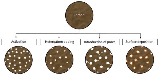
Figure 24. Schematic illustration of the modifications of carbon material for the usage as electrode material.
2.1. Increasing Carbon Fiber Porosity
In addition to the activation of CFs after fiber fabrication and the method of heteroatom doping, there are two other techniques to introduce pores into CFs during fiber fabrication. The two techniques are carbonization via activation of the precursor fibers and the introduction of pores in precursor fibers via pore-forming agents [23][29][42,48]. Carbonization describes the heating process of the precursor fiber inside a reactive gas, where the gas reacts with the carbon and forms a porous structure. This technique can increase the power density of SCs by 3–4 times [30][49].
Another method to introduce pores into CFs during the fabrication process is via the use of solid organic or inorganic pore-forming agents. Organic pore-forming agents such as polymethyl methacrylate (PMMA), polyvinylpyrrolidone (PVP), or sulfonated tetrafluoroethylene based fluoropolymer-copolymer can be mixed or electrospun into the precursor material and are later burned out during the carbonization process [23][42]. Due to the decomposition of the organic pore-forming agents, pores form inside the CFs [31][50].
2.2. Activation of Carbon Fibers after Fabrication
An activation step after CF production can increase the SSA. Several key methods of CF activation are summarized in the following. The CF activation processes include thermo-chemical, wet chemical, electrochemical, and physical activation. All these activation processes create CFs with a high SSA. In addition, they result in the creation of functional groups on the CF surface to enhance pseudocapacitance [23][42].
Thermo-chemical activation is the thermal treatment of CFs under the presence of different chemicals. The result depends on the chemical type, amount, and exposure time to CFs during the activation process. Since this process increases the porosity, the mechanical properties such as tensile strength usually diminish [23][42]. Nevertheless, there is a potential use for thermo-chemical-activated CFs as electrodes in structural energy devices, where results showed a 100-fold increase in specific surface area and a 50-fold improvement in specific electrochemical capacitance without any degradation of the fibers’ mechanical properties [32][53].
Wet chemical activation does not require thermal activation and instead relies on more aggressive chemicals such as oxidants, acids, or alkalis. Results of the CF activation with H2SO4 showed a 15 times increase in SSA [33][54]. In addition to a higher SSA, this kind of activation process can lead to a better interfacial adhesion between fibers and matrix material [34][55]. In a study by Chen et al., the post-activated surface microstructure of the CF electrodes allowed for a better penetration of the electrolyte and thus resulted in better ion diffusion [35][56]. However, this was achieved at the cost of deteriorated electrical conductivity and mechanical strength of treated CFs [23][42].
Electrochemical activation, such as electrochemical oxidation, presents a simple, environmentally friendly and fast way to increase the specific capacitance of CF-based energy devices [23][42]. This is due to the establishment of a hierarchic porous structure with micropores for charge storage and mesopores for the creation of high-speed pathways for ion transfer to the inner surface of the CF electrodes. Furthermore, the creation of functional groups generates pseudocapacitance and improves the electrical conductivity [36][37][57,58].
Unlike other activation methods, a study by Liu et al. showed an increase in the tensile strength of the treated CFs and better interfacial adhesion between CFs and the polymeric matrix by 16.6% and 8.6% [38][59], respectively.
The physical activation of CFs is characterized by irradiation, such as plasma, gamma rays, ultraviolet (UV) light, or electron beams, in various atmospheres to stimulate chemical reactions [39][60]. These reactions lead to the formation of a higher SSA and the creation of functional groups [23][42]. A study by Okajima et al. on treated CFs showed an improvement in the capacitance of 28%, which was attributed to more functional groups and an increase in SSA of 34% [40][61]. Additionally, a study by Xiao et al. has shown that physical activation via gamma irradiation can improve the mechanical properties of CFs due to cross-linking effects between graphene layers in the CFs [41][62].
2.3. Heteroatom Doping of Carbon Fibers
Heteroatom doping with nitrogen, oxygen, boron, phosphorus, and sulfur or co-doping with a mixture of heteroatoms leads to the deformation of a graphitic network caused by the atomic size difference between the incorporated atoms and the host carbon atoms [42][63]. This induced deformation results in changes to SSA, pore size distribution, and pore volume, which can have a positive effect on the electrochemical performance. Other effects that positively influence the properties of the electrodes are the creation of a hydrophilic surface due to nitrogen functional groups, the establishment of a positive charge density due to the higher electronegativity of the heteroatoms, and a substantial increase in active sites caused by the induction of local defects [43][44][64,65]. Additionally, elemental doping with heteroatoms can significantly increase the pseudocapacitance of SCs, leading to a better overall capacitance of the energy storing device [36][45][57,66]. Additionally, co-doping can further increase the SSA through synergies of different heteroatoms, with an almost two-fold increase in the SSA and pore volume [43][64].
Similar to other CF treatments, the introduced porosity via doping methods will negatively influence the CFs’ mechanical properties. Therefore, the production of heteroatom-doped CFs with both high pore volume and tensile strength and stiffness is a challenging task [46][67].
2.4. Surface Deposition of Carbon Fibers (Hybrid Electrodes)
One of the most common methods of improving the electrochemical properties of SC electrodes is the deposition of active materials onto the base electrode material to create a so-called “hybrid electrode”. In SSCs, the CF electrodes can serve as an excellent carrier material for active materials, which can enhance the electrochemical properties. Typical guest materials for CFs are carbon-based nanomaterials such as CNTs and graphene, conducting polymers (CPs), metal oxides, carbon aerogels (CAGs), or a mixture of different active materials [23][42].
CNTs have been widely used as an electrode material for EES systems due to their excellent specific surface area of up to 1600 m2/g, high electric conductivity, and a wide potential range [47][48][49][68,69,70]. Additionally, CNTs have outstanding mechanical properties such as a high Young’s modulus and high strength [50][71]. Therefore, several studies have shown a significant increase in specific capacitance when CFs were either coated with CNTs or CNTs were directly grafted onto carbon electrodes [51][72]. However, due to surface damage of the fibers during the CNT grafting process, the overall mechanical strength can be significantly reduced, while the Young’s modulus stays almost unaffected [52][73]. Nevertheless, Zakaria et al. were able to improve the tensile strength and Young’s modulus of CFs by depositing dense CNT networks on the fiber surface. Their results show a stronger interfacial adhesion between the fibers and the matrix material [53][74].
Graphene is a particularly suitable active enhancement material for SC electrodes as well. This is due to the high SSA, outstanding electrical conductivity, and superior mechanical properties of graphene [54][75]. By interleaving graphene nanoplatelets (GNP) between the CF-based electrodes and the polymer electrolyte, Javaid et al. were able to observe a significant increase in specific capacitance up to values of 8.9–118.7 mF·cm−3, energy density up to value of 19.7–263.8 Wh·m−3 and normalized in-plane shear modulus with values of 1.7–3.1 GPa [55][76]. Therefore, graphene, similar to CNTs, can not only improve the electrochemical but also the mechanical properties of SSCs.
Moreover, conducting polymers (CPs) such as Polyaniline (PANI), Polypyrrole (PPy), and particularly poly(3,4-ethylenedioxythiophene)(PEDOT) can potentially increase the pseudocapacitance [56][77]. CPs can be used as individual SC electrodes but they show poor stability during cycling due to structural swelling and mechanical brittleness. As a solution, CPs can be electrochemically synthesized and simultaneously deposited on CF electrodes in SSCs, which could result in improved charge transfer [57][78].
Comparatively, the deposition of metal oxides (MOx) such as MnO2, NiO, and V2O5 on CF-based electrodes results in a high specific capacitance and high metal-like conductivity which nominates them as another candidate for hybrid electrode material in SSC electrode design [58][79]. In addition to improved pseudocapacitance, the MOx deposition layer is filled with pores which further improve the SSA and increases specific capacitance [59][80]. Furthermore, improvements in the electrical conductivity and surface area of carbon-based materials are also beneficial for the charge storage and delivery process [60][81], resulting in an increased cycle life and a high-rate performance [61][82]. The higher rate performance though deposition of MOx can amplify pseudocapacitance even more, with a reported surface capacity increase of five times [62][83]. Recently, a study by Deka et al. has shown a significant improvement in mechanical strength and Young’s modulus of the SSC device due to better interfacial interaction between the CFs and the surrounding matrix material [63][84].
Another important material in efficient SSC hybrid electrodes are CAGs, which are a three-dimensional network of nanocarbon particles. CAGs provide excellent electrochemical properties such as high SSA and high electric conductivity. Because of their highly porous structure, CAGs are apparently not a suitable material for a standalone electrode in SSCs due to low mechanical properties [64][85]. However, CAGs can still be used in hybrid form to enhance the electrochemical properties of CF electrodes. In this case, they are either infused into the CFs or used as an impregnation. Qian et al. showed that the incorporation of CAG into the CF electrodes can increase the electrochemical performance by approximately 100-fold [65][86]. Regarding the effect of CAGs on the mechanical properties of hybrid electrodes, often contradictory results are reported in the literature. Qian et al. suggest that the stiff CAG networks effectively improve the matrix properties and, therefore, increase both the in-plane shear strength and shear modulus [65][86]. A study by Pernice et al. determined that CAGs cause a brittle fracture and thus decrease the overall mechanical performance of SSCs [65][66][20,86].
In conclusion, a combination of two or more of the mentioned methods can be a promising approach to obtain higher electrochemical and mechanical performances. As an example, Hudak et al. reported a high-performing SSC hybrid electrode which combined CNTs with the conducting polymer PANI and obtained a specific capacitance with values between 0.84 F·g−1 and 26 F·g−1) [57][78]. Other examples are the combination of CNTs with MOx [47][68] and the combination of GNPs with CAGs [67][87].
2.5. Summary of Electrode Modification Methods
Figure 35 summarizes the effect of different electrode modification approaches on the electrochemical and mechanical performances of a selected group of electrode material. The Young’s modulus and SSA of the electrodes before and after treatment are compared as measures of mechanical and electrochemical performance, respectively. However, crucial values, such as the change in specific electrode capacitance, are often measured. This fact highlights the necessity to provide this measurement value as well.
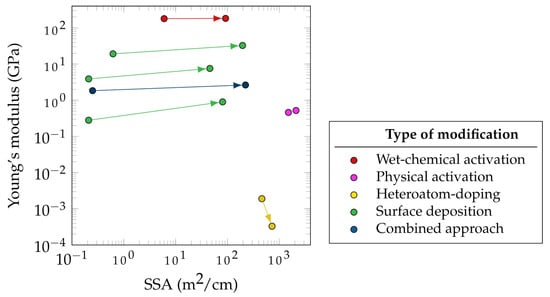
While the electrochemical performance of an SSC does not depend exclusively on the electrode porosity, the SSA has a strong correlation with specific capacitance as shown by Shirshova et al. [73][93]. In Figure 35, most of the presented modifications methods were applied to CF-based electrodes, while some were carried out for other carbon-based materials such as CNT fibers. This explains the comparatively higher SSA of modified CNT fibers. Figure 35 focuses more on demonstrating the improvement in the SSA rather than reporting the absolute values of post-treatment SSA.
It can be seen in Figure 35 that the highest SSA improvement (892 times) for carbon-based fibers is related to the CNT fibers that used sulfonated tetrafluoroethylene based fluoropolymer-copolymer as a pore-forming agent during fabrication (blue data points). An example of combined approaches for SSC electrode improvement is the combination of vertically aligned graphene and manganese dioxide [74][94] as well as the mixture of CAGs and the CPs using PEDOT [73][93]. Both methods resulted in a significant increase in specific capacitance, which can be attributed to the synergistic effects of both methods. Moreover, the deposition of either graphene or CAGs not only leads to more porosity, higher SSA, and hence higher specific double-layer capacitance, but also it improves the distribution of manganese dioxide and the CP, which then again contributes to the electrochemical performance by an increase in conductivity and pseudocapacitance. Hudak et al. used a combined approach in which they activated CFs and then deposited both CNTs and PANI. This method led to a 30-fold increase in the specific capacitance and an increase in the flexural strength of 27% with only a 7% decrease in the Young’s modulus [57][78].
Furthermore, a promising approach to increase the SSA has been the surface deposition of active materials (green markers), such as CAG (384 times) and Cu-Co-Se nanowires (316 times). The CAG surface deposition also resulted in the greatest increase in stiffness (3.2 times), followed by the deposition of GNPs, reaching values between 1.66 and 4.77 GPa (2.9 times).
There are other potentially promising combined approaches that have not been extensively studied for the use of CF electrodes in SSCs. These approaches include electrochemical and physical activation, heteroatom doping, and the introduction of pores during fabrication, in combination with the widely studied methods of surface deposition of active materials.
3. Current Collector
Theoretically, for some CF-based electrodes, a current collector might not be necessary. However, especially for long-fiber electrodes, the conductivity is very limited. In these cases, the deposition of ultra-thin metal coatings on the surface of the CF electrodes can help to increase the conductivity of the electrodes [23][42]. Using copper tape as a current collector, Javaid showed better electrochemical performance in SSCs [75][95]. Different materials can be used for each electrode, allowing for an asymmetric configuration of the SC. This can improve the working voltage and thus the power and energy densities of the SC [76][77][96,97]. However, the introduction of an additional copper tape results in additional weight and thus is contrary to the lightweight approach of SSCs (Figure 2b).
4. Electrolyte
The electrolyte of an SC acts as the distributor of charges between the two electrodes and therefore plays an important role [78][98]. The functionality of electrolytes requires a resistance against high voltages with a value of more than 3 V, high ionic conductivity, and a high chemical stability. All these properties influence the SC’s energy and power density. For SCs, a wide range of electrolytes have been extensively investigated including aqueous, organic, redox-type, solid-state, and semi-solid electrolytes and ionic liquids [79][99]. Aqueous electrolytes, such as KOH, Na2SO4, H2SO4 and NH4Cl solutions, offer higher ionic conductivity with values of approximately 1 S cm−1 and require a minimum pore size on the electrode surface. However, they are limited by small potentials, reaching values of approximately 1.2 V [80][81][100,101]. In contrast, organic electrolytes exhibit lower electrical conductivity, ranging from 10 to 60 mS cm−1 but compensate with a wider potential window from 2.5 to 2.7 V [56][77]. Ionic liquids possess exceptional properties including high thermal and chemical stability, low vapor pressure, a wide potential window, low flammability, and a conductivity of approximately 10 mS cm−1 [82][102].
For usage in structural supercapacitors, electrolytes also need to be able to carry and transfer mechanical loads to the CF electrodes and structural reinforcement layers which requires the use of solid-state electrolytes (SSE) [83][6]. The three main groups of SSEs include solid polymer electrolytes (SPE), inorganic solid electrolytes (ISE), and hybrid electrolytes (HE) [80][100]. SPEs are formed by combining a polymer matrix with a lithium salt, resulting in an ion-conducting material, while SPEs such as polyethylene oxide (PEO) exhibit good mechanical properties and show promising applicability for use as a matrix material. However, they have a high ion conductivity, low thermal stability, and low thermal conductivity at room temperature [84][103]. SPEs have the disadvantage of a high ionic conductivity at room temperature when the electrolyte is in a crystalline condition. At higher temperatures, the electrolyte switches to an amorphous state, which results in a higher ion conductivity due to the increasing dynamics of the amorphous chain and the less tortuous pathways for ion diffusion [85][104]. However, with an increase in the ratio of fillers to the host material, mechanical properties decrease [75][95]. ISEs are ceramics that conduct single ions through vacancies and interspaces [84][103]. Compared to SPEs, their electrochemical performance is thermally stable. The greatest disadvantage of ISEs is a high interface resistivity because of a low charge conductivity due to the lack of flexibility at the electrolyte/electrode interface. Additionally, the high porosity of ISEs make large-scale production difficult [80][100]. In order to counteract to the contrary features of SPEs and ISEs, HEs are developed by combining both groups of SSEs using (1) inorganic fillers in the polymer matrix, (2) layered SSEs consisting of inorganic and polymeric electrolytes, (3) organic-framework-reinforced electrolytes, or (4) bicontinuous ionic-liquid electrolytes [86][105].
4.1. Solid-State Electrolytes with Inorganic Fillers
Non-conducting passive inorganic fillers, such as SiO2, Al2O3, and TiO2 can be used to reduce the crystallization of the polymer matrix at room temperature. However, these passive nanofillers show low ionic conductivity with values below 10−4 S/cm. They exhibit adjustable characteristics and are inexpensive and comparatively simple to prepare. In addition, they increase the ionic conductivity of the host material by providing extra ion penetration pathways [87][106].
In contrast, conducting active inorganic fillers, such as lithium containing fillers, allow ionic flow, not only within the polymer chains but also along the filler’s pathways [87][106]. Therefore, active fillers have exceptional ionic conductivity reaching values higher than 10−3 S/cm, but they are difficult to synthesize [88][107]. Furthermore, rod-shaped active three-dimensional inorganic continuous fillers create fast ion-conducting pathways without crossing junctions along the vertically aligned interfaces of the three-dimensional frameworks, which enables higher ion conductivity [89][108]. Additionally, vertically aligned and continuous fillers prevent crystallization of the amorphous phases more effectively than regular inorganic fillers [90][109].
Another promising approach for SSEs is the introduction of self-healing properties by adding inorganic ions, such as KCl and H2SO4, which can exhibit self-healing properties. This behavior could counteract the mechanical degradation under mechanical loading and thus could represent an advantageous for SSEs. Thereby, self-healing is achieved due to the formation of hydrogen bonds [91][110]. To amplify the self-healing properties of the polymer, electrolytes must have high toughness and strength values to support huge deformation due to non-covalent interactions, such as hydrogen bonding [92][111], coordination [93][112], dynamic borate ester bonding [94][113], and host–guest interactions [95][114]. Testing on a flexible and self-healing supercapacitor based on activated carbon cloth showed outstanding flexibility, a composite capacitance retention of 88% over 10,000 cycles, and a good self-healing capability, with 80% capacitance retention after five cutting/healing cycles [96][115].
4.2. Layered Solid-State Electrolytes
A combination of layers of SPEs and ISEs allows for the adjustment of properties depending on the desired objectives and takes advantage of both electrolyte types to enhance the electrochemical properties of the composite as a whole [97][116]. This approach is of special interest, when trying to incorporate typical electrolyte systems from battery and supercapacitor research into multifunctional applications. Therefore, layered SSEs can be designed as double layers, with an ion-conducting polymer to reduce interfacial resistance with the anode [98][117], as a symmetrical sandwiched structure to improve the contact area between the ISE and the electrodes [99][118] or as an asymmetrical sandwich structure to fulfill multiple demands such as preventing lithium dendrite penetration while simultaneously providing good contact between the electrolyte and the electrodes [100][101][119,120]. Huo et al. [102][121] created a stackup of a polymer–ceramic composite, which achieved high ionic conductivity with values of 0.023 mS·cm−1, while having excellent flexibility and a good tensile strength of 11.3 MPa.
4.3. Solid-State Electrolytes with Metal–Organic Frameworks
Improving the electrochemical and mechanical properties of the polymer matrix with organic frameworks can be achieved by employing metal–organic frameworks (MOFs), covalent organic frameworks, and porous organic cages [84][103]. The enhancement is based on two main principles. The first principle is the containment of crystallization. Due to the Lewis-acidic sites on the MOFs interaction with the polymer chains in the polymer matrix, crystallization can be prevented to a large extent [103][122]. For the second principle, the incorporation of a highly conductive liquid electrolyte onto the porous surface of the organic frameworks forms a quasi-solid electrolyte, which creates further ion-conducting pathways along the framework [87][106]. A study by Wang et al. [104][123] showed a five-fold increase in ionic conductivity and better contact with the electrode than that of the SSE without MOF-related materials. However, mechanical tests on MOF electrolytes are currently rare, making it difficult to quantify their benefit to the overall SSC performance.
4.4. Solid State Electrolytes with Bicontinuous Phase Structure
Bicontinuous phase structures are a way to create polymers that can conduct ions and bear loads at the same time. This is achieved by combining two materials with separate load-bearing and ion conductive functionality [105][124], which is often performed by synthesizing the polymer electrolyte. This yields a Young’s modulus of approximately 2.77 GPa, a tensile strength of 80 MPa [106][125], and an ionic conductivity of 10mS·cm−1 in the presence of an ionic liquid [82][102]. The presence of an ionic liquid is necessary to form a cross-linking structure in which the ionic liquid is deeply incorporated [107][126]. Ionic liquids alone cannot transmit any mechanical loads and therefore they reduce the mechanical properties [108][109][127,128] (Figure 46). As a result, it is inherently difficult to strike a balance where the improvement of one property is at the expense of the other.
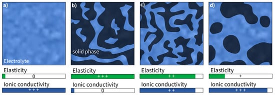
Figure 46. Schematic illustration and assessment of Young’s modulus and ionic conductivity of (a) pure liquid electrolyte and (b–d) different kinds of bicontinuous phase structures (assessment of properties: 0—none, +—good, ++—high, +++—very high).
4.5. Summary of Different Types of Solid-State Electrolytes
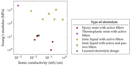
Figure 57 summarizes the electrochemical and mechanical properties of different SSEs which have been used in SSCs. It has to be noted that the presented parameters, such as the ionic conductivity, depended on several factors. The data from literature do not follow unified standards. Therefore, some standards have been proposed in the literature for evaluating these properties [110][129]. According to Wang et al., SSEs with ionic conductivities below 1 mS·cm−1 are not applicable for SSCs [111][130]. Based on this assessment, none of the observed SSEs that have been reviewed fulfill this requirement. Of the reported SSEs, the highest ionic conductivity is 0.8 mS·cm−1, measured for an ionic liquid with active fillers, created by Shirshova et al. [105][124].
Furthermore, the mechanical properties of SSEs are often significantly lower compared to those of pure epoxy resin. This results in a Young’s modulus of 3.35 GPa and a tensile strength of 86.04 MPa for a CNT/epoxy nanocomposite [114][133].
Javaid showed that the use of different active fillers such as TBAPF6, LiTFSI, NaClO4 and EMITFSI would lead to different ionic conductivities. A similar observation was made by Wang et al., who dissolved a lithium salt in the thermoplastic polymer polyvinylidene fluoride and then mixed it with epoxy resin. A higher epoxy content leads to lower ionic conductivity but higher mechanical properties. Interestingly, when the thermoplastic polymer was mixed with the active filler LiTf and no epoxy was added, the best mechanical and electrochemical properties were observed, suggesting the potential use of thermoplastic electrolytes for SSEs [115][134]. This approach was further studied by Joyal et al., who created a single-phase solid polymer electrolyte by mixing the thermoplastic polymer polyethylene terephthalate with the lithium salt LiClO4 [112][131], achieving the highest reported Young’s modulus of 2100 MPa but also the lowest ionic conductivity of 1 mS·cm−1. However, the use of thermoplastic polymers as a base for SSEs does not only suggest potential in terms of mechanical and electrochemical properties but also in terms of processability. This could open new ways of fabrication routes for SSCs. Another promising method with high mechanical properties are the use of ionic liquid with active and passive fillers. As an example, DGEBA/LiTFSI/BMIM-TFSI/Al2O4 (5 vol%) was reported to achieve 1000 GPa and approximately 0.29 mS·cm−1.
The relatively good properties of electrolytes with ionic liquid and active fillers make this approach the most common method of SSE synthesis for SSC application [105][116][124,135]. This method allows the active filler to completely dissolve in an ionic liquid such as 1-ethyl-3-methylimidazolium bis(trifluoromethylsulfonyl)imide (EMIM-TFSI), which is then mixed with the epoxy resin. This approach leads to the creation of porous microstructures providing ion path channels to further increase ion conductivity. To additionally increase the mechanical properties of ionic liquid-based SSEs without sacrificing ionic conductivity, Kwon et al. incorporated Al2O3 nanowires as passive fillers. Due to the Lewis-acidic conditions of those incorporated Al2O3 nanowires, not only the Young’s modulus but also the ion conductivity was enhanced [113][132].
5. Separator
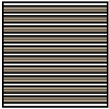
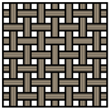
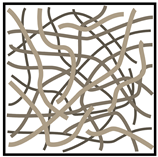
An SC’s separator is placed between the two electrodes and prevents electron flow, blocking a short circuit. Therefore, it must provide both high ionic conductivity and mechanical stability [117][136]. Consequently, in load- carrying SSEs, a separator is essentially not required. However, due to safety concerns, they might still be included in the design. Further important properties in separators are their chemical and thermal stability, low density, corrosion resistance as well as their low cost and availability [83][6]. Additionally, optimal porosity and minimal thickness for good electrolyte storage and high electrolyte uptake are often linked to high ionic conductivity [83][6]. The most widely used separator material in SSC is glass fiber. Other promising separators used in conventional SCs are polymers, ceramics, and cellulose [118][137] (see Figure 68).
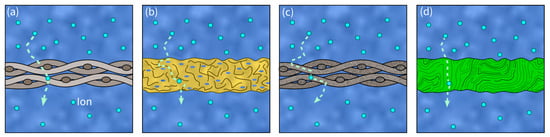
Figure 68. Visualization of different separator materials and ion transport paths (dashed arrows): (a) glass fiber separator, (b) polymer separator, (c) ceramic separator, (d) cellulose separator.