Your browser does not fully support modern features. Please upgrade for a smoother experience.
Please note this is a comparison between Version 1 by Eduardo Tomanik and Version 2 by Rita Xu.
The tribological performance of a thermal sprayed, mirror-like surface with localized protuberances was investigated through tribotests and computational simulation. A composite coating with a 410L steel matrix and M2 tool steel hard particles was applied by the cold spray process as a bore coating for combustion engines. The presence of protuberances promoted the quick formation of an antifriction tribofilm when tested with an SAE 0W-16 containing ZDDP and MoDTC, which significantly reduced the asperity friction in comparison to the conventional engine coated bores in reciprocating tribological tests.
- friction
- surface texture
- lubricant additive
1. Background
Engine friction losses represent one-third of passenger car fuel consumption and CO2 emissions [1][2][1,2], around 50% of which are due to piston friction. The tribological system composed by the piston rings, the cylinder bore and the oil, as a reciprocating system with variable loads and temperatures, faces both boundary/mixed and hydrodynamic lubrication regimes. Indeed, the piston-bore sliding speed varies all along the stroke and depends on the engine regime (rpms). For a given rpm, the stroke can be divided in three parts: two zones near the top and bottom dead centers, where the speed is low and the regime is boundary/mixed, and the middle part of the stroke, where the speed is higher and the regime is hydrodynamic. At different rpms, the same division is still valid, but the extension of the three zones varies; at higher rpms, the hydrodynamic zone is larger than at lower rpms. As friction losses occur only after combustion, the corresponding 10% of fuel energy represents approx. 25% of fuel consumption. Combustion efficiency is ~40%, and the 10% (fuel energy) of friction losses occurs only after combustion, so in terms of fuel consumption, friction losses are 10/40 = 25%. See details in [3].
-
The use of materials/coatings with a low friction coefficient;
-
Surface finish and/or texturing, especially by optimization using computer models and detailed topographic characterizations;
-
Low-viscosity oils and improved friction-modifying additives.
In a lubricated tribological contact, even in a hydrodynamic regime in which the parts are not directly in contact, the surface texture is very important to promote good tribological performance. The use of a surface with dimples has been widely studied for that purpose. When the void ratio created by the dimples is high, the coefficient of friction generally increases under boundary and mixed regimes due to higher contact stress [5]. On the other hand, in a hydrodynamic regime, the surface with dimples tested in [6] reduced the friction coefficient by up to 35% thanks to a lower oil shear rate.
Oil formulation composition has a major influence on friction properties. First, the viscosity plays an important role. Oils with high viscosity values reduce friction and wear in the boundary and mixed regimes but increase them in hydrodynamic regimes [7]. For this reason, low-viscosity oils are increasingly used in actual engines. The wear resistance in the mixed/boundary regime zones of the stroke is assured in this case by oil additives. Zinc dialkyldithiophosphate (ZDDP) has been widely used and studied as an antiwear additive. During friction, it reacts to create a thick tribofilm, protecting the surface from wear. As a drawback, it increases the coefficient of friction [8]. Molybdenum dialkyldithiocarbamate (MoDTC) is a well-known friction modifier that reacts in the contact areas to form MoS2 solid lubricant. MoS2 reduces the coefficient of friction but not the wear [9]. When ZDDP and MoDTC are combined, both a low friction coefficient and good wear protection can be obtained [10].
Fully formulated engine oils containing ZDDP and MoDTC among their additives show an interesting interplay with surface textures. Additives generally react first on asperities and then accumulate inside dimples or grooves to form a continuous protective film [11][12][11,12].
Different thermal spray technologies have been used to apply coatings onto engine cylinder bores, to reduce the interbore distance, to allow for easy cooling and to reduce friction losses using mirror-like surfaces. In comparison with cast materials, thermal sprayed coatings are characterized by a non-uniform microstructure due to the presence of pores and oxides, also inducing a non-homogenous hardness. The manufacture of these coatings, including two-way interactions of thermal spray and mechanical finishing, is subject to challenges with respect to effective and efficient processes [13][14][13,14].
2. Mirror-like Coated Bores Produced by Thermal Spraying
Mirror-like coated bores used in recent combustion engines are much smoother than gray cast iron blocks or iron cast sleeves on aluminum blocks. See Figure 1 and Figure 2. As an example, Figure 2 illustrates the topography of two engine cylinder bores: a plateau-honed gray cast iron bore and a mirror-like coated bore. The second is significantly smoother than the first, with a Sa value eight times lower than that of the former. Due to their very low roughness, mirror-like coated bores are very effective in reducing engine friction losses at low and moderate sliding speeds. However, as the sliding speed increases and hydrodynamic losses dominate, as shown in Figure 3, such benefit is reduced and becomes negligible at high rpms.
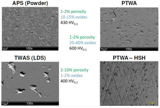
Figure 1. Some of the coated bore variants in production.
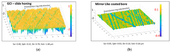
Figure 2. Topography and roughness of two production engine cylinder bores: (a) gray cast iron, plateau-honed bore; (b) mirror-like coated bore.
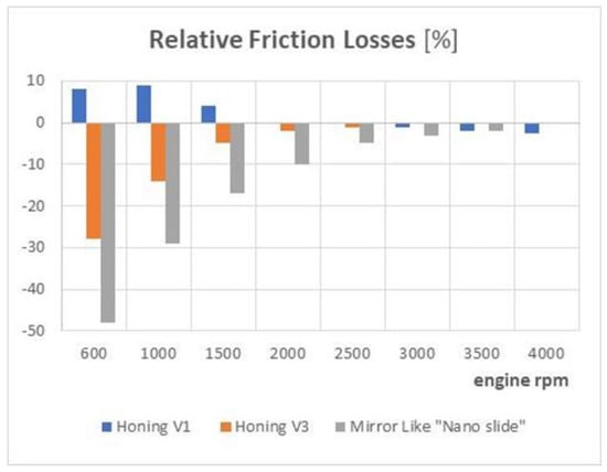
Figure 3. Relative friction losses of different engine cylinder bores.
A composite coating made with a 410L stainless steel matrix and hard M2 tool steel reinforcements was applied by the cold spray process. Two commercially available steel powders produced by Sandvik Osprey Ltd. were mixed in a volume ratio of 80/20, respectively. Their particle size distribution, as provided by the supplier, was +32–10 µm. The cold spray equipment used was 5/11 from Impact Innovations GmbH, equipped with an internal diameter coating device with nitrogen as the principal gas, a pressure of 5 MPa and a temperature of 900 °C. The stand-off distance and powder feeder rotation speed were set at 5 mm and 8 rpm, respectively. They were sprayed to form the composite coating directly onto 10 mm-thick laminated aluminum 6060 plates with dimensions of 65 by 40 mm.
Thanks to the local inhomogeneity of the coating hardness induced by the presence of M2 steel particles, the surface finishing resulted in a textured topography whereby the harder M2 particles became protuberant. It was then demonstrated that friction on that surface with protuberances promoted the formation of a thick tribofilm all around the protuberances, leading to a very low coefficient of friction (<0.04) and negligible wear in the mixed/boundary regime. In the present article, the tribological behavior of the same surface with protuberances was studied under a hydrodynamic regime. To do so, a deterministic computer model was applied. A reciprocating computer model was then used to predict the piston ring friction losses.
3. Topographical Characterization of Textured Surfaces
The use of localized texturing creates the need for more complex surface quantification. A mirror-like surface with localized texturing cannot be described only by the usual statistical roughness parameters such as Sa, Spk, etc. Mirror-like and textured surfaces are mostly composed of a very smooth topography, with a few relevant topographic features. Special care is also need for waviness filtering. Few but deep localized features can evade simpler waviness filters. Therefore, classical statistically based models may fail to reproduce the actual application, as discussed in [15][17]. Several standards deal with this statistical bias. For surfaces with localized features such as dimples or protuberances the norm DIN EN ISO 8785: 10/1999 suggests that surface imperfections that often represent a minor portion of the surface (<<20%) can be used as a reference. According to DIN EN ISO 21920-2:12/2022, all the 31 local surface imperfections described in DIN EN ISO 8785 are to be explicitly excluded from the amplitude calculation, Abbott and hybrid parameters of DIN EN ISO 25178-2: 02/2020. This needs to be considered when calculating Sa, Spk, Sk and Svk to avoid outliers (local phenomena) adulterating the meaning of the roughness parameters. However, excluding the localized features results in a dilemma with respect to how to properly characterize and quantify, for example, dimples and protuberances. This topic is outside the scope of the current paper but is briefly discussed in Appendix A and in more detail in [14].
A 13Mn6 LDS coating, which is currently applied in the production of engines, was used as a reference case for comparison. This coating shows upstanding material as described in DE 10 2012 002 766 B4 as Deckel-Ölvolumen (“cap oil volume”) [16][18] (hereafter called protuberance) at comparatively high volumetric expansions. This kind of upstanding material also is observed around pores and grooves in the finishing process of similar specimens, along with unwelcomed phenomena of seizure in engine tests [17][19]. The origin of the surface material integrity issues can be explained by spray and layer build-up processes (large, porous holes and lower intermetallic connections). The relatively less impact of the spray quenching process in cold-sprayed finished 410L seems to result in only small pores and homogeneous finishing abrasion without upstanding material. The 20% M2 addition in the third sample results in a comparatively finer and more even distribution of protuberances (micro plateaus) compared to the 13Mn6LDS due to the surface finishing process. Indeed, the hardness difference between the 410L and the reinforcing M2 particles results in different abrasion rates so that in this case, the quantity of upstanding material is controlled by material composition.
4. Computer Models for Piston Ring and Cylinder Bores
As mentioned before, as the major source of engine friction, the piston system is one of the main subjects for the development of low-friction technologies. As a reciprocating system, the piston assembly can operate in boundary, mixed and hydrodynamic lubrication regimes. The hydrodynamic regime is more relevant for power losses and fuel consumption since it generally occurs at higher speeds. Figure 4 summarizes different approaches for simulating the lubrication behavior of a piston ring–cylinder bore system [15][17].
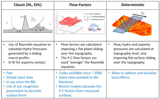
Figure 4. Computer models for a mixed lubricating regime.
-
Classical Reynolds equation and stochastic asperity contact models: The hydrodynamic pressures are calculated using the Reynolds equation, considering the ring kinematics, the running profile and the physical properties of the lubricant. Under mixed lubrication conditions, where the oil film thickness is not enough to completely separate the surfaces, a statistically based rough contact model (usually the Greenwood–Williamson or Greenwood–Tripp model) is adopted to calculate the asperity contact pressures. This approach fails to account for the hydrodynamic pressures generated by the surface roughness, and it predicts zero hydrodynamic pressures for flat, parallel surfaces (e.g., oil control ring outer lands).
-
Average Reynolds equation and flow factors: The previous approach can be improved for mixed lubrication analysis by incorporating the effect of surface roughness on lubrication through the adoption of averaging flow methods. In these cases, the influence of roughness (microscale) is considered by utilizing averaging parameters (flow factors) introduced in the Reynolds equation, which is then solved considering the macroscopic geometry of the contacting surfaces. The most common averaging method used for piston ring simulation is the Patir–Cheng average flow model, which provides a modified average Reynolds equation.
-
Deterministic simulations: In this approach, the effect of surface topography is directly considered for the simulation of a mixed lubrication regime. The hydrodynamic and asperity contact problems are solved simultaneously in the same numerical framework. Due to the high CPU efforts, the most common approach is to segment the surface topography into small slices and then solve the coupled hydrodynamic and asperity contact problems in a quasistatic manner by imposing different separations between each slice and a rigid plane. Alternatively, fully deterministic simulations can be employed such that no segmentation is applied beforehand, and the surface separations are calculated based on the instantaneous load equilibrium.