Your browser does not fully support modern features. Please upgrade for a smoother experience.
Please note this is a comparison between Version 1 by Diogo M.F. Santos and Version 2 by Camila Xu.
The concept of underground hydrogen storage (UHS) is less known than its natural gas counterpart, which is expected due to its less significant role in the past. Despite this, the insights gained with natural gas can be applied to hydrogen storage due to the shared cavern design and operation.
- green hydrogen
- underground hydrogen storage
- geological structures
1. Introduction
The past decades have seen an increase in the share of renewable energy sources in the energy mix, showing the importance of decarbonizing the energy sector. However, their intermittent nature poses a challenge when aiming for a successful transition. While mechanical storage technologies like pumped hydro and compressed-air energy storage have the potential to mitigate the fluctuations in renewable energy sources, the limited storage density of water and compressed air hinders their large-scale implementation, particularly for long-term seasonal storage. It has become generally accepted that the surplus of renewable energy should be used to power water electrolyzers and produce green hydrogen, which fits into the well-known Power-to-X technologies.
Besides its numerous uses, such as propelling fuel, feedstock for fertilizer industry and oil refining, hydrogen is recognized as a secondary source of energy, and an essential energy carrier [1]. In contrast to mechanical energy storage, chemical energy carriers (like hydrogen or natural gas) offer an energy density approximately 100 times higher than compressed-air energy storage for the same storage volume. The combustion of 1 m3 of hydrogen produces 12.7 MJ of energy, although it is three times lower than that from methane combustion (40 MJ). Hydrogen is not considered an energy source because the energy needed to create it is more than the one it produces when consumed. However, converting it to heat or electricity is easy, as it is an efficient energy carrier because of its transporting and storing capabilities. As an example, the loss during energy transportation by a gaseous carrier (<0.1%) is much lower than that using the power network (8%) [1]. Thus, hydrogen storage is directly related to energy storage.
It should be emphasized that not all hydrogen is green. In fact, hydrogen can be produced through different processes, including thermochemical, electrochemical, and biological processes, or direct solar water splitting. Most of the current production comes from fossil fuels (grey, black, and brown hydrogen). With the expected increase in green hydrogen production, efficient storage methods will be required, and underground hydrogen storage (UHS) systems might present a crucial solution. It is important to acknowledge how large the storage capacity needs to be (hydrogen has a lower energy density when compared to methane). Underground formations, including depleted gas fields, aquifers, and salt caverns, can satisfy such volumes. Pipelines or vessels can also be considered viable options. Still, underground salt caverns are more favorable for seasonal storage than above-ground storage technologies [2]. Other storage options, such as abandoned coal mines, lined hard rock caverns, and refrigerated mined caverns, are expected to become more popular as the demand for storage grows, especially in regions where depleted reservoirs, aquifers, and salt deposits are not available [1].
Besides satisfying the storage capacity, the structures mentioned present a safer environment than above-ground options mainly because of the absence of atmospheric oxygen; the mixture of hydrogen and this gas is unstable even in small concentrations. In addition, large storage volumes make operations economically viable and enable an economic threshold.
Figure 1 shows, at a generic location, how the surplus energy that renewable sources have above ground could be used to produce hydrogen and store it underground (the general idea of UHS). It also reflects an essential aspect of the technology: the depths at which the storage structures are usually found. The depleted hydrocarbon reservoirs (mainly depleted gas fields) are the type of structures that are the deepest on the earth’s crust. This involves challenging drilling, although most of the infrastructure used in the past to operate the reservoirs can be reused. Closer to the surface, there are formations like aquifers and salt caverns. Their specific depths will influence their storage capacities. Finally, the structures closer to the surface are rock caverns, which are still behind in the UHS race, as the cost of storage per kilogram of hydrogen is more than double when compared to the other three formations mentioned [1], mainly due to the lack of a natural impermeable layer (or seal).
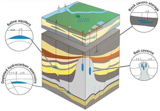
Figure 1.
Geological structures suitable for underground hydrogen storage (UHS) [3].
2. Geological Structures for Underground Hydrogen Storage and Relevant Parameters
The concept of underground hydrogen storage (UHS) is less known than its natural gas counterpart, which is expected due to its less significant role in the past. Despite this, the insights gained with natural gas can be applied to hydrogen storage due to the shared cavern design and operation [2]. Thus, the current challenge for UHS technology developers is to address the differences, particularly in materials, access wells, cavern heads, and transmission infrastructure. Natural gas storage in an underground formation was first achieved in 1915 in a partially depleted gas field in Ontario, Canada. Since then, much experience has been gained in almost every aspect that UHS englobes, such as site specifications, storage techniques, monitoring, life cycle costs, and economic viability.
Geological sites suitable for the underground storage of gases can be classified into two main categories: (a) porous media, in which hydrogen is stored within the pore space of sandstones or carbonate formations, and (b) cavern storage, in which hydrogen is contained within excavated or solution-mined cavities in dense rock formations. The properties of the gas to be stored play a crucial role in the success of the storage operations. Each geological formation presents unique challenges, requiring an understanding of the specific parameters for each type.
2.1. Depleted Oil and Gas Reservoirs
Hydrocarbon reservoirs are typically porous and permeable rock formations like sandstones or carbonates. The hydrocarbons are trapped within the reservoir by impermeable rocks or seals, forming a subsurface reservoir that can be exploited through drilling and production techniques. After this, the structure remains empty and can be used for UHS. According to Kanaani et al. [4], depleted hydrocarbon reservoirs present the best choice for large-scale UHS thanks to their known geological structure, the proper compactness and integrity of the source rock, and the pre-existence of surface facilities. Furthermore, the tightness of the caprocks of depleted gas reservoirs has also been proven. However, transforming the depleted reservoir into a UHS site requires comprehensive studies. For example, the remaining gas on gas fields is advantageous because it can act as cushion gas. Conversely, it can be a disadvantage if this remaining gas reduces the hydrogen purity. In the case of residual oil, the chances of chemical reactions increase, and hydrogen may turn into (for example) methane.
Actual underground gas storage operations have proven that the storage process needs cushion gas (or base gas). N
2
, CH
4
, or CO
2
, among others, can work as cushion gases. This requirement comes from the need to maintain the reservoir pressure, as hydrogen is being withdrawn. This gas is also important because it accompanies the hydrogen being produced, consequently affecting the quality of the hydrogen outflow. This highlights the urge to implement several purification steps for the hydrogen retrieval process, which are costly [4].
Ultimately, the main advantage of depleted reservoirs is the economic threshold that previous studies and site exploration present regarding the lifespan of such assets. UHS brings back the possibility of deep and ultra-deep oil and gas well drilling, as the well will generate profits from the oil and/or gas production and, later, from the UHS once the reservoir reaches its oil or gas production lifespan. This theoretical “second life” of the reservoir would begin after the point marked as abandonment in
Figure 2,
stretching the economic limit, which must be considered in the project’s initial investment.
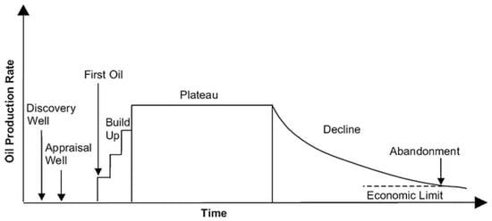
Figure 2. Conventional production profile of an oil field. Reprinted from [5] with permission from Springer Nature.
2.2. Aquifers
These formations are porous and permeable media full of pore spaces filled with fresh or saline water. Aquifers are distributed worldwide, which makes them a logical choice for UHS. Several reported cases in the literature on the use of aquifers for gas storage demonstrate their potential for hosting hydrogen. They accumulate the majority of the total natural gas storage in the subsurface. However, to date, no pure hydrogen storage has been reported. Gas storage with a composition of around 50% H
2
and 50% CH
As mentioned, porous media use the pore space to store gas, but this does not imply that all porous media are suitable for UHS. Suitable aquifers may have a geology similar to depleted gas reservoirs [7]. Another condition preferable (if not necessary), that not all aquifers count with, is having an impermeable layer to inhibit the migration of the stored gas. This condition is accomplished via hydrocarbon reservoirs, as they are found deeper in the earth’s crust. However, aquifers may not have been formed under the same critical conditions; consequently, some lack this characteristic. A downside related to this is the often more expensive development when compared to depleted reservoirs due to the uncertain geology and lack of infrastructure. Geologic characteristics are not well known, and data must be acquired to determine whether the formation can trap and seal the gas.
Other expenses in the construction of these UHS sites, besides exploration wells, include the construction of above-ground facilities, injection and extraction wells and circuits, and a system to dehydrate the hydrogen, given the presence of water in the structure. Not everything is disadvantageous with these formations; they present several positive points. The ease of finding them pretty much everywhere and the increased pressure due to the difference in density between the liquid and gas phases are the main benefits that make them an attractive option. Regarding this last characteristic, the overpressure of porous media could make up for faster hydrogen flow rates, higher recovery ratios, and, hence, fewer losses at the expense of a larger investment. Finding the proper site with a large storage volume could compensate for the additional costs for exploration and dehydration systems due to the higher operational efficiency.
Still, aquifers have a long way to go, with many abiotic and mineral reactions to consider in each project. Shallow extraction could minimize this, but the impermeable layer must exist to avoid the losses. Aquifers are a developing technology for UHS that will keep scaling in the coming years [6].
2.3. Salt Caverns
Salt caverns are currently considered to offer the most promising underground storage option owing to their low cushion gas requirement, the large sealing capacity of rock salt, and the inert nature of salt structures, preventing the contamination of the stored hydrogen. The geometry of these structures is usually cylindrical. Salt caverns are artificial pits in thick underground salt deposits made from the surface by introducing water into a well in the salt rock, a process termed solution mining. Considering the requirements (and technical scope), they can be made up to 2000 m deep and have a volume of 1 Mm
3
, a height between 300 and 500 m, and around a 50–100 m diameter, enabling them to store gas in massive quantities.
Figure 3
illustrates these structures based on sonar measurements, as well as a general layout of the depths at which they can be built, showing it is possible to have a shallower storage reservoir when compared to oil and gas fields.
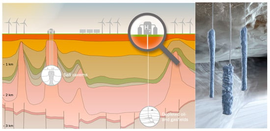
Figure 3.
Schematic illustration of the depths of salt caverns and depleted oil and gas fields (
left
). Representation of three salt caverns surrounded by salt, based on sonar measurements (
right
The main parameter determining their capacity is the depth. A higher cavern depth leads to more pressure and, in turn, more compressed gas, while lower amounts of cushion gas are needed at a lower depth, which helps reduce the operation’s cost. Usually, for UHS in salt caverns, the pressure during the process ranges from 30 to 80% of the lithostatic pressure (i.e., the pressure imposed on a stratigraphic layer by the weight of overlying layers of material) [1][2]. The specific geological settings, including tightness, the praiseworthy mechanical properties of salt, and its low reactance, make salt caverns practical for UHS. Additionally, the high saline environment restricts the hydrogen consumption by microbes.
Other advantages of salt cavern storage options include flexible operations, high injection rates, and faster withdrawal cycles. The viscoplastic characteristics of evaporitic rocks contribute to their better sealing function and, taking into account that salt caverns are mechanically stable, make the injection–withdrawal process more flexible and adequate for medium- or short-term storage.
From the economic point of view, the total cost to create salt chambers is lower than for other underground formations and less than for aquifers and depleted oil and gas reservoirs, as all these processes are built from the surface through a single well. This well use during the injection and withdrawal periods makes salt cavern storage facilities easy to manage, allowing for the gas to be injected and extracted several times per year. The actual implementation of the structures in gas storage (other than hydrogen) proves that these are ideal for keeping peak-time gas reserves.
The extensive experience gained by projects worldwide allows salt cavern developments to have as many as sixty-three underground formations. This was achieved in Jintan, Jiangsu province, in China, where this facility has served as an underground gas storage (UGS) site since 2007 [9].
These characteristics endow salt caverns with long-term stability. Experts have concluded that these deep geological formations are the safest and most economically viable for implementing UHS, storing large volumes of electrical energy after conversion into hydrogen or methane. Their recommendation is mostly due to the many decades of positive operating experience as underground storage reservoirs for natural gas [10].
2.4. Parameters
It is crucial to characterize the sites for UHS and to have a solid reference for better results when developing them. The parameters presented while explaining each geological structure’s advantages and disadvantages should be organized and fulfill a standard. To date, there is not an organization that regulates UHS, nor a particular reference to look at. Thus, this subsection discusses the most influential parameters falling into three categories: the solid properties, fluid properties, and solid–fluid (and fluid–fluid) interactions.
The solid properties of the storage medium are crucial factors that influence the UHS storage capacity, storage effectiveness, and containment security. Among them, absolute permeability (
The main parameter determining their capacity is the depth. A higher cavern depth leads to more pressure and, in turn, more compressed gas, while lower amounts of cushion gas are needed at a lower depth, which helps reduce the operation’s cost. Usually, for UHS in salt caverns, the pressure during the process ranges from 30 to 80% of the lithostatic pressure (i.e., the pressure imposed on a stratigraphic layer by the weight of overlying layers of material) [1,2]. The specific geological settings, including tightness, the praiseworthy mechanical properties of salt, and its low reactance, make salt caverns practical for UHS. Additionally, the high saline environment restricts the hydrogen consumption by microbes.
Other advantages of salt cavern storage options include flexible operations, high injection rates, and faster withdrawal cycles. The viscoplastic characteristics of evaporitic rocks contribute to their better sealing function and, taking into account that salt caverns are mechanically stable, make the injection–withdrawal process more flexible and adequate for medium- or short-term storage.
From the economic point of view, the total cost to create salt chambers is lower than for other underground formations and less than for aquifers and depleted oil and gas reservoirs, as all these processes are built from the surface through a single well. This well use during the injection and withdrawal periods makes salt cavern storage facilities easy to manage, allowing for the gas to be injected and extracted several times per year. The actual implementation of the structures in gas storage (other than hydrogen) proves that these are ideal for keeping peak-time gas reserves.
The extensive experience gained by projects worldwide allows salt cavern developments to have as many as sixty-three underground formations. This was achieved in Jintan, Jiangsu province, in China, where this facility has served as an underground gas storage (UGS) site since 2007 [9].
These characteristics endow salt caverns with long-term stability. Experts have concluded that these deep geological formations are the safest and most economically viable for implementing UHS, storing large volumes of electrical energy after conversion into hydrogen or methane. Their recommendation is mostly due to the many decades of positive operating experience as underground storage reservoirs for natural gas [10].
2.4. Parameters
It is crucial to characterize the sites for UHS and to have a solid reference for better results when developing them. The parameters presented while explaining each geological structure’s advantages and disadvantages should be organized and fulfill a standard. To date, there is not an organization that regulates UHS, nor a particular reference to look at. Thus, this subsection discusses the most influential parameters falling into three categories: the solid properties, fluid properties, and solid–fluid (and fluid–fluid) interactions.
The solid properties of the storage medium are crucial factors that influence the UHS storage capacity, storage effectiveness, and containment security. Among them, absolute permeability (
𝑘𝑎) is the ability of a porous medium to transmit fluid (when the porous medium is 100% saturated by this fluid). The effective porosity (
) is the ability of a porous medium to transmit fluid (when the porous medium is 100% saturated by this fluid). The effective porosity (
𝜙effective
) is defined as the ratio of the connected pore volume to the bulk volume, which determines the maximum storage capacity. The effective stress (
𝜎effective) is defined as the difference between the overburden (or overcharge) pressure and pore pressure [11].
The fluid properties are also critical parameters that strongly influence the UHS effectiveness and safety. Because these were previously discussed, they are omitted in this subsection. Nevertheless, these parameters should always be considered and reviewed in detail for each case. Some chemical reactions may or may not occur depending on the particular site and location.
The last category proposed is the solid–fluid and fluid–fluid interactions. Although these are related to the solid and fluid properties, the interactions fall into a separate category because they characterize different aspects of UHS: fluid distribution, fluid migration, gas adsorption, chemical reactions, and reactive transport. The interactions require work on their own, as they follow complex mathematical models, and computational calculations are the only way to analyze the data. Although some preliminary work has been completed, and some data are available, it is clear that this category needs to improve its specifications to succeed with the plan for standardizing UHS. The following parameters in this category are mentioned as areas to cover and develop in future investigations and projects: the wettability, interfacial tension, capillary pressure and capillary forces, relative permeability, mobility ratio, absorption–desorption, inorganic reactions, and biochemical reactions. Although similar to other gas storage (e.g., the natural gas case), UHS does not share the same reference values for this last category. Therefore, extrapolation from these different scenarios must be avoided [11].
) is defined as the difference between the overburden (or overcharge) pressure and pore pressure [11].
The fluid properties are also critical parameters that strongly influence the UHS effectiveness and safety. Because these were previously discussed, they are omitted in this subsection. Nevertheless, these parameters should always be considered and reviewed in detail for each case. Some chemical reactions may or may not occur depending on the particular site and location.
The last category proposed is the solid–fluid and fluid–fluid interactions. Although these are related to the solid and fluid properties, the interactions fall into a separate category because they characterize different aspects of UHS: fluid distribution, fluid migration, gas adsorption, chemical reactions, and reactive transport. The interactions require work on their own, as they follow complex mathematical models, and computational calculations are the only way to analyze the data. Although some preliminary work has been completed, and some data are available, it is clear that this category needs to improve its specifications to succeed with the plan for standardizing UHS. The following parameters in this category are mentioned as areas to cover and develop in future investigations and projects: the wettability, interfacial tension, capillary pressure and capillary forces, relative permeability, mobility ratio, absorption–desorption, inorganic reactions, and biochemical reactions. Although similar to other gas storage (e.g., the natural gas case), UHS does not share the same reference values for this last category. Therefore, extrapolation from these different scenarios must be avoided [11].
Figure 4
shows how each type of geological structure suitable for UHS performs for some relevant operational parameters.
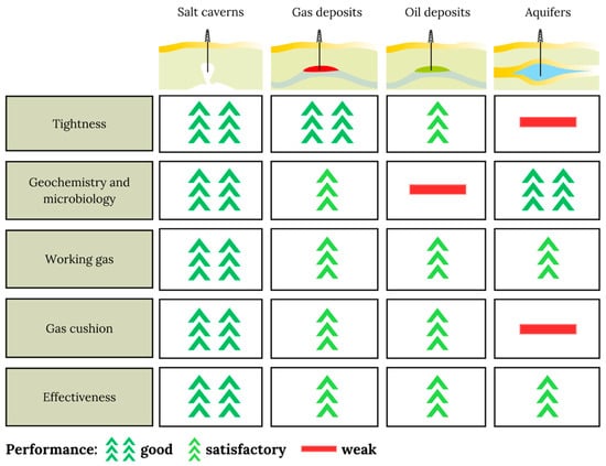
Figure 4. Comparison of selected operational parameters of geological structures suitable for UHS.
2.5. Seasonal Storage
Seasonal energy storage refers to capturing and storing energy during excess supply or low demand, typically during certain seasons. The stored energy is used when the demand is higher, or when the supply is limited. It involves storing energy for an extended period, usually spanning months, to address the seasonal variations in energy production and consumption. This energy consumption varies with the demand, depending on daily and seasonal changes or emergencies, while the energy production is usually constant. The excess electricity produced is converted to hydrogen to regulate these fluctuations and is temporarily stored and used later when the consumption exceeds the production, a process known as Power-to-Power [1]. Energy storage will play a key role in providing the required system security, flexibility, and adequacy in the future integration of hydrogen into the energy system. Stability refers to the response to short and fast fluctuations in the power system. Flexibility corresponds to the response to load and supply changes up to the seasonal timescale. As for the ability to adjust to long-term trends and emergencies, this is called adequacy. Supply and demand patterns influence the energy system on different timescales, demanding different solutions. Therefore, more significant energy storage deployment is predicted at these different scales. As seen in
Figure 5
, the need for a portfolio of energy storage solutions that exploit the advantages of each storage technology and altogether deliver the needed systems services is clear [8].
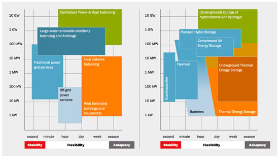
Figure 5.
Energy system services and storage options mapped according to their power and relevant timescales (charging and discharging). The color indicates the infrastructure system in which it is implemented: (blue: electricity grids; green: gas infrastructure; orange: heat networks) [8].
Furthermore, hydrogen production via water electrolysis using surplus wind energy with its high-energy yield ratio can enable a wider utilization of wind energy, offset costs, and balance supply variability. As noted, this leads to heavy short-term fluctuations in electricity prices and subsequently to short-term fluctuations in mainly the hydrogen supply from electrolysis, and, therefore, to a need for absorbing this produced hydrogen in storage facilities. Significant experience has been gained through a number of small-scale renewable hydrogen systems [12]. UHS offers a feasible clean energy storage option, leaving free surface area to install more capacity (wind, solar, or other technologies) and creating massive energy reserves for future long-term trends and development.
Considering the use of surplus energy (mostly from wind and solar energy production) for green hydrogen production through electrolysis and then for its underground storage, the energy industry and others are awaiting information on the possibilities in this regard [13].
Figure 6 helps illustrate how UHS could help compensate for peak demands and make up for seasonal patterns. Looking at the red line on each graph, one can observe how the demand stays more or less constant with its respective peaks compared to the solar and wind resource variability. Thus, intermittent renewable electricity output is a problem that can be solved by dealing with another one: the excess power generated by wind and solar parks when the demand is low. This extra energy needs to be stored so that it can be made available during peak periods. This can be accomplished by using this surplus electricity to split water into oxygen and hydrogen through electrolysis. Electricity is then converted into hydrogen as molecules that can be stored. Thus, hydrogen works as an energy carrier. The gas can be transported in large quantities safely and invisibly to the underground infrastructure and stored in an environmentally friendly manner in the different geological reservoirs, without sacrificing surface area. This storage significantly contributes to secure supply and allows for economic growth.
helps illustrate how UHS could help compensate for peak demands and make up for seasonal patterns. Looking at the red line on each graph, one can observe how the demand stays more or less constant with its respective peaks compared to the solar and wind resource variability. Thus, intermittent renewable electricity output is a problem that can be solved by dealing with another one: the excess power generated by wind and solar parks when the demand is low. This extra energy needs to be stored so that it can be made available during peak periods. This can be accomplished by using this surplus electricity to split water into oxygen and hydrogen through electrolysis. Electricity is then converted into hydrogen as molecules that can be stored. Thus, hydrogen works as an energy carrier. The gas can be transported in large quantities safely and invisibly to the underground infrastructure and stored in an environmentally friendly manner in the different geological reservoirs, without sacrificing surface area. This storage significantly contributes to secure supply and allows for economic growth. Section 3 discusses how proper sites for UHS can be found.

Figure 6.
Temporal variability in solar and wind resources and electricity demand for different countries, showing the annual variability (first column) and the daily variability in summer (middle column) and winter (right column) [14].