Your browser does not fully support modern features. Please upgrade for a smoother experience.
Please note this is a comparison between Version 1 by Adel Razek and Version 2 by Peter Tang.
The disturbances caused by electromagnetic field (EMF) noise of medical devices used near living tissues, as well as the corresponding functional control via the electromagnetic compatibility (EMC) of these devices are analyzed. These are minimally invasive and non-ionizing devices allowing various healthcare actions involving monitoring, assistance, diagnoses and image-guided medical interventions.
- EMF noise perturbation
- functional control
- EMC analysis
- devices working close to tissues
- monitoring
- assistance
- diagnosis
- image-guided interventions
- onboard devices
1. Introduction
Electromagnetic fields (EMFs) are used in many everyday pieces of equipment. They reflect wide ranges of strength and frequency. The environment close to the EMF source devices is subject to their exposure. Unwanted exposure to such fields can cause different types of disturbances and disorders in various areas. One of the greatest areas of concern is health safety. In this case, the disorder could directly involve body tissues or healthcare diagnostic, detection and intervention devices. Regarding EMF exposure, most of the affected source devices are characterized by significant stray fields, e.g., wireless devices. The EMF exposure of living tissues can cause different biological effects [1][2][3][4][5][6][1,2,3,4,5,6]. The other effect of EMF exposure on health safety is related to medical devices. Such exposure can disrupt several types of health devices. The devices most affected by health problems are those working near body tissues. Two important categories of devices are of concern. The first concerns imaging diagnostic procedures and image-assisted robotic interventions [7][8][9][10][11][12][13][7,8,9,10,11,12,13]. In such a case, disturbances due to EMF noise mainly concern universal non-ionizing procedures using MRI. The second category concerns body onboard embedded and wearable devices [14][15][16][17][18][14,15,16,17,18].
MRI as a diagnostic tool could be disrupted due to its sensitivity to EMF noise. This scanner is generally protected against exposure to external fields. However, EMF noise could be triggered due to the introduction of magnetic or conductive material inside or near the scaffold. This may occur due to objects inserted in the body under testing. The consequences would be image artifacts disrupting the diagnosis [19][20][21][22][19,20,21,22]. Considering the case of MRI-assisted robotic interventions, these can be surgical or implanted treatment. These procedures mainly concern situations requiring movement or location control. Thus, the assistance of concern offers remarkable means of localization and precise displacement control, improving the result of medical treatment and allowing precise minimally invasive actions. In this case, the EMF noise disturbance could be, in addition to the body tested, due to the presence of robotic accessories and medical tools within the scaffold [23][24][25][26][27][28][29][23,24,25,26,27,28,29].
The EMF noise perturbation of onboard devices is provoked by exposure to external fields (radiation). Embedded and portable devices are often used for ongoing medical assistance or for diagnostic and monitoring purposes. The case of wearable mechanisms correspond to a passive programmed role as sensing functions, e.g., [30][31][32][30,31,32]. The wearable biosensors involved behave as non-intrusive tools allowing real-time monitoring of patients, providing sufficient data to establish their health status and can constitute a first diagnosis. Devices integrated into the body can be static passive for permanent monitoring, e.g., [17], or active stimulating or assisting tools, e.g., [18]. All of these onboard tools enable diligent, personalized and tailored healthcare. Note that most of these devices may be of concern with the disturbances caused by the patient’s body inside the MRI mentioned above.
The different functional disorders of devices due to EMF noise mentioned above should be evaluated and controlled. Thus, a routine of functional control could be practiced on these devices. The functional control at large verifies the ability of a device to operate in a specific environment. Regarding EMFs, generally speaking, the increasing complexity and amplified practice of electronic tools have given rise to electromagnetic interference (EMI), which involves various signals emitted in an unsolicited manner. These can affect the operation of systems in a specific electromagnetic atmosphere, causing them to fail or reducing their performance. Indeed, EMI corresponds to the transmission of disturbing energy (noise) between two systems (source and receiver) via radiating and/or conductive tracks. Such noise can come from an artificial source (like radar or a cell phone) or a natural source (like lightning). Furthermore, the noise could be intrinsic to the system due to alterations of its physical characteristics (like the effect of the insertion of external materials). Concerning EMI, the creation of an electromagnetically compatible atmosphere in relation to the affected system (receiver) allows it to regain its intended operation. Thus, EMC can be achieved to respond to EMI threats. Therefore, due to the different types of noise mentioned, the functional EMC control can be termed as verifying the ability of a device to function properly in its electromagnetic environment without interference with itself or other systems in that environment.
Consequently, the various functional disturbances of medical devices conferred above can be evaluated and controlled with an EMC analysis, e.g., [25][27][29][25,27,29]. This can be achieved by experimental means (where possible) or by using numerical modeling tools. Such a numerical assessment in addition to functional control can assist in the redesign of disturbed devices, disturbing sources and introduced external materials. Additionally, a numerical EMC analysis enables shielding design with validity verification regarding sources and targets of disturbances [33].
2. Imaging Methodologies
Various imaging techniques are used in healthcare treatments. The chosen option depends on several conditions related to the concerned circumstances. Living tissue imaging involves soft tissues, bones, fluids and air gaps. The most widespread techniques use X-rays, magnetic fields, ultrasound or radioactive drugs (positron emission, gamma rays, etc.). The corresponding scanners are each relatively adapted to a specific case. Apart from magnetic and ultrasound imaging techniques, the others are subject to ionizing radiation. These tools can be used for diagnostic purposes or therapeutic assistance. In conventional diagnostic imaging, patient exposure is generally short-term, posing no risk from any scanner. On the other hand, persistent exposures such as, e.g., assisted treatments, infer and take into account the comfort and safety of the patient. In addition to a minimally invasive practice, non-ionizing conditions are required. In these circumstances, only MRI and ultrasound scanners are free from ionizing radiation [9][10][11][12][13][9,10,11,12,13]. However, each of these two scanners is subject to particular limitations. Ultrasound can only work in tissues devoid of bone and air [27][29][27,29]. MRI needs an atmosphere free from external EMF noise, which must be controlled [23][24][25][26][27][28][29][23,24,25,26,27,28,29]. From the above analysis, for image-assisted treatments, MRI seems the most adequate, conditioned on controlled external EMF noise (EMC control). Figure 1 illustrates the above analysis for imaging strategy options.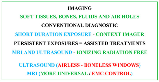
Figure 1.
Summarizing diagram of imaging strategy options accounting for patient comfort and safety.
2.1. MRI Constituents
The shaped MRI image is produced using signals resulting from the interaction of biological tissues with magnetic fields. Three different feature fields are used to create 3D images. The first is a high-intensity static field. It generates a magnetizing vector in living tissue that aligns and measures the density of the protons involved. The second is linked to three low-frequency spatial gradient fields. These locate aligned tissue protons, establishing a 3D restoration of the different spatial divisions of tissue in the images. The third is a radio frequency field. This stimulates the magnetizing vector, allowing its identification with the scanner and the transformation of the effects on the tissues into images [27]. In fact, MRI theoretically aims to image the nuclei of hydrogen atoms, which are held inside living tissues. A hydrogen nucleus that is a proton is a mass of positive charge rotating on itself around an axis. In living tissue, protons are rotated randomly and do not rotate all together. As a result, they display zero subsequent magnetic field and operate out of phase. According to the principle of MRI, protons require three basic arrangements in the examined section of tissue, which align in a fixed direction all the protons, rotate them together and locate their distinct spatial origins. The aligning action could be fulfilled by the introduction of the concerned body tissue section in a high-intensity magnet to steer them simultaneously in the axial direction of its static field B0. To reach their joint spinning, a resonance action can be applied. Thus, one can use an excitation with a radiofrequency (RF) field, B1, having a frequency identical to that of proton rotation natural frequency fL (Larmor frequency of protons). Localizing protons’ distinct spatial positions can be achieved through the use of their related field distinctive values. Thus, a 3D space gradient, G(x, y, z), with pulsations of low-frequency repetitions can be joined to the field B0, permitting the detection of the distinct position values of B0d (x, y, z) = B0 + G(x, y, z). The last conferred fields B0, B1 and G(x, y, z) reflect different natures. It is worth noting that the value of protons’ Larmor frequency fL is a function of the B0 field value and equivalent to 42.5 MHz per tesla and hence the conforming position distinctive frequencies fLd (x, y, z) are functions of B0d (x, y, z). These three fields allow establishing images as follows. The protons are subjected to excitation–relaxation sequences by an RF energy wave, leading to energy supply restoration actions. A suitable tuned RF antenna permits the detection of the restored energy corresponding signals. These are related to the B1 values with frequencies of fLd (x, y, z). Thus, coding of spatial imaging in the concerned tissues can be obtained. Note that B1 frequency is fL that is usually tuned to a value in the center of the explored tissue of fLd (x, y, z).2.2. Features of MRI Fields B
0
, G(x, y, z) and B
1
Respectively the strong magnet, gradient coils and RF coil produce these fields. In the standard procedure of MRI, its proper action necessitates the shield of the magnet and gradient coils and the compensation of their fields. Indeed, a virtuous MRI requests a uniform constant B0 (by using shimming coils) and linear uniform regulated field gradients. These fields necessitate corrections and compensations for reliable performing of the scanner. The RF coil field seems the most exposed, and characterizes a fragility to noise fields and to near introduced external materials. The most widespread form of an RF coil is birdcage-like and is used as an exciting RF source as well as a tuned RF antenna. Figure 2 illustrates a representation of the three MRI components and their conforming fields.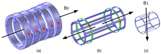
Figure 2.
MRI components and corresponding fields: (
a
) electromagnet B
0
, (
b
) gradient coils (one axis couple), (
c
) RF coil B
1
.
2.3. MRI Compatibility
As mentioned earlier, MRI is sensitive to EMF noise resulting from external field exposure or insertion of specific external matters (magnetic and conductor) within or close to the MRI scaffold. Conventionally, an MRI is shielded regarding external field exposure. We can largely typify an external object as MRI-compatible if it behaves in an MRI-safe manner, not affecting image quality, and working as expected. In addition, the static field magnet and the gradient coils are shielded and their fields are compensated for a reasonable size of inserted matters. As stated in the last section, only the RF coil and its field seem vulnerable for such insertion and it is necessary to control the compliance of the inserted matters with the correct functioning of the scanner. Thus, the inserted external materials should be MRI-compatible, i.e., not perturbing the RF field and image. Only non-magnetic and non-conductor matter can theoretically behave in an MRI-compatible manner. In general, magnetic materials are reduced to trivial-almost-zero sizes. Conducting materials have an indirect perturbing effect on the RF field. They exhibit eddy currents induced by the RF field that perturb the distribution of this field, which alters the image. Such induced currents are directly related to the conductor surface perpendicular to the RF field direction and hence can be reduced by minimizing such surface. Typically, a conducting sheet of negligible thickness positioned parallel to the field direction will almost not cause any field perturbation independent of its surface size. This phenomenon permits the use within the scaffold of conducting matters with specific shapes and orientations.2.4. Image Artifacts
The image quality can be deteriorated for diverse reasons. The scanner itself can be the source of decreased image quality, as in the case of an inefficiently shimmed imager. Living tissues can also diminish the image quality due to susceptibility discrepancies, such as those between soft tissues and air holes in the brain. Moreover, embedded matters within the body such as prostheses and particularly metallic ones can also weaken image quality [34][35][36][37][38][39][40][34,35,36,37,38,39,40]. The image modification due to metallic materials, which present susceptibility variations, depends on the size, the shape and the direction with respect to B1 [27][29][33][27,29,33]. Additionally, an important cause of image artifacts could be the tools, particularly metallic ones, involved in under-imaging processing. Indeed, currents induced in metals not only mainly by the RF fields but also by low-frequency gradient fields can affect the image. These currents could interact mainly with the RF field, which is the most at risk among the fields of an MRI.3. MRI-Assisted Robotic Treatments
As mentioned previously, in surgical or implanted treatments requiring movement or localization control with increased precision, we can use imaging-assisted robotic interventions allowing precise minimally invasive actions. Also, in such image-assisted treatments, non-ionizing MRI seems to be the most adequate, on the condition of controlled external EMF noise. Such noise can come from robotic accessories and medical tools [23][24][25][26][27][28][29][23,24,25,26,27,28,29].3.1. Robotic External Matter Introductions
As mentioned in the last section, only non-magnetic and non-conducting materials can be used in MRI-guided robotic interventions. The robot’s mainframe and therapeutic tools are normally made of non-magnetic and non-conducting materials. However, a robot needs actionable movements. Most competent actuators are the electromagnetic ones using magnetic and conductive materials. Few types of non-electromagnetic actuators with performance suitable for MRI-assisted robotic operation can be used. This could be the case for piezoelectric actuators subject to their MRI compatibility; see, e.g., [41][42][43][44][45][46][47][48][49][50][51][52][53][54][55][56][41,42,43,44,45,46,47,48,49,50,51,52,53,54,55,56]. Such actuators are made of dielectric piezoelectric materials coated with trivial electrodes. The shape and orientation of these electrodes (conductors) relative to the RF field B1 allow possible MRI compatibility. Different keys are proposed for the mechatronic division of the robot containing electronics, sensors, actuators, etc., which address a difficult compatibility question [27][29][41][42][43][44][45][46][57][58][59][60][61][27,29,41,42,43,44,45,46,57,58,59,60,61].3.2. MRI-Compatible Materials
Materials governed by EMF behavior can be magnetic or non-magnetic and a conductor. The non-magnetic materials can behave between dielectric and electric conducting function of EMF wave frequency. Magnetic, dielectric or conductor materials are characterized, respectively, by the permeability μ (or the susceptibility χ), by the permittivity ε or by the conductivity σ. In highly magnetic material, μr >> 1 and μr ≈ χ; note that μ = μ0 · μr and χ = μr − 1. For non-magnetic material, μr = 1 and χ = 0. The relative values of σ and ω · ε (ω = 2 π f) characterize dielectric vs. electrically conducting behaviors of non-magnetic materials. For low f, σ >> ω · ε ≈ σ and for high f, ω · ε >> σ ≈ ω · ε and σ ≈ 0. The materials’ compatibility in MRI is of two types, magnetic and electric, characterized, respectively, by μ (or χ) and σ. A fully MRI-compatible material has zero values for both χ and σ. The dielectric nature of matters does not affect the compatibility. Regarding the RF field distribution, the eventual introduced matters should have μr = 1 and χ = 0, with high ω · ε (will be naturally high in RF range), or conductors with a trivial cross section (e.g., very thin sheet) perpendicular to the RF field B1. With such features, the RF field distribution would not be altered. Note that the induced eddy currents (responsible for field perturbation) in the configured conductor by the current in the RF coil would be extremely negligible due to the trivial conductor section.3.3. Conformity Control of MRI Compatibility
The MRI-compatibility control can be accomplished for existing image-guided MRI systems by using experimental means. This can be carried out by measuring the perturbations of the field resulting in the insertion of checked objects within or near the scaffold according to the case. This is generally accomplished via sensors positioned in specific points in the system. Such techniques in the case of MRI are relatively complex due to the necessity of special shielded expensive chambers and the self-perturbation effects of the measuring sensors. Additionally, the characteristics of a tested object could prove dangerous, leading to degradation of imager components. Furthermore, such a compatibility check is only possible for existing systems and cannot be used for the design of unbuilt systems. In these circumstances, a more advantageous solution could be a compatibility check with numerical modeling techniques via an EMC analysis for the different inserted objects [25][27][29][33][25,27,29,33]. In fact, disturbances in the distribution of EMFs in a given structure caused by the introduction of an external material are related to the EMFs produced in that material. In this case, if the EMF noise is reduced or removed, the field distribution of the target structure will be minorly or not affected.4. Embedded, Wearable and Detachable Devices
Recent advances in the field of biocompatible and biodegradable materials [62][63][64][65][66][67][68][69][70][71][72][73][62,63,64,65,66,67,68,69,70,71,72,73] have enabled the development of implantable static passive tools enabling diagnoses and prediction via mini-sensors, thereby dramatically improving the value and efficiency of patient healthcare [74][75][76][77][78][74,75,76,77,78]. Other static but active implanted devices are proposed to stimulate or trigger an organ, as pumps, neuro-stimulators or pacemakers [79][80][81][82][83][79,80,81,82,83]. In addition, wearable devices, which behave as non-invasive tools in real-time, are available, allowing continuous monitoring of people under treatment and thus providing sufficient medical data to establish the general health status and, furthermore, a preliminary identification of the medical diagnosis [14][15][16][30][31][32][14,15,16,30,31,32]. Additionally, detachable and connectable smart sensing devices, which are also real-time health monitoring systems, exist for functional indications intimately associated with physical conditions. These indications concern the frequency of cardiac functioning, blood circulation pressure, respiratory rate, etc. Such individualized healthcare supervision provides appropriate medical information [84][85][86][84,85,86]. Figure 3 illustrates a summarized representation of the different onboard devices and their functions.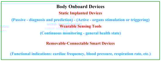
Figure 3.
Summarizing diagram of the different onboard devices and their functions.