1. Introduction
According to International Energy Agency (IEA) report of 2022, global energy-related CO
2 emissions has increased by 0.9% resulting in a new peak of over 36.8 Gt (Gigatonne). The highest contribution of this rise in CO
2 emissions is from the electricity and heat generation sector, where the emissions increased by 1.8% equivalent to 261 million metric tons reaching a peak of 14.6 Gt
[1]. These statistics indicate the need for a reduction in CO
2 emissions and for the utilisation of sustainable energy sources. One of the promising and sustainable energy sources to reduce greenhouse gas emissions and attain a low-carbon economy is geothermal energy. According to the International Renewable Energy Agency (IRENA), geothermal energy delivered around 15.96 gigawatts electricity (GWe) in 2021, with this figure anticipated to rise to 18.3 GWe by 2025, showing a rise from 69,856 GWh (Gigawatt hours) in 2011 to 94,949 GWh in 2020
[2]. When compared to standard heating and cooling systems, the usage of geothermal heating and cooling systems in buildings can result in up to an 85% reduction in carbon emissions. Additionally, geothermal energy has huge potential, with estimates indicating that it may fulfil up to 18% of world electricity demand and satisfy the electricity requirements of approximately 17% of the global population
[2]. It is anticipated that geothermal as renewable energy will progressively play larger roles in the energy sector.
Geothermal energy stands out for its cost-effectiveness and continuous high operational capacity year-round, setting it apart from other renewable energy sources like solar and wind, which are intermittent in nature. Geothermal energy contributes significantly towards the electricity requirements in countries such as Iceland, El Salvador, New Zealand, Kenya, and the Philippines
[3]. In Iceland, over 90% of the heating demand is satisfied by geothermal sources, with around 1000 geothermal sites
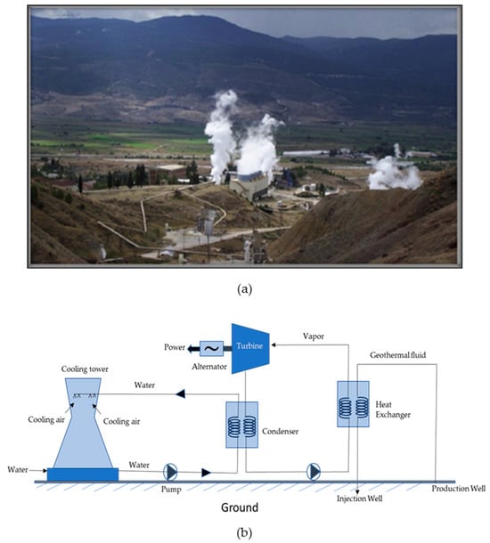
[2][4][2,4]. Figure 1 shows geothermal power plants in Büyük Menderes Graben (BMG) in Western Anatolia and the working of the Organic Rankine Cycle (ORC) binary geothermal plant. Nonetheless, its utilization remains limited in comparison to other sources due to the substantial investment costs associated with surface and subsurface infrastructure and high risk in the first phase, location constraints, requirements of the advanced technology, and the expensive maintenance [3,5,6,7,8]. One of the vital components for the efficient utilization of geothermal energy are heat exchangers which facilitate the transfer of thermal energy from the geothermal fluid to a secondary fluid or the working fluid
[5][6][9,10]. The operational conditions and the complex composition of geothermal water present an array of challenges in the heat exchangers namely extreme temperatures, corrosive fluid, scaling, and abrasive particles. These challenges not only affect the efficiency of heat transfer but also impact the longevity and maintenance requirements of geothermal heat exchangers. In recent years, the exploration of advanced coatings has emerged as a promising method to mitigate the adverse effects of geothermal environment on heat exchangers.
Types of Heat Exchangers
Figure 1. (a) Kızıldere-I single flash-type geothermal powerplant in the BMG and (b) schematic demonstrating working of ORC binary geothermal powerplant.
Types of Heat Exchangers
Heat exchangers (HEXs) find applications for temperature-sensitive mediums, renewable energy technologies, and energy recovery systems
[7][14]. The primary components of HEXs include the fluid streams, their inlet and outlet points, and the heat transfer surface. Depending on the specific type of HEX, additional components like baffles, fins, pipes, and tanks may also be incorporated
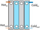
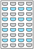
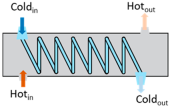
[8][15]. There are various types of HEXs, namely, plate type, shell and tube type, regenerative type, finned tube type, coiled tube type, double-pipe type, printed circuit, scraped surface type HEX, etc.
[9][16]. Thermophysical properties of the fluids involved, difference in streams’ temperature, the materials used and the design of the HEX comprise the key factors that influence heat transfer rates and HEX performance
[7][14].
Heat exchangers can be classified based on the stream phase and arrangement, degree of surface compactness, thermal energy transfer mechanism, and construction
[7][14]. The choice of an appropriate type of heat exchanger (HEX) involves the consideration of multiple factors owing to the diversity of available types, their thermal configurations, material choices, initial investment costs, and ongoing operational expenses. When addressing a particular process requirement, the following factors must be taken into account: operating pressure, operating temperature, fluid characteristics, flow rates, construction materials, fabrication expenses and maintenance expenditures, and susceptibility to fouling, wear, and corrosion
[7][14]. Various types of heat exchangers and their advantages and limitations are mentioned in
Table 1.
Table 1. Advantages and disadvantages of different types of heat exchangers
[7][8][9][10][11][14,15,16,17,18].
2. Challenges and Effective Solutions
2.1. Challenges
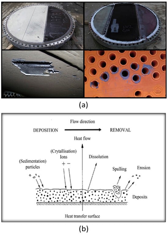
Geothermal environment presents a unique set of challenges, including corrosive nature of geothermal fluids, extreme temperature variations, scaling, and fouling, affecting the efficiency and lifetime of geothermal systems. Figure 2a shows fouling and pitting corrosion observed in the heat exchanger of Büyük Menderes Graben in a geothermal heat exchanger.
Fouling refers to the unwanted build-up of materials onto the surfaces involved in heat transfer
[12][13][19,20]. This accumulation, in the form of salts or other deposits, negatively impacts the performance of operational equipment. The process of fouling is affected by a range of factors such as operational conditions, feed composition, heat exchanger geometry, and surface properties. The
mechanism of fouling is shown in Figure 2b [21]. The different types of fouling that can occur on the surface of heat exchangers include particulate fouling (accumulation of solid particles on the surface, commonly known as silting), biological fouling (involves the growth or deposition of organisms like bacteria and algae), chemical reaction fouling (involves the formation of solid or viscous layers due to reactions between the fluid and heat transfer surface, such as polymerization), and freezing or solidification fouling (occurs due to the solidification of fluid passing through the heat exchanger at low temperatures). Another form of fouling comprises corrosion fouling, which arises due to the chemical reactions or transportation of corrosion products from other system components and their deposition on heat exchanger surface.
Additionally, the most prevalent form of fouling seen in heat exchanger is the crystallization fouling/precipitation fouling caused by deposits like sulphates (SO
42−), carbonates (CO
32−) and silicate (SiO
44−) of calcium. CO
32− and SO
42−, due to their retrograde solubility with respect to temperature, are dominant in low-to-medium-enthalpy geothermal fluids, whereas SiO
44− is dominant in high-enthalpy geothermal fluids. In the case of heat exchangers, amorphous silica (SiO
2) and aluminosilicate are the common deposits, and in some cases, stibnite (Sb
2S
3) scales have also been reported. These deposits hinder heat transfer due to their low conductivity (0.2–3.0 Wm
−1K
−1) and decrease the effective cross-sectional area within the heat exchanger tube, leading to the reduced efficiency raising concerns due to decreased flow rate and increased pressure drop
[14][22]. Consequently, this results in increased energy consumption and maintenance costs.
The
Figure 2. process(a) of deposition of calcium/magnesium from the fluid is often referred to as scaling. S
ilica scaling, observed in heat exchangers, arises due to the high concentration of silica in the brine solution of geothermal reservoirs. Two major factors governing the rate of silica deposition are the temperature and the pH of brine. Scale deposition increases with an increase in the pH and a decrease in the temperature, mostly occurring in the cooler parts of the plant. However, antimony and arsenic precipitates are mostly seecaling and pitting corrosion observed in heat exchanger of Büyük Menderes Graben in geothermal
brines at high temperaturesheat [15]. A study conducte
d on the small tubular heat exchanger
s of Soultz-sous-forêts by Ledésert, B. A. et al. mentioned the occurrence of PbS and (
lead sulphideb)
scaling alongside As and Sb sulphides and halite [16]. One of the im
pacts of silica scaling include
s the roughening of the heat exchanger surface. In the Wairakei geothermal power station, the roughness generated due to silica scales in a shell and tube heat exchanger resulted in a drop in pressure and flow rate, eventually leading to a decrease in the efficiency of the heat exchanger of the ORC [12]chanism of fouling.
The process of deposition of calcium/magnesium from the fluid is often referred to as scaling. Silica scaling, observed in heat exchangers, arises due to the high concentration of silica in the brine solution of geothermal reservoirs. Two major factors governing the rate of silica deposition are the temperature and the pH of brine. Scale deposition increases with an increase in the pH and a decrease in the temperature, mostly occurring in the cooler parts of the plant. However, antimony and arsenic precipitates are mostly seen in geothermal brines at high temperatures [11]. A study conducted on the small tubular heat exchangers of Soultz-sous-forêts by Ledésert, B. A. et al. mentioned the occurrence of PbS (lead sulphide) scaling alongside As and Sb sulphides and halite [24]. One of the impacts of silica scaling includes the roughening of the heat exchanger surface. In the Wairakei geothermal power station, the roughness generated due to silica scales in a shell and tube heat exchanger resulted in a drop in pressure and flow rate, eventually leading to a decrease in the efficiency of the heat exchanger of the ORC [19].
Corrosion is another significant challenge that disrupts the proper functioning of geothermal power plants. Factors such as pH, dissolved oxygen levels, temperature, and the presence of corrosive compounds like chlorides, hydrogen sulphides, and carbon dioxide in the brine play an important role in influencing the corrosion process, consequently leading to the failure of components. Various methods are employed to assess the corrosion resistance of coatings, such as autoclave tests, visual examination, and the most common method includes electrochemical assessments. Electrochemical evaluations include open-circuit potential determination, potentiostatic and potentiodynamic (derived Tafel plots are used to determine the corrosion rates), and linear polarisation resistance. The nature of corrosion varies depending on the fluid chemistry of power plants
[17][8] and the differences in the geographical region. The presence of peeling and spalling in coating materials is commonly considered as an indication of corrosion. In a geothermal environment, depending on the materials and components, different types of corrosion are observed, namely uniform corrosion (occurs evenly across a materials surface, typically via the interaction of geothermal fluids with metal surfaces over a long time period), microbial corrosion (occurs as a result of activities of micro-organisms such as bacteria, algae, fungi, etc.), pitting corrosion (observed when there is a breach in the passive layer resulting in the exposure of metal to corrosive surroundings), galvanic corrosion (occurs when two different metals come in contact in an electrolyte and create a galvanic cell), and crevice corrosion (a localized and aggressive form of corrosion that is typically initiated by the trapping of moisture, salts, or other corrosive agents in these tight spaces) are observed. Some other corrosion-related failures include hydrogen embrittlement and stress-induced corrosion. Hydrogen embrittlement occurs due to the diffusion of hydrogen atom into a metal microstructure on exposure of the metal to a hydrogen-containing atmosphere. This makes the material susceptible to cracking by reducing its ductility and eventually results in the failure of the component. If this phenomenon occurs in an environment having a high content of H
2S (hydrogen sulphide) and is followed by failure of the material owing to stress, it is known as sulphide stress cracking
[18][19][25,26]. Morake, J B et al. identified hydrogen-induced cracking and sulphide-induced stress corrosion cracking as the cause behind the failure of CuNi10Fe (cupronickel) tubes in a shell-and-tube heat exchanger. The exchanger tubes operated for five months within a temperature range of 144 °C to 27 °C and at a pressure of 2.0 bar. Erosion was observed in the cupronickel layer and it was facilitated by high pressure, which allowed hydrogen entry into the tubes. Additionally, the H
2S environment contributed to hydrogen ingress, leading to sulphide stress corrosion cracking in these tubes
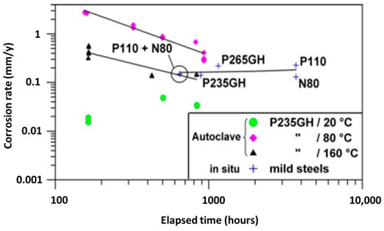
[20][27]. Mundhenk, M. et al. performed in situ and laboratory-based corrosion tests on various mild steels (API N80, API P110, P235GH, and P265GH), stainless steels (430 F, 316 L), alloy 904 L, duplex alloy 318 L, super-duplex alloy 31, nickel-base alloys 59, 625, and titanium grade 2. All metals were analysed in a Soultz geothermal brine environment in order to obtain a better understanding of corrosion and scaling in the Soultz-sous-Forêts geothermal power plant, France. The corrosion tests were performed through autoclave testing using the weight loss method at three temperatures: 20 °C, 80 °C, and 160 °C. In their findings, the authors observed that mild steel displayed uniform corrosion and localised corrosion, specifically, pitting and filiform corrosion.
Moreover, it exhibited long-term uniform corrosion rates, lower than 0.2 mm/year at a temperature of 20 °C
, and the highest corrosion
was rate was observed at a temperature of 80 °C (Figure 3). Corrosion was coupled with the formation of a dense and adherent scale that led to the protection of substrate. Pitting corrosion is observed in stainless steels 430 F and 316 L, and the authors rendered them as an unsuitable candidate for utilization in Upper Rhine valley geothermal environments. Higher-alloyed materials demonstrated a high resistance against uniform corrosion and portrayed corrosion rates of <0.005 mm/year, and the authors identified these to be suitable for geothermal service
[21][28].
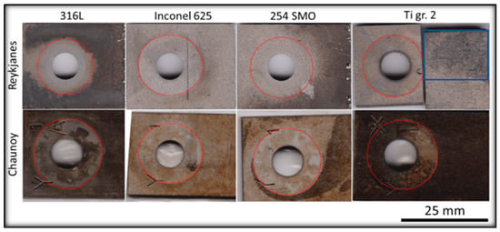
In the ORC binary plant, corrosion is observed in different heat exchanger components such as tubes and channels due to their contact with the aggressive geothermal fluid. Thus, materials like stainless steel, titanium, and duplex steels are preferred over the carbon steel for construction of such components [8,29]. Faes, W. et al. have given a detailed discussion on the failure of heat exchangers due to corrosion [29]. The practice of subjecting materials to the actual conditions of geothermal environment provides a means to evaluate the response of the materials towards the extreme conditions of the geothermal fluids and to predict the longevity and suitability of these materials. Their results revealed subsurface cracks and Cu deposits on Ti grade 2 in Reykjanes, whereas in Chaunoy, the corrosion products were rich in Fe and S. Erosion was also observed in the Ti grade 2 used in both sites. The 254 SMO exposed in both sites showed subsurface cracks, and in Reykjanes, pitting corrosion was also observed. Two corrosion layers were formed on the 316L exposed surface in Reykjanes, and local corrosion was observed in Chaunoy. The differences observed are mainly due to pH differences in both the plants. The corrosion products were of Fe, O, and Cr and a trace of Al in Chaunoy. The Inconel 625 showed no evidence of corrosion on the surface exposed in Reykjanes but showed subsurface cracks after exposure [30].
Figure 3. Corrosion rate of mild steel from autoclave measurements at different temperatures.
In the ORC binary plant, corrosion is observed in different heat exchanger components such as tubes and channels due to their contact with the aggressive geothermal fluid. Thus, materials like stainless steel, titanium, and duplex steels are preferred over the carbon steel for construction of such components [8,29]. Faes, W. et al. have given a detailed discussion on the failure of heat exchangers due to corrosion [29]. The practice of subjecting materials to the actual conditions of geothermal environment provides a means to evaluate the response of the materials towards the extreme conditions of the geothermal fluids and to predict the longevity and suitability of these materials. Various studies have relied on this; for instance, Davíðsdóttir, S. et al. investigated the local corrosion of four different heat exchanger materials (316L, 254 SMO, Inconel 625, Titanium grade 2) in two different high saline geothermal plants: Reykjanes, Iceland: 200 °C and 18 bar vapour; Chaunoy, France: 94 °C and 9.5 bar fluid (Figure 4) [30]. Their results revealed subsurface cracks and Cu deposits on Ti grade 2 in Reykjanes, whereas in Chaunoy, the corrosion products were rich in Fe and S. Erosion was also observed in the Ti grade 2 used in both sites. The 254 SMO exposed in both sites showed subsurface cracks, and in Reykjanes, pitting corrosion was also observed. Two corrosion layers were formed on the 316L exposed surface in Reykjanes, and local corrosion was observed in Chaunoy. The differences observed are mainly due to pH differences in both the plants. The corrosion products were of Fe, O, and Cr and a trace of Al in Chaunoy. The Inconel 625 showed no evidence of corrosion on the surface exposed in Reykjanes but showed subsurface cracks after exposure [30].
Figure 14. Corroshowsion of different forms of corrosion and scaling and the factors that can accelerate these phenomena. Moreover, it includes a brief mention of some of the effective solutionsheat exchanger materials exposed to pressure vessel at Reykjanes and flow line pipe at Chaunoy, where red circles mark the area masked partially from geothermal environment and the blue box indicates the exposed area of Ti gr.2.
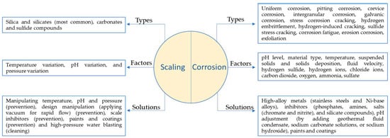
Figure 5 shows different forms of corrosion and scaling and the factors that can accelerate these phenomena. Moreover, it includes a brief mention of some of the effective solutions.
Figure 15. Different forms of corrosion and scaling in geothermal environment.
2.2. Effective Solutions
The issues outlined above limit the effectiveness of the heat exchanger, raise capital, operating, and maintenance expenses, and also give rise to safety concerns. As a result, ensuring optimal heat exchanger performance has prompted extensive research into developing effective strategies for tackling fouling and corrosion. Research has shown that the design phase of the heat exchangers plays a crucial role in mitigating fouling
[22][31]. This involves considering factors such as shape, geometry, operating conditions, and ease of cleaning. Various studies have utilized chemical and mechanical techniques to mitigate the corrosion and fouling of components in geothermal environment. Chemical inhibitors, both organic and inorganic, with poly functionality such as phosphates, phosphonates, and carboxylates, are widely used in heat exchangers of complex geometries for mitigating fouling
[23][24][25][32,33,34]. Scheiber, J. et al.
[26][35] studied the scaling inhibition in Soultz-sous-Forêts by a phosphonate-based inhibitor against Sr and Ba deposits. However, these inhibitors negatively impact the environment, and their stability is temperature-dependent
[15][11]. Furthermore, the applications of these inhibitors developed for ionic solids becomes challenging when dealing with covalent compounds like silica, which affects the efficiency and selectivity of them
[27][36]. Cho, Y. and B. G. Choi have used the electronic anti-fouling (EAF) technique in order to mitigate fouling in heat exchangers
[28][37]. Mechanical techniques, such as laser machining and electrical discharge machining (EDM), are employed for creating anti-fouling surfaces, but they tend to be relatively costly and less efficient. Both EDM and magnetron sputtering have been applied to create C-films on Cu substrates, resulting in elevated water contact angles
[29][38]. A simple and relatively cheap method of fabricating superhydrophobic surface using CaCO
3 self-assembled coatings modified by sodium stearate in simulated geothermal water has been investigated by Wang, G. G. et al. These coatings were found to have a contact angle of 158.9 °C after 48 h of immersion in geothermal water
[30][39]. There is research that has explored the substitution of CO
2 for acid additions and found it to be effective in regulating pH and managing scale inhibition
[27][36].
Even though Ti alloys and stainless steels are used in various components of geothermal plants, due to the passive layer providing resistance to corrosion and scaling. The interaction of silicate, silica, and calcite present in the solution with the surface oxide layer of these materials results in the increased adhesion of these compounds, thus reducing the efficiency of the geothermal component. These also react with the chloride ions, causing corrosion of the components
[31][40]. In addition, compared to carbon steel, these are expensive; for instance, stainless steel AISI 316 costs EUR 3480, and AISI 306 costs EUR 2900 per tonne, whereas carbon steel has a cost of EUR 900 per tonne
[32][41]. Hence, it could be more cost-effective to apply a compatible protective coating to carbon steel, rendering it suitable for use in geothermal heat exchangers, rather than opting for more expensive stainless steels. The selection of a coating and its performance for any substrate depends on the coating materials and its microstructure.
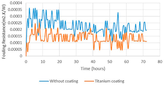
And of all the employed methods, surface modification through coatings emerges as an exceptionally efficient and economically viable approach to address challenges within geothermal heat exchangers; for example, Figure 6 provides a clear illustration of the impact of coatings on fouling rates, highlighting the significance of coatings.
Figure 6. I
n recent tim
es, high-entropy alloys have gained significant attention for applications in geothermal environments. A study led by Thorhallsson, A. I. et al. at the Hellisheidi geothermal site explored the use of CoCrFeNiMo(0.85) and Al(0.5)CoCrFeNi high-entropy alloy coatings through laser melt deposition on the C-steel [S3257R] anage demonstrating formation of calcium carbonate deposits on an uncoated stainless steel
[316L]. Notably, the former alloy exhibited superior erosion–corrosion resistance compared to the latter in the geothermal environment [33]. Geambazu, L. E. et al. found that the electro(SS 316L) and titanium-
spark deposited CoCrFeNiMo(0.85) performed well in a geothermal environment, and the rate of co
rrosion of the coated 316L ated stainless steel su
bstrate in 3.5 wt% NaCl was 0.00016 mm/year [34]. Oppong Boakye, G. et al. rfac
onducte
d examinations into CoCrFeNiMox (x = 20% and 27%)-coated sur f
aces, emplo
ying laser cladding, high-velocity oxy-fuel (HVOF), and electro-spark deposition techniques, for potential application in geothermal environments [35]r heat exchangers.
In recent times, high-entropy alloys have gained significant attention for applications in geothermal environments. A study led by Thorhallsson, A. I. et al. at the Hellisheidi geothermal site explored the use of CoCrFeNiMo(0.85) and Al(0.5)CoCrFeNi high-entropy alloy coatings through laser melt deposition on the C-steel [S3257R] and stainless steel [316L]. Notably, the former alloy exhibited superior erosion–corrosion resistance compared to the latter in the geothermal environment [42]. Geambazu, L. E. et al. found that the electro-spark deposited CoCrFeNiMo(0.85) performed well in a geothermal environment, and the rate of corrosion of the coated 316L stainless steel substrate in 3.5 wt% NaCl was 0.00016 mm/year [43]. Oppong Boakye, G. et al. conducted examinations into CoCrFeNiMox (x = 20% and 27%)-coated surfaces, employing laser cladding, high-velocity oxy-fuel (HVOF), and electro-spark deposition techniques, for potential application in geothermal environments [44].
