Your browser does not fully support modern features. Please upgrade for a smoother experience.
Please note this is a comparison between Version 1 by Azamat Yeshmukhametov and Version 2 by Camila Xu.
Tensegrity robots offer several advantageous features, such as being hyper-redundant, lightweight, shock-resistant, and incorporating wire-driven structures. Despite these benefits, tensegrity structures are also recognized for their complexity, which presents a challenge when addressing the kinematics and dynamics of tensegrity robots.
- prismatic tensegrity
- robot kinematics and kinetics
- tensegrity structure
1. Introduction
A tensegrity structure (see Figure 1) can be defined as a truss-like system that includes elements able to transmit loads in a single direction in space: these are struts/bars (compression members) and wires/cables (tension members). The connections between elements are constituted by ball joints, which also represent the only points at which external loads can be applied. As a consequence, all elements of a tensegrity structure can be loaded only axially, which on the one hand simplifies their modeling, and on the other hand allows one to choose element geometry and materials specialized for axial loads [1], enabling “the creation of structures with high rigidity per unit mass” [2]. Due to its structure, a tensegrity can easily absorb external forces and shocks [3]: for example, NASA proposed a mobile robot based on a ball-shaped tensegrity structure with shock-absorbing features [4]. The first research work on tensegrity systems focused on the study of structure equilibrium and stability analysis [5]. The calculation of the initial equilibrium state of a tensegrity structure, which is in itself a nontrivial task, is termed as “form-finding” [6][7][8][6,7,8]. Recently, researchers have introduced a numerical approach for determining the stability of general structures when their structural stiffness matrix K is positive semi-definite. This stability is defined as the structure’s ability to return to its original state after the application of a small external load [9][10][9,10].
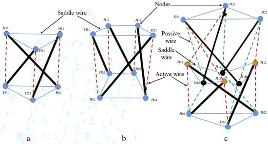
Figure 1. Prismatic tensegrity robot structures: (a) single segment triangular prismatic structure, (b) single segment quadrangular prismatic tensegrity, and (c) dual segment triangular prismatic structure with two layers.
2. Tensegrity Kinematics and Kinetics
Tensegrity kinematics is a challenging problem, as it is more complex than serial robot kinematics. Indeed, a tensegrity robot is made of a network of strings and bars with complex wire routing, and inherently has a parallel and closed linkage architecture resulting in complex forward kinematics [11] with structural constraints [12]. One of the most popular methods of solving forward kinematics, consisting of an iterative approach, is the Newton–Raphson method [13]. Alternative methods have been proposed based on genetic algorithms [14][15][14,15], potential energy [16][17][16,17], and deformation kinematics [18]. Another proposed kinematics formulation for a tensegrity robot structure is the deformation kinematics method. This method imposes nodes in Euclidean space that are described by the nodal coordinates with respect to an inertial Cartesian coordinate system. Position of the joints is defined by deformed or stretched truss elements with respect to the initial position [18]. This is a nontrivial task, as the form of the tensegrity structure should be symmetric in terms of wire tensions. Finding the initial form of the robot after moving is also a crucial task. There are some mechanical factors that deeply affect form-finding, such as friction. The whole mechanism is driven by wires and has some contact between wires and robot rigid components, which yields friction, causing a negative effect on the robot motion, and requires more motor torque than it should [19][20][21][22][23][24][19,20,21,22,23,24].
A problem related to kinematics is that of determining the kinetics of a tensegrity structure. Methods that account for the deformability of bars were described in [18][25][26][18,25,26]. A method based on a mixed Lagrangian–Eulerian approach was presented in [18] to derive the linearized equation of motion around equilibrium configurations for modal analysis and numerical simulation. Another approach to obtain linearized equations of motion was introduced in [25] utilizing second-order ordinary differential equations, which simplified the problem as compared to using partial differential equations, as in [18]. The major drawback of the method in [25] is the large number of parameters required for calculations, related to Young’s modulus and geometrical properties. Finally, the method in [26] directly handles nonlinear tensegrity dynamics.
The most significant and well-known studies on tensegrity are those of Skelton and co-workers. In their formulation, the bars in the tensegrity are considered as rigid bodies, and the nonlinear dynamics of the structure are represented using node, bar, and string connectivity matrices [27]. For example, the node matrix includes the coordinates in the Cartesian space of all nodes (i.e., endpoints of bars) of the structure: it has three rows and a number of columns equal to twice the number of bars. A dynamical model that employs such a formulation has a number of states equal to 12 times the number of bars (i.e., position and velocity coordinates of all bar nodes in the Cartesian space). This is a non-minimal set of coordinates, as the tensegrity dynamics is described using six degrees of freedom for each bar, instead of the minimal number, i.e., five (see, e.g., [18][25][26][18,25,26]). This might seem to be a disadvantage compared to frameworks based on minimal coordinates; however, Skelton’s formalism has some remarkable advantages. First, it avoids using long chains of trigonometric functions, as the only nonlinearities in the dynamic equations are ratios and square roots. Second, the mass matrix of the system, although of larger size, becomes constant, which simplifies certain calculations (mainly, its inversion).
Skelton’s formalism has been used in several studies. For example, a unified formulation of the dynamics of general class-k tensegrity systems—tensegrity is of class-k when it has a maximum of k is rigid bars connected by ball joints—was studied in [28][29][28,29]. In [30], the formulation of [29] was extended to account for the presence of damping forces and forces along connected strings passing through several nodes. A related framework was proposed by Goyal et al. [31] to simulate tensegrity dynamics in the presence of rigid bars and massive strings, allowing one to distribute the mass of the strings into a number of point masses along the string, at the same time preserving the exact dynamics of the rigid bars. Finally, a software toolbox for static analysis and simulation of the dynamics of tensegrity systems based on the modeling framework of [31] was created and is described in [32].
The kinematics of tensegrity structures pose a challenge due to the need for simultaneous motor control, whereas serial manipulators with rigid links only require control of individual motors [33]. The wire-net structure of tensegrity robots makes them susceptible to movements and shocks from any of its actuators, whereas kinematics in serial manipulators are based on their degrees of freedom [34][35][34,35]. Tensegrity structures have a large number of structural constraints, making kinematic formulation based on constraint equations necessary to achieve the desired degrees of freedom, unlike the simpler kinematics formulation in serial manipulators.
3. Prismatic Tensegrity Structures
A recent survey paper [36] classified tensegrity robots into different classes: prismatic [37], spherical [38][39][38,39], humanoid musculoskeletal [40][41][42][40,41,42], and bio-inspired [43]. Prismatic tensegrity robots (see Figure 1) that are based on the composition of so-called tensegrity prisms constitute one of the most popular solutions adopted to date, which facilitates stability, symmetry, and self-equilibrium. A tensegrity prism is composed of p struts and, usually, at least 3𝑝 strings that form p-sided polygons on the top and bottom, such as triangular tensegrity prism with 3 struts and 9 strings, and quadrilateral tensegrity prism with 4 struts and 12 strings’ [36]. Triangular and quadrilateral prisms (i.e., 𝑝=3 and 𝑝=4, respectively) constitute the simplest and most commonly used designs. The fact that prismatic tensegrity structures usually consist of repeating patterns makes it possible to also use a simplified assembly sequence. Prismatic tensegrity structures have been utilized to create tensegrity robots equivalent to industrial robot arms with open-chain kinematic structure [44][45][44,45]. Due to their lightweight components (i.e., bars and strings) and parallel architecture, these robots can manipulate higher payloads, relative to their weight, as compared to traditional industrial manipulators [36]. Tensegrity robots are well-suited for operating in uneven and unstructured environments, as they do not require additional infrastructure and facilities, thus reducing the cost of exploitation [46]. Despite these advantages, tensegrity robots cannot achieve high-speed operation comparable to delta manipulators with a parallel structure [47][48][47,48]. On the other hand, compared to wire-driven robots such as continuum manipulators [49][50][49,50], tensegrity robots have a significantly higher payload capacity.